1995 JEEP YJ blower motor
[x] Cancel search: blower motorPage 2111 of 2158
(5) Remove expansion valve from the evaporator.
INSTALLATION
Add 30 ml (1 fluid oz.) of refrigerant oil to the A/C
system if the evaporator is replaced.
(1) Install expansion valve on evaporator.
(2) Position evaporator in the housing. Install and
tighten the evaporator retaining screws.
(3) Install cycling clutch switch into evaporator. In-
stall the top of the evaporator housing.
(4) Install the evaporator/blower housing.
(5) Evacuate and charge A/C system as outlined in
this section.
EXPANSION VALVE
REVIEW ALL WARNINGS AND CAUTIONS IN
THIS GROUP BEFORE PERFORMING THIS
OPERATION.
REMOVAL
(1) Recover refrigerant from A/C system.
(2) Remove the coolant bottle and bracket.
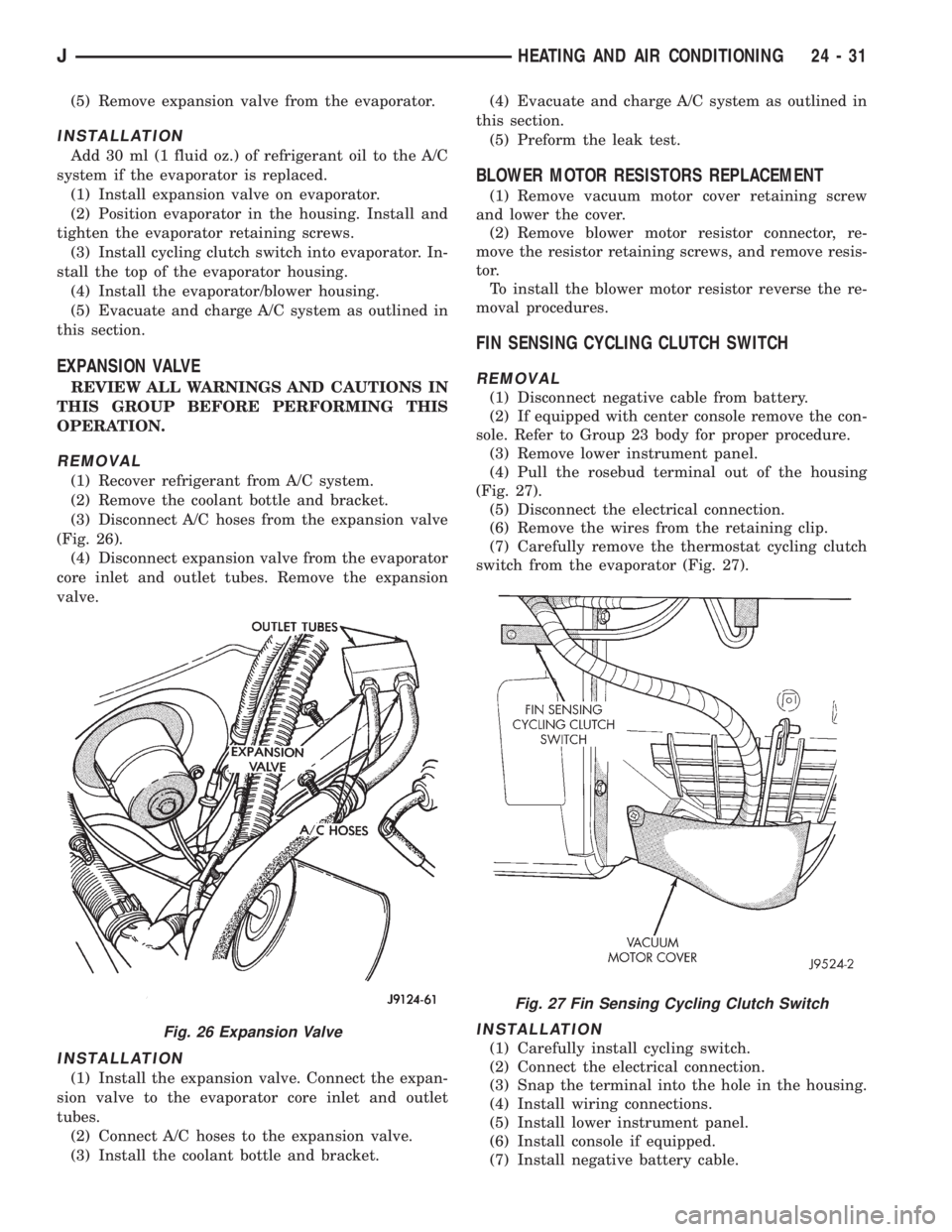
(3) Disconnect A/C hoses from the expansion valve
(Fig. 26).
(4) Disconnect expansion valve from the evaporator
core inlet and outlet tubes. Remove the expansion
valve.
INSTALLATION
(1) Install the expansion valve. Connect the expan-
sion valve to the evaporator core inlet and outlet
tubes.
(2) Connect A/C hoses to the expansion valve.
(3) Install the coolant bottle and bracket.(4) Evacuate and charge A/C system as outlined in
this section.
(5) Preform the leak test.
BLOWER MOTOR RESISTORS REPLACEMENT
(1) Remove vacuum motor cover retaining screw
and lower the cover.
(2) Remove blower motor resistor connector, re-
move the resistor retaining screws, and remove resis-
tor.
To install the blower motor resistor reverse the re-
moval procedures.
FIN SENSING CYCLING CLUTCH SWITCH
REMOVAL
(1) Disconnect negative cable from battery.
(2) If equipped with center console remove the con-
sole. Refer to Group 23 body for proper procedure.
(3) Remove lower instrument panel.
(4) Pull the rosebud terminal out of the housing
(Fig. 27).
(5) Disconnect the electrical connection.
(6) Remove the wires from the retaining clip.
(7) Carefully remove the thermostat cycling clutch
switch from the evaporator (Fig. 27).
INSTALLATION
(1) Carefully install cycling switch.
(2) Connect the electrical connection.
(3) Snap the terminal into the hole in the housing.
(4) Install wiring connections.
(5) Install lower instrument panel.
(6) Install console if equipped.
(7) Install negative battery cable.
Fig. 26 Expansion Valve
Fig. 27 Fin Sensing Cycling Clutch Switch
JHEATING AND AIR CONDITIONING 24 - 31
Page 2112 of 2158
COMPONENT SERVICEÐYJ VEHICLES
INDEX
page page
A/C Blower Motor......................... 35
A/C Condenser........................... 34
Blower Motor (Heating)..................... 33
Blower Motor/Air Door Motor Switch Replacement . 32
Defroster Nozzle and Duct.................. 33
Description.............................. 32
Evaporator and Housing.................... 35
Expansion Valve.......................... 35Fresh Air Door Vacuum Motor................ 34
Fresh Air Intake Duct...................... 34
Heater Control Replacement................. 32
Heater Core and Housing................... 33
Receiver-Drier Replacement................. 35
Temperature Control Thermostat.............. 34
Vent Door Control Cables................... 32
DESCRIPTION
The air conditioning evaporator housing is
mounted to the bottom of instrument panel. The
evaporator, blower motor, thermostat, and expansion
valve are located in the evaporator housing. The com-
pressor, condenser, receiver-dryer and refrigerant
lines are located in the engine compartment.
The heater housing is mounted to the dash panel
behind the instrument panel.
HEATER CONTROL REPLACEMENT
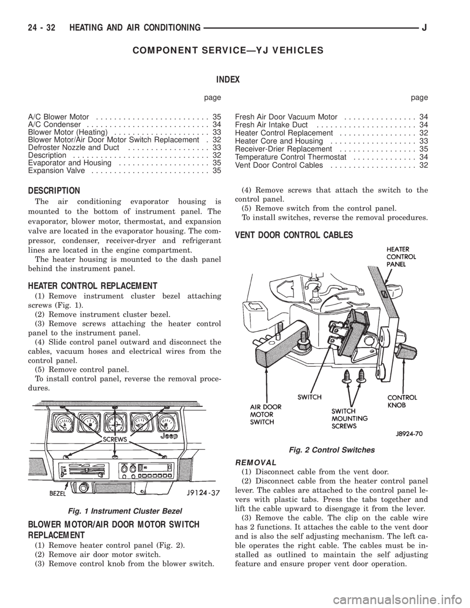
(1) Remove instrument cluster bezel attaching
screws (Fig. 1).
(2) Remove instrument cluster bezel.
(3) Remove screws attaching the heater control
panel to the instrument panel.
(4) Slide control panel outward and disconnect the
cables, vacuum hoses and electrical wires from the
control panel.
(5) Remove control panel.
To install control panel, reverse the removal proce-
dures.
BLOWER MOTOR/AIR DOOR MOTOR SWITCH
REPLACEMENT
(1) Remove heater control panel (Fig. 2).
(2) Remove air door motor switch.
(3) Remove control knob from the blower switch.(4) Remove screws that attach the switch to the
control panel.
(5) Remove switch from the control panel.
To install switches, reverse the removal procedures.
VENT DOOR CONTROL CABLES
REMOVAL
(1) Disconnect cable from the vent door.
(2) Disconnect cable from the heater control panel
lever. The cables are attached to the control panel le-
vers with plastic tabs. Press the tabs together and
lift the cable upward to disengage it from the lever.
(3) Remove the cable. The clip on the cable wire
has 2 functions. It attaches the cable to the vent door
and is also the self adjusting mechanism. The left ca-
ble operates the right cable. The cables must be in-
stalled as outlined to maintain the self adjusting
feature and ensure proper vent door operation.
Fig. 1 Instrument Cluster Bezel
Fig. 2 Control Switches
24 - 32 HEATING AND AIR CONDITIONINGJ
Page 2113 of 2158
INSTALLATION
(1) Install the cables to the heater control panel.
(2) Connect right vent door cable. DO NOT connect
the left door cable at this time.
(3) Open and close the right vent door (one time)
using the air control lever on the heater control
panel.
(4) Connect left vent door cable.
(5) Open and close both vent doors with the air
control lever. Verify that both vent doors open at the
same time.
HEATER CORE AND HOUSING
REVIEW ALL WARNINGS AND CAUTIONS IN
THIS GROUP BEFORE PERFORMING THIS
OPERATION.
REMOVAL
(1) Drain coolant from the radiator.
(2) Disconnect heater hoses.
(3) Disconnect vent door cables.
(4) Disconnect blower motor wire.
(5) Disconnect defroster duct.
(6) Remove nuts that attach the heater housing
studs to the engine compartment side of the dash
panel.
(7) Remove heater housing assembly by tilting it
downward, to disengage it from the defroster duct.
Pull it rearward and out from under the instrument
panel.
(8) Remove heater hosing cover from the housing.
(9) Remove heater core from the housing.
INSTALLATION
(1) Install the heater core into the housing and in-
stall the cover on the housing.
(2) Position heater housing on the dash panel. Be
sure the housing studs all extend through the dash
panel.
(3) Install the seals on the heater core outlet and
inlet tubes and over the blower motor housing.
(4) Install attaching nuts on the housing studs.
CAUTION: DO NOT over tighten the attaching nuts.
The housing could become distorted causing air
leaks and improper heater door operation. Tighten
the nuts alternately and evenly until 2 stud threads
are visible beyond each nut.
(5) Connect defroster duct to the housing.
(6) Connect blower motor wire.
(7) Connect vent door control cables.
(8) Connect heater hoses.
(9) Fill cooling system.
(10) Check system operation.
BLOWER MOTOR (HEATING)
REMOVAL
(1) Remove heater housing.
(2) Remove blower motor-to-heater housing attach-
ing screws/nuts.
(3) Remove blower motor from the housing.
INSTALLATION
(1) Position blower motor into housing.
(2) Install and tighten blower motor-to-heater
housing attaching screws/nuts.
(3) Install heater housing.
(4) Check blower motor and heater operation.
DEFROSTER NOZZLE AND DUCT
REVIEW ALL WARNINGS AND CAUTIONS IN
THIS GROUP BEFORE PERFORMING THIS
OPERATION.
REMOVAL
(1) Drain coolant from the radiator.
(2) Disconnect heater hoses.
(3) Remove nuts attaching the heater housing
studs to the engine compartment side of the dash
panel.
(4) Disconnect speedometer cable.
(5) Remove glove box.
(6) Tilt heater housing back and pull it rearward
and out from under the instrument panel.
(7) Disconnect vent control cables.
(8) Remove fresh air intake grille from the cowl.
(9) Remove fresh air intake duct.
(10) Lower windshield.
(11) Remove defroster nozzle attaching screws and
remove the nozzle and duct.
INSTALLATION
(1) Install defroster nozzle and duct.
(2) Raise and secure the windshield.
(3) Install fresh air intake duct.
(4) Install fresh air intake grille on the cowl.
(5) Install vent cables.
(6) Position heater housing on the dash panel. Be
sure all the housing studs extend through the dash
panel.
(7) Install seals on the blower motor and heater
core inlet and outlet tubes.
(8) Install on the housing studs.
CAUTION: DO NOT over tighten the attaching nuts.
The housing could become distorted causing air
leaks and improper heater door operation. Tighten
the nuts alternately and evenly until 2 stud threads
are visible beyond each nut.
(9) Install glove box.
(10) Connect speedometer cable.
JHEATING AND AIR CONDITIONING 24 - 33
Page 2114 of 2158
(11) Connect the heater hoses.
(12) Fill cooling system.
FRESH AIR DOOR VACUUM MOTOR
REMOVAL
(1) Remove glove box and assist handle.
(2) Disconnect vacuum hose from the motor.
(3) Remove motor lever retaining clip.
(4) Remove motor attaching nuts and remove the
motor from the fresh air duct.
INSTALLATION
(1) Position motor on fresh air duct and install the
motor attaching nuts.
(2) Align motor lever with the air door lever and
install the lever retaining clip.
(3) Connect vacuum hose to the motor.
(4) Install glove box and assist handle.
FRESH AIR INTAKE DUCT
REVIEW WARNINGS AND CAUTIONS IN
THIS GROUP BEFORE PERFORMING THIS
OPERATION.
REMOVAL
(1) Drain coolant from the radiator.
(2) Disconnect heater hoses.
(3) Remove nuts attaching the heater housing
studs to the dash panel from inside the engine com-
partment.
(4) Disconnect speedometer cable.
(5) Remove glove box and assist handle.
(6) Tilt heater housing back and pull it rearward
and out from under the instrument panel.
(7) Disconnect vent cables.
(8) Remove windshield bracket bolts and lower
windshield.
(9) Remove fresh air intake grille from the cowl.
(10) Remove fresh air intake duct.
INSTALLATION
(1) Install fresh air intake duct.
(2) Install defroster nozzle and duct.
(3) Raise and secure the windshield.
(4) Install fresh air grille on the cowl.
(5) Install vent cables.
(6) Position heater housing on the dash panel. Be
sure all the housing studs extend through the dash
panel.
(7) Install seals on the blower motor and heater
core inlet and outlet tubes.
(8) Install nuts on the heater housing studs.
CAUTION: DO NOT over tighten the attaching nuts.
The housing could become distorted causing air
leaks and improper heater door operation. Tightenthe nuts alternately and evenly until 2 stud threads
are visible beyond each nut.
(9) Install glove box and assist handle.
(10) Connect speedometer cable.
(11) Connect heater hoses.
(12) Fill cooling system.
TEMPERATURE CONTROL THERMOSTAT
REMOVAL
(1) Remove mounting bolts and lower the evapora-
tor housing.
(2) Remove the attaching screws holding the top
and bottom housings together.
(3) Separate the housings.
(4) Remove the thermostat.
INSTALLATION
(1) Install temperature control thermostat. Insert
thermostat capillary tube into the evaporator coil a
minimum of 50 mm (2 inch).
CAUTION: Handle the tube with care to avoid bends
or kinks that could cause the thermostat to mal-
function.
(2) Assemble the housing and install the attaching
screws. DO NOT over tighten the attaching screws.
(3) Install the evaporator housing.
A/C CONDENSER
REVIEW WARNINGS AND CAUTIONS IN
THIS GROUP BEFORE PERFORMING THIS
OPERATION.
REMOVAL
(1) Recover refrigerant from A/C system.
(2) Drain the radiator.
(3) Remove fan shroud and radiator.
(4) Disconnect A/C line from the condenser.
(5) Remove condenser attaching screws and tilt the
bottom of the condenser toward the engine.Plug all
the condenser openings to prevent entry of dirt
or moisture.
(6) Working from under the vehicle, disconnect the
receiver-drier to-evaporator hose fitting from the re-
ceiver-drier.
(7) Remove condenser and receiver-drier as an as-
sembly.
(8) Remove receiver-drier from the condenser, if
necessary.
INSTALLATION
Add 30 ml (1 fluid oz.) of refrigerant oil to the A/C
system if the condenser is replaced.
(1) Attach receiver-drier to the condenser.
(2) Install condenser and connect A/C line to the
receiver-drier.
24 - 34 HEATING AND AIR CONDITIONINGJ
Page 2115 of 2158
(3) Install condenser attaching screws.
(4) Connect condenser A/C line.
(5) Install radiator and fan shroud.
(6) Fill coolant system (Refer to cooling for proper
procedure).
(7) Evacuate, charge and leak test the air condi-
tioning system.
RECEIVER-DRIER REPLACEMENT
REVIEW ALL WARNINGS AND CAUTIONS IN
THIS GROUP BEFORE PERFORMING THIS
OPERATION.
REMOVAL
(1) Recover refrigerant from A/C system.
(2) Disconnect A/C lines from the receiver-drier.
(3) Remove receiver-drier attaching screws and re-
move receiver-drier.
INSTALLATION
(1) Position receiver-drier in place and install re-
ceiver-drier attaching screws.
(2) Connect A/C lines to receiver-drier.
(3) Evacuate, charge and leak test the air condi-
tioning system.
EVAPORATOR AND HOUSING
REVIEW ALL WARNINGS AND CAUTIONS IN
THIS GROUP BEFORE PERFORMING THIS
OPERATION.
REMOVAL
(1) Recover refrigerant from A/C system.
(2) Disconnect A/C lines.
(3) Remove hose clamps and dash grommet retain-
ing screws.
(4) Remove the evaporator housing-to-instrument
panel attaching screws and the housing mounting
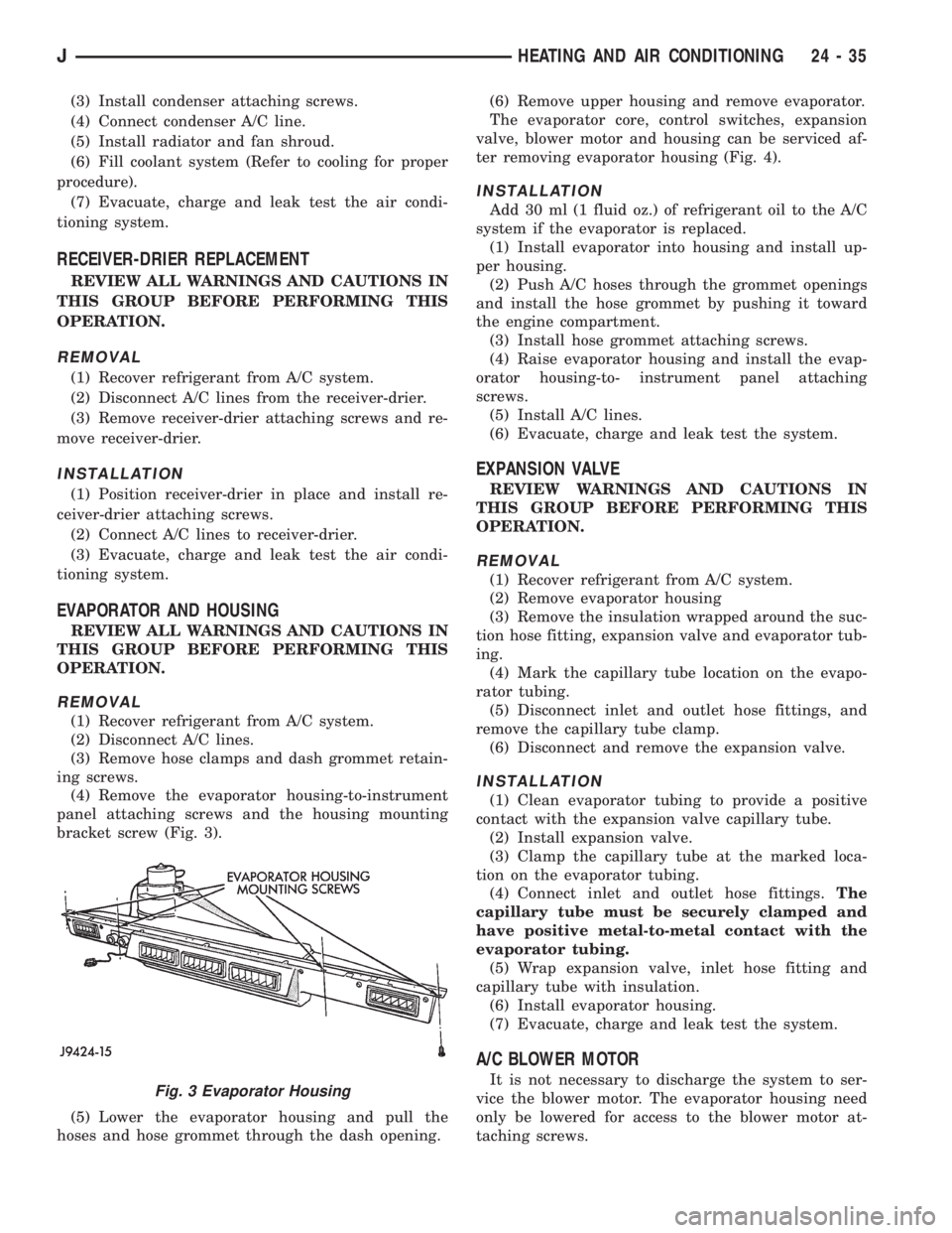
bracket screw (Fig. 3).
(5) Lower the evaporator housing and pull the
hoses and hose grommet through the dash opening.(6) Remove upper housing and remove evaporator.
The evaporator core, control switches, expansion
valve, blower motor and housing can be serviced af-
ter removing evaporator housing (Fig. 4).
INSTALLATION
Add 30 ml (1 fluid oz.) of refrigerant oil to the A/C
system if the evaporator is replaced.
(1) Install evaporator into housing and install up-
per housing.
(2) Push A/C hoses through the grommet openings
and install the hose grommet by pushing it toward
the engine compartment.
(3) Install hose grommet attaching screws.
(4) Raise evaporator housing and install the evap-
orator housing-to- instrument panel attaching
screws.
(5) Install A/C lines.
(6) Evacuate, charge and leak test the system.
EXPANSION VALVE
REVIEW WARNINGS AND CAUTIONS IN
THIS GROUP BEFORE PERFORMING THIS
OPERATION.
REMOVAL
(1) Recover refrigerant from A/C system.
(2) Remove evaporator housing
(3) Remove the insulation wrapped around the suc-
tion hose fitting, expansion valve and evaporator tub-
ing.
(4) Mark the capillary tube location on the evapo-
rator tubing.
(5) Disconnect inlet and outlet hose fittings, and
remove the capillary tube clamp.
(6) Disconnect and remove the expansion valve.
INSTALLATION
(1) Clean evaporator tubing to provide a positive
contact with the expansion valve capillary tube.
(2) Install expansion valve.
(3) Clamp the capillary tube at the marked loca-
tion on the evaporator tubing.
(4) Connect inlet and outlet hose fittings.The
capillary tube must be securely clamped and
have positive metal-to-metal contact with the
evaporator tubing.
(5) Wrap expansion valve, inlet hose fitting and
capillary tube with insulation.
(6) Install evaporator housing.
(7) Evacuate, charge and leak test the system.
A/C BLOWER MOTOR
It is not necessary to discharge the system to ser-
vice the blower motor. The evaporator housing need
only be lowered for access to the blower motor at-
taching screws.Fig. 3 Evaporator Housing
JHEATING AND AIR CONDITIONING 24 - 35
Page 2125 of 2158
- XJ, ANTENNA REMOVE/INSTALL........8F-8
- XJ, GENERAL INFORMATION...........8K-1
- XJ, MULTI-FUNCTION SWITCH..........8J-4
- XJ, MULTI-FUNCTION SWITCH
REMOVE/INSTALL.....................8J-5
- XJ, RADIO REMOVE/INSTALL...........8F-6
- XJ, SOUND BAR REMOVE/INSTALL......8F-8
- XJ, SPEAKERS REMOVE/INSTALL........8F-6
- XJ, TURN SIGNAL/HAZARD WARNING
SYSTEM.............................8J-3
- YJ, ANTENNA REMOVE/INSTALL.......8F-10
- YJ, BUZZER MODULE SCHEMATIC......8U-4
- YJ, GENERAL INFORMATION..........8K-10
- YJ, HAZARD WARNING SYSTEM........8J-4
- YJ, RADIO REMOVE/INSTALL...........8F-9
- YJ, SERVICE PROCEDURES...........8K-17
- YJ, SOUND BAR REMOVE/INSTALL.....8F-10
- YJ, SPEAKERS REMOVE/INSTALL........8F-9
- YJ, TURN SIGNAL SYSTEM............8J-3
- YJ, TURN SIGNAL/HAZARD WARNING
SWITCH REMOVE/INSTALL..............8J-5
30RH/32RH AUTOMATIC TRANSMISSION . . 21-67
30RH/32RH GENERAL SPECIFICATIONS . . 21-335
30RH/32RH IN-VEHICLE SERVICE........21-99
30RH/32RH PRESSURE TEST
SPECIFICATIONS....................21-336
30RH/32RH TORQUE SPECIFICATIONS . . . 21-336
30RH/32RH TRANSMISSION DIAGNOSIS . . 21-70
30RH/32RH TRANSMISSION OVERHAUL . 21-119
30RH/32RH TRANSMISSION REMOVAL
AND INSTALLATION..................21-115
4-CYLINDER ENGINE, ENGINE FIRING
ORDERÐ2.5L.......................8D-32
60-WAY CONNECTOR, POWERTRAIN
CONTROL MODULE (PCM).............14-40
6-CYLINDER ENGINE, AUXILIARY
ELECTRIC COOLING FANÐXJ MODELS
WITH 4.0L...........................7-35
6-CYLINDER ENGINE, ENGINE FIRING
ORDERÐ4.0L.......................8D-32
ABS BRAKE DIAGNOSIS.................5-3
ABS COMPONENT SERVICEABILITY.......5-37
ABS DIAGNOSTIC CONNECTOR.......5-35,5-3
ABS OPERATION AND SERVICE..........5-33
ABS POWER RELAY; ANTI-LOCK BRAKES
(XJ).............................8W-32-1
ABS POWER RELAY; ANTI-LOCK BRAKES
(XJ-RHD).........................8W-32-1
ABS POWER RELAY; ANTI-LOCK BRAKES
(YJ).............................8W-32-1
ABS PUMP MOTOR RELAY; ANTI-LOCK
BRAKES (XJ)......................8W-32-1
ABS PUMP MOTOR RELAY; ANTI-LOCK
BRAKES (XJ-RHD).................8W-32-1
ABS PUMP MOTOR RELAY; ANTI-LOCK
BRAKES (YJ)......................8W-32-1
ABS SYSTEM POWER-UP AND
INITIALIZATION.......................5-35
ABS WARNING LAMP; ANTI-LOCK
BRAKES (XJ)......................8W-32-2
ABS WARNING LAMP; ANTI-LOCK
BRAKES (XJ-RHD).................8W-32-2
ABS WARNING LAMP; ANTI-LOCK
BRAKES (YJ)
......................8W-32-2
ABS WARNING LAMP; INSTRUMENT
CLUSTER (XJ)
.....................8W-40-2
ABS WARNING LAMP; INSTRUMENT
CLUSTER (XJ-RHD)
................8W-40-2
ABS WARNING LAMP; INSTRUMENT
CLUSTER (YJ)
.....................8W-40-2
ABS WARNING LIGHT DISPLAY
...........5-3
ABSOLUTE PRESSURE (MAP) SENSOR,
MANIFOLD; FUEL SYSTEM
.............14-63
ABSOLUTE PRESSURE (MAP) SENSOR,
MANIFOLD; FUEL/IGNITION (YJ)
......8W-30-4
ABSOLUTE PRESSURE (MAP) SENSOR,
MANIFOLD; IGNITION SYSTEMS
....8D-23,8D-5
ABSOLUTE PRESSURE (MAP) SENSOR
TEST, MANIFOLD; FUEL SYSTEM
........14-47
ABSOLUTE PRESSURE (MAP) SENSOR
TEST, MANIFOLD; IGNITION SYSTEMS
....8D-11
ABSOLUTE PRESSURE (MAP)
SENSORÐPCM INPUT, MANIFOLD
.......14-23
ABSOLUTE PRESSURE SENSOR,
MANIFOLD; FUEL/IGNITION (XJ)
......8W-30-4
ABSOLUTE PRESSURE SENSOR,
MANIFOLD; FUEL/IGNITION (XJ-RHD)
. . 8W-30-4ABSORBER, SHOCK; FRONT
SUSPENSION AND AXLE............2-13,2-16
ABSORBER, SHOCK; REAR SUSPENSION
AND AXLES........................3-4,3-7
A/C BLOWER MOTOR.................24-35
A/C COMPONENTS....................24-4
A/C COMPRESSOR; AIR CONDITIONING/
HEATER (YJ)......................8W-42-2
A/C COMPRESSOR CLUTCH............24-15
A/C COMPRESSOR CLUTCH RELAY . 24-15,24-16
A/C CONDENSER.....................24-34
A/C CONTROL REPLACEMENT, HEATER . . . 24-23
A/C OPERATION, HEATER...............24-1
A/C RECIRCULATING DOOR VACUUM
MOTOR REPLACEMENT...............24-27
ACCELERATION SWITCH; ANTI-LOCK
BRAKES (XJ)......................8W-32-1
ACCELERATION SWITCH; ANTI-LOCK
BRAKES (XJ-RHD).................8W-32-1
ACCELERATION SWITCH; ANTI-LOCK
BRAKES (YJ)......................8W-32-1
ACCELERATION SWITCH; BRAKES........5-35
ACCELERATION SWITCH INSTALLATION....5-39
ACCELERATION SWITCH OPERATION......5-37
ACCELERATION SWITCH REMOVAL.......5-39
ACCELERATOR PEDAL.................14-17
ACCELERATOR PEDAL AND THROTTLE
CABLE........................14-17,14-58
ACCESSORY DRIVE BELT...............0-21
ACCESSORY DRIVE BELTS, ENGINE.......7-38
ACCESSORY LAMP AND HEATER
CONTROL PANEL LAMP; INTERIOR
LIGHTING (YJ)....................8W-44-1
ACCUMULATOR PISTONS AND SPRINGS . 21-189
A/C-HEATER BLOWER MOTOR; AIR
CONDITIONING/HEATER (YJ).........8W-42-2
A/C-HEATER SYSTEM; AIR
CONDITIONING/HEATER (XJ).........8W-42-1
A/C-HEATER SYSTEM; AIR
CONDITIONING/HEATER (XJ-RHD).....8W-42-1
ADD-A-TRUNKÐYJ..................23-157
ADJUSTER/MOTORS, POWER SEAT . . . 8R-1,8R-2
ADJUSTER/MOTORS REMOVE/INSTALL,
POWER SEAT........................8R-3
ADJUSTMENT, BRAKELIGHT SWITCH......5-32
ADJUSTMENT, COMPASS VARIATION......8C-5
ADJUSTMENT, DIFFERENTIAL SHIM
PACK MEASUREMENT..................2-43
ADJUSTMENT, DRUM BRAKE............5-57
ADJUSTMENT, FRONT BAND...........21-102
ADJUSTMENT, GEARSHIFT CABLE/
LINKAGE...........................21-71
ADJUSTMENT, PARK INTERLOCK CABLE . 21-195
ADJUSTMENT PROCEDURES,
TRANSMISSION ASSEMBLY...........21-155
ADJUSTMENT, REAR WHEEL SENSOR
INSTALLATION........................5-38
ADJUSTMENT, SHIFT CABLE...........21-195
ADJUSTMENT, SHIFT LINKAGE . . . 21-286,21-309
ADJUSTMENT, TRANSMISSION
THROTTLE CABLE...................21-194
ADJUSTMENT, TRANSMISSION
THROTTLE VALVE CABLE..............21-71
ADJUSTMENT, VALVE BODY ASSEMBLY . . 21-153
ADJUSTMENT (XJ), PARK INTERLOCK
CABLE............................21-101
ADJUSTMENT (XJ), SHIFT CABLE.......21-100
ADJUSTMENT (XJ/YJ), PARKING BRAKE
CABLE TENSIONER....................5-69
ADJUSTMENT (XJ/YJ), THROTTLE VALVE
CABLE............................21-101
ADJUSTMENT (YJ), SHIFT LINKAGE.....21-100
ADJUSTMENTÐMAJOR, DOOR
ALIGNMENT.........................23-41
ADJUSTMENTÐMINOR, DOOR
ALIGNMENT.........................23-37
ADJUSTMENTÐXJ, DOOR LATCH........23-48
ADJUSTMENTÐXJ, HOOD.............23-10
ADJUSTMENTÐXJ, LIFTGATE...........23-63
ADJUSTMENTÐYJ, TAILGATE..........23-121
ADJUSTMENTS, ALIGNMENT
MEASUREMENTS
......................2-8
ADJUSTMENTS, STEERING GEAR
........19-24
AFTERMARKET PAINT AND TRIM
REPAIR PRODUCTSÐXJ
..............23-159
AFTERMARKET PAINT AND TRIM
REPAIR PRODUCTSÐYJ
..............23-160
AIR CLEANER
.......................14-29AIR CLEANER ELEMENT; EMISSION
CONTROL SYSTEMS...................25-7
AIR CLEANER ELEMENT; FUEL SYSTEM . . . 14-59
AIR CLEANER ELEMENT; LUBRICATION
AND MAINTENANCE...................0-18
AIR CLEANER HOUSING...............14-58
AIR CONDITIONING...................24-37
AIR CONDITIONING (A/C) CLUTCH
RELAY.............................14-58
AIR CONDITIONING (A/C) CLUTCH
RELAYÐPCM OUTPUT................14-26
AIR CONDITIONING (A/C) CONTROLSÐ
PCM INPUT.........................14-21
AIR CONDITIONING CONTROLSÐXJ
VEHICLES..........................24-15
AIR CONDITIONING CONTROLSÐYJ
VEHICLES..........................24-16
AIR CONDITIONING, HEATER; AIR
CONDITIONING/HEATER (YJ).........8W-42-2
AIR CONDITIONING OPERATION; AIR
CONDITIONING/HEATER (XJ).........8W-42-2
AIR CONDITIONING OPERATION; AIR
CONDITIONING/HEATER (XJ-RHD).....8W-42-2
AIR CONDITIONING PERFORMANCE
TESTS.............................24-12
AIR CONDITIONING SCHEMATICÐXJ......24-5
AIR CONDITIONING TEST PROCEDURES,
HEATING...........................24-15
AIR CONTROL (IAC) MOTOR, IDLE; FUEL
SYSTEM............................14-62
AIR CONTROL (IAC) MOTOR, IDLE;
FUEL/IGNITION (XJ)................8W-30-2
AIR CONTROL (IAC) MOTOR, IDLE;
FUEL/IGNITION (YJ)................8W-30-2
AIR CONTROL (IAC) MOTOR, IDLE;
FUEL/IGNITION (XJ-RHD)............8W-30-2
AIR CONTROL (IAC) MOTORÐPCM
OUTPUT, IDLE.......................14-27
AIR CONTROL MOTOR TEST, IDLE.......14-49
AIR DEFLECTORÐXJ, COWL
WEATHERSTRIP SEAL/CROSSMEMBER . . . 23-11
AIR DOOR VACUUM MOTOR, FRESH.....24-34
AIR EXHAUST GRILLEÐXJ.............23-25
AIR GAP, SPEED SENSOR...............5-37
AIR INTAKE DUCT, FRESH..............24-34
AIR PRESSURE TEST.................21-74
AIR TEMPERATURE SENSOR, INTAKE;
FUEL/IGNITION (XJ)................8W-30-4
AIR TEMPERATURE SENSOR, INTAKE;
FUEL/IGNITION (YJ)................8W-30-4
AIR TEMPERATURE SENSOR, INTAKE;
FUEL/IGNITION (XJ-RHD)............8W-30-4
AIR TEMPERATURE SENSOR, INTAKE
MANIFOLD; FUEL SYSTEM.............14-60
AIR TEMPERATURE SENSOR, INTAKE
MANIFOLD; IGNITION SYSTEMS....8D-23,8D-5
AIR TEMPERATURE, SENSOR
RESISTANCE (OHMS)ÐCOOLANT
TEMPERATURE SENSOR/MANIFOLD......14-46
AIR TEMPERATURE SENSOR TEST,
INTAKE MANIFOLD; FUEL SYSTEM.......14-46
AIR TEMPERATURE SENSOR TEST,
INTAKE MANIFOLD; IGNITION
SYSTEMS..........................8D-11
AIR TEMPERATURE SENSORÐPCM
INPUT, INTAKE MANIFOLD.............14-22
AIRBAG MODULE.....................8M-1
AIRBAG MODULE HANDLING............8M-2
AIRBAG MODULE REMOVE/INSTALL......8M-3
AIRBAG MODULE REMOVEÐINSTALL....19-49
AIRBAG SYSTEM; RESTRAINT SYSTEMS . . 8M-1
AIRBAG SYSTEM; STEERING...........19-47
AIRBAG SYSTEM SERVICE (DEPLOYED) . . . 8M-2
AIR-CONDITIONER COMPRESSOR........0-21
ALIGNMENT ADJUSTMENTÐMAJOR,
DOOR.............................23-41
ALIGNMENT ADJUSTMENTÐMINOR,
DOOR.............................23-37
ALIGNMENT, FRONT WHEEL..............2-5
ALIGNMENTÐXJ, HEADLAMP...........8L-6
ALIGNMENTÐYJ, HEADLAMP
..........8L-22
ALIGNMENTÐYJ, HOOD
..............23-107
ANCHOR AND BUMPERÐXJ, LIFTGATE
LICENSE PLATE SCREW
...............23-65
ANGLE, GROUND CLEARANCE AND
RAMP
..............................0-11
ANGLE MEASUREMENT, UNIVERSAL
JOINT
..............................16-4
JINDEX 1
Description Group-Page Description Group-Page Description Group-Page
Page 2127 of 2158
BELT TENSIONERÐXJ MODELS WITH
RIGHT HAND DRIVE, AUTOMATIC........7-42
BELT TENSIONÐEXCEPT RIGHT HAND
DRIVE (RHD).........................7-38
BELT TENSIONÐEXCEPT RIGHT HAND
DRIVE (RHD) MODELS.................7-45
BELT TENSIONÐRIGHT HAND DRIVE
(RHD)..............................7-38
BELT/BUCKLEÐXJ, FRONT SHOULDER . . . 23-90
BELT/BUCKLEÐXJ, REAR SHOULDER/
LAP ...............................23-91
BELTLINE SEALÐYJ.................23-142
BELTS, ENGINE ACCESSORY DRIVE.......7-38
BELTSÐYJ, FRONT SHOULDER........23-154
BELTSÐYJ, REAR SHOULDER.........23-154
BENCH BLEEDING, MASTER CYLINDER....5-21
BENCH, GEAR ADJUSTMENTS ON.......19-44
BENCH SEATÐYJ, REAR..............23-153
BEZELÐXJ, INSTRUMENT CLUSTER.....23-80
BEZELÐYJ, INSTRUMENT CLUSTER....23-151
BIN REMOVE/INSTALL, SUNGLASSES
STORAGE...........................8C-7
BLADE REMOVE/INSTALL, WINDSHIELD
WIPER.............................8K-17
BLEEDING, MASTER CYLINDER BENCH....5-21
BLEEDING RECOMMENDATIONS, BRAKE . . . 5-10
BLEEDING (WITH ABS BRAKES), BRAKE . . . 5-11
BLEEDING (WITH STANDARD BRAKES),
BRAKE..............................5-11
BLEEDINGÐBRAKELINES AND HOSES,
BRAKE FLUIDÐBRAKE.................5-10
BLOCK, CYLINDER................9-49,9-91
BLOCK HEATER, ENGINE................7-44
BLOCKSÐTWO-DOOR VEHICLES, FRONT
DOOR SPACER......................23-53
BLOWER MOTOR; AIR CONDITIONING/
HEATER (XJ)......................8W-42-1
BLOWER MOTOR; AIR CONDITIONING/
HEATER (XJ-RHD)..................8W-42-1
BLOWER MOTOR; HEATING AND AIR
CONDITIONING......................24-17
BLOWER MOTOR, A/C.................24-35
BLOWER MOTOR, A/C-HEATER; AIR
CONDITIONING/HEATER (YJ).........8W-42-2
BLOWER MOTOR (HEATING)...........24-33
BLOWER MOTOR RESISTORS
REPLACEMENT......................24-31
BLOWER MOTOR SWITCH.............24-16
BLOWER MOTOR/AIR DOOR MOTOR
SWITCH REPLACEMENT...............24-32
BLOWER MOTOR/FAN REPLACEMENT....24-24
BODY ASSEMBLY AND ADJUSTMENT,
VALVE ............................21-153
BODY CHECK BALL DIMENSIONS, AW-4
VALVE ............................21-341
BODY CODE LETTERS, JEEP..............5-2
BODY LUBRICANT SPECIFICATIONS.......0-33
BODY OVERHAUL, TRANSMISSION
VALVE ............................21-250
BODY REMOVAL, TRANSMISSION VALVE . 21-186
BODY REMOVAL, VALVE..............21-104
BODY SERVICE INFORMATION, GENERAL . . 23-1
BODY SERVICE, VALVE...............21-104
BODY SIDE MOLDING/CLADDINGÐXJ....23-20
BODY SIDE STEP MOLDINGÐYJ.......23-115
BODY SOLENOIDS, TRANSMISSION
VALVE ............................21-184
BODY STRIPES/DECALSÐXJ...........23-21
BODY STRIPES/DECALSÐYJ..........23-116
BODY, THROTTLE...............14-33,14-64
BOLT IDENTIFICATION..............Intro.-14
BOLT STRENGTH..................Intro.-15
BOOSTER CHECK VALVE TEST, POWER.....5-9
BOOSTER INSTALLATION (XJ WITH
ABS), POWER BRAKE..................5-27
BOOSTER INSTALLATION (XJ WITHOUT
ABS), POWER BRAKE..................5-30
BOOSTER INSTALLATION (YJ), POWER
BRAKE..............................5-30
BOOSTER, MASTER CYLINDER/POWER
BRAKE
..............................5-34
BOOSTER OPERATION, POWER BRAKE
....5-23
BOOSTER REMOVAL (XJ WITH ABS),
POWER BRAKE
.......................5-24
BOOSTER REMOVAL (XJ WITHOUT ABS),
POWER BRAKE
.......................5-29
BOOSTER REMOVAL (YJ), POWER
BRAKE
..............................5-30BOOSTER TEST, MASTER CYLINDER/
POWER..............................5-8
BOOSTER VACUUM TEST, POWER.........5-9
BOOSTERÐBRAKE PEDALÐ
BRAKELIGHT SWITCH, POWER BRAKE....5-22
BORES, HONING CYLINDER..............9-2
BOX LAMP, GLOVE; INTERIOR LIGHTING
(XJ).............................8W-44-1
BOX LAMP, GLOVE; INTERIOR LIGHTING
(XJ-RHD).........................8W-44-1
BOXÐYJ, GLOVE...................23-152
BRACKET REPLACEMENTÐXJ, INTERIOR
REARVIEW MIRROR SUPPORT..........23-68
BRACKETÐYJ, REARVIEW MIRROR
RETAINING........................23-144
BRACKETSÐXJ, SPARE TIRE/WHEEL
HOLDDOWN AND FLOOR..............23-98
BRAKE ADJUSTMENT, DRUM............5-57
BRAKE BLEEDING RECOMMENDATIONS....5-10
BRAKE BLEEDING (WITH ABS BRAKES)....5-11
BRAKE BLEEDING (WITH STANDARD
BRAKES)............................5-11
BRAKE BOOSTER INSTALLATION (XJ
WITH ABS), POWER...................5-27
BRAKE BOOSTER INSTALLATION (XJ
WITHOUT ABS), POWER................5-30
BRAKE BOOSTER INSTALLATION (YJ),
POWER.............................5-30
BRAKE BOOSTER, MASTER CYLINDER/
POWER.............................5-34
BRAKE BOOSTER OPERATION, POWER....5-23
BRAKE BOOSTER REMOVAL (XJ WITH
ABS), POWER........................5-24
BRAKE BOOSTER REMOVAL (XJ
WITHOUT ABS), POWER................5-29
BRAKE BOOSTER REMOVAL (YJ),
POWER.............................5-30
BRAKE BOOSTERÐBRAKE PEDALÐ
BRAKELIGHT SWITCH, POWER...........5-22
BRAKE CABLE TENSIONER ADJUSTMENT
(XJ/YJ), PARKING.....................5-69
BRAKE CABLE TENSIONER
REPLACEMENT (XJ), PARKING...........5-66
BRAKE CHECK, PRELIMINARY............5-4
BRAKE COMPONENTS...................5-1
BRAKE DIAGNOSIS, ABS.................5-3
BRAKE DIAGNOSIS, SERVICE.............5-4
BRAKE DRUM REFINISHING.............5-58
BRAKE FLUID CONTAMINATION.......5-10,5-7
BRAKE FLUID LEVEL...................5-10
BRAKE FLUID, RECOMMENDED..........5-10
BRAKE FLUID/LUBRICANTS/CLEANING
SOLVENTS............................5-2
BRAKE FLUIDÐBRAKE BLEEDINGÐ
BRAKELINES AND HOSES...............5-10
BRAKE FRONT CABLE REPLACEMENT
(YJ), PARKING........................5-67
BRAKE HANDLE COVERÐXJ, PARKING . . . 23-94
BRAKE LEVER INSTALLATION (XJ WITH
FULL CONSOLE), PARKING..............5-64
BRAKE LEVER INSTALLATION (XJ WITH
MINI CONSOLE), PARKING..............5-63
BRAKE LEVER INSTALLATION (XJ
WITHOUT CONSOLE), PARKING..........5-65
BRAKE LEVER REMOVAL (XJ WITH FULL
CONSOLE), PARKING..................5-63
BRAKE LEVER REMOVAL (XJ WITH MINI
CONSOLE), PARKING..................5-62
BRAKE LEVER REMOVAL (XJ WITHOUT
CONSOLE), PARKING
..................5-64
BRAKE MALFUNCTIONS, DIAGNOSING
PARKING
.............................5-8
BRAKE NOISE
.........................5-7
BRAKE OPERATION, PARKING
...........5-60
BRAKE OVERHAUL, SECOND
..........21-241
BRAKE PACK REQUIREMENTS, AW-4
CLUTCH
...........................21-341
BRAKE PEDAL BUSHINGS, CLUTCH
.......0-22
BRAKE PEDAL INSTALLATION
............5-31
BRAKE PEDAL INSTALLATION (YJ),
PARKING
............................5-66
BRAKE PEDAL REMOVAL
...............5-31
BRAKE PEDAL REMOVAL (YJ), PARKING
. . . 5-66
BRAKE PEDAL TRAVEL SENSOR;
ANTI-LOCK BRAKES (YJ)
............8W-32-1
BRAKE PISTON AND TRANSMISSION
CASE OVERHAUL, FIRST-REVERSE
......21-247BRAKE REAR CABLE REPLACEMENT
(XJ), PARKING........................5-67
BRAKE REAR CABLE REPLACEMENT
(YJ), PARKING........................5-68
BRAKE ROTOR REFINISHING, DISC.......5-53
BRAKE ROTOR RUNOUT, DISC...........5-52
BRAKE ROTOR THICKNESS, DISC........5-52
BRAKE SAFETY PRECAUTIONS............5-2
BRAKE SWITCH......................14-59
BRAKE SWITCH INPUT; ANTI-LOCK
BRAKES (XJ)......................8W-32-2
BRAKE SWITCH INPUT; ANTI-LOCK
BRAKES (XJ-RHD).................8W-32-2
BRAKE SWITCH INPUT; ANTI-LOCK
BRAKES (YJ)......................8W-32-2
BRAKE SWITCH INPUT; FUEL/IGNITION
(XJ).............................8W-30-5
BRAKE SWITCH INPUT; FUEL/IGNITION
(YJ).............................8W-30-5
BRAKE SWITCH INPUT; FUEL/IGNITION
(XJ-RHD).........................8W-30-5
BRAKE SWITCH, PARKING..............5-68
BRAKE SWITCHÐPCM INPUT..........14-22
BRAKE SYSTEM, POWER...............0-30
BRAKE TORQUE SPECIFICATIONS.........5-70
BRAKE WARNING LAMP; INSTRUMENT
CLUSTER (XJ).....................8W-40-2
BRAKE WARNING LAMP; INSTRUMENT
CLUSTER (XJ-RHD)................8W-40-2
BRAKE WARNING LAMP; INSTRUMENT
CLUSTER (YJ)......................8W-40-2
BRAKE WARNING LIGHTS................5-1
BRAKELIGHT SWITCH ADJUSTMENT......5-32
BRAKELIGHT SWITCH INSTALLATION......5-32
BRAKELIGHT SWITCH REMOVAL.........5-32
BRAKELINE CHARTS...................5-12
BRAKELINES AND HOSES...............5-12
BRAKELINING, CONTAMINATED...........5-7
BRAKELINING MATERIAL................5-1
BRAKES (ABS), ANTILOCK...............5-1
BRAKES, DISC........................5-45
BRAKES DO NOT HOLD AFTER DRIVING
THROUGH DEEP WATER PUDDLES........5-7
BRAKES, DRUM......................5-55
BRAKES, PARKING....................5-60
BRAKESHOE INSTALLATION, DISC........5-47
BRAKESHOE INSTALLATION, DRUM.......5-55
BRAKESHOE REMOVAL, DISC............5-46
BRAKESHOE REMOVAL, DRUM...........5-55
BRAKING MODE, ABS OPERATION IN
ANTILOCK...........................5-36
BRAKING MODE, ABS OPERATION IN
NORMAL............................5-35
BREAK-IN, ENGINE....................0-15
BRUSH GUARDÐXJ...................23-3
BUCKET SEAT CUSHION AND COVERÐ
XJ ................................23-81
BUCKET SEAT PLATFORMÐXJ..........23-82
BUCKET SEATBACK COVER AND
FRAMEÐXJ.........................23-81
BUCKET SEATSÐXJ, FRONT............23-81
BUCKET SEATSÐYJ.................23-153
BULB APPLICATIONÐXJ VEHICLES......8L-18
BULB APPLICATIONÐYJ VEHICLES......8L-32
BULB REMOVE/INSTALL, READING/
COURTESY LAMP.....................8C-8
BULB REPLACEMENTÐXJ, BACK-UP/
REAR TURN SIGNAL/TAIL LAMP.........8L-12
BULB REPLACEMENTÐXJ, FRONT
PARK/TURN SIGNAL LAMP..............8L-9
BULB REPLACEMENTÐXJ, HEADLAMP....8L-7
BULB REPLACEMENTÐXJ, SIDE
MARKER LAMP......................8L-10
BULB REPLACEMENTÐXJ, UNDERHOOD
LAMP..............................8L-13
BULB REPLACEMENTÐYJ, BACK-UP/
REAR TURN SIGNAL/TAIL LAMP.........8L-28
BULB REPLACEMENTÐYJ, FRONT
PARK/TURN SIGNAL LAMP.............8L-25
BULB REPLACEMENTÐYJ, HEADLAMP . . . 8L-23
BULB REPLACEMENTÐYJ, SIDE
MARKER LAMP
......................8L-25
BULB REPLACEMENTÐYJ, UNDERHOOD
LAMP
..............................8L-29
BULB REPLACEMENTÐYJ VEHICLES,
HARDTOP DOME/CARGO LAMP
.........8L-31
BUMPER, FRONT
.................13-16,13-5
BUMPER, REAR
..................13-16,13-8
JINDEX 3
Description Group-Page Description Group-Page Description Group-Page
Page 2132 of 2158
DIAGRAM INDEX; AIR CONDITIONING/
HEATER (XJ-RHD)..................8W-42-2
DIAGRAM INDEX; AIR CONDITIONING/
HEATER (YJ)...............8W-42-1,8W-42-2
DIAGRAM INDEX; ANTI-LOCK BRAKES
(XJ).............................8W-32-3
DIAGRAM INDEX; ANTI-LOCK BRAKES
(XJ-RHD).........................8W-32-3
DIAGRAM INDEX; ANTI-LOCK BRAKES
(YJ).............................8W-32-2
DIAGRAM INDEX; CHARGING SYSTEM
(XJ).............................8W-20-1
DIAGRAM INDEX; CHARGING SYSTEM
(XJ-RHD).........................8W-20-1
DIAGRAM INDEX; CHARGING SYSTEM
(YJ).............................8W-20-1
DIAGRAM INDEX; FRONT LIGHTING (XJ) . 8W-50-2
DIAGRAM INDEX; FRONT LIGHTING
(XJ-RHD).........................8W-50-3
DIAGRAM INDEX; FRONT LIGHTING (YJ) . 8W-50-2
DIAGRAM INDEX; FUEL/IGNITION (YJ) . . 8W-30-5
DIAGRAM INDEX; FUSE/FUSE BLOCK
(XJ).............................8W-10-1
DIAGRAM INDEX; FUSE/FUSE BLOCK
(XJ-RHD).........................8W-10-1
DIAGRAM INDEX; FUSE/FUSE BLOCK
(YJ).............................8W-10-1
DIAGRAM INDEX; GROUND
DISTRIBUTION (XJ)................8W-15-1
DIAGRAM INDEX; GROUND
DISTRIBUTION (XJ-RHD)............8W-15-1
DIAGRAM INDEX; GROUND
DISTRIBUTION (YJ)..................8W-15-1
DIAGRAM INDEX; HEATED REAR
WINDOW (XJ).....................8W-48-1
DIAGRAM INDEX; HEATED REAR
WINDOW (XJ-RHD).................8W-48-1
DIAGRAM INDEX; HEATED REAR
WINDOW (YJ).....................8W-48-1
DIAGRAM INDEX; HORN/CIGAR LIGHTER . . . 8E-1
DIAGRAM INDEX; HORN/CIGAR LIGHTER
(YJ).............................8W-41-1
DIAGRAM INDEX; INSTRUMENT
CLUSTER (XJ).............8W-40-1,8W-40-3
DIAGRAM INDEX; INSTRUMENT
CLUSTER (XJ-RHD)................8W-40-3
DIAGRAM INDEX; INSTRUMENT
CLUSTER (YJ).....................8W-40-2
DIAGRAM INDEX; INTERIOR LIGHTING
(XJ).............................8W-44-2
DIAGRAM INDEX; INTERIOR LIGHTING
(XJ-RHD).........................8W-44-2
DIAGRAM INDEX; INTERIOR LIGHTING
(YJ).............................8W-44-2
DIAGRAM INDEX; OVERHEAD CONSOLE
(XJ).............................8W-49-1
DIAGRAM INDEX; OVERHEAD CONSOLE
(XJ-RHD).........................8W-49-1
DIAGRAM INDEX; POWER DISTRIBUTION
(XJ).............................8W-11-1
DIAGRAM INDEX; POWER DISTRIBUTION
(XJ-RHD).........................8W-11-1
DIAGRAM INDEX; POWER DISTRIBUTION
(YJ).............................8W-11-1
DIAGRAM INDEX; POWER DOOR LOCKS
(XJ)
.............................8W-61-1
DIAGRAM INDEX; POWER DOOR LOCKS
(XJ-RHD)
.........................8W-61-1
DIAGRAM INDEX; POWER MIRRORS
(XJ)
.............................8W-62-1
DIAGRAM INDEX; POWER MIRRORS
(XJ-RHD)
.........................8W-62-1
DIAGRAM INDEX; POWER SEAT (XJ)
. . . 8W-63-1
DIAGRAM INDEX; POWER SEAT
(XJ-RHD)
.........................8W-63-1
DIAGRAM INDEX; POWER WINDOWS
(XJ)
.............................8W-60-2
DIAGRAM INDEX; POWER WINDOWS
(XJ-RHD)
.........................8W-60-2
DIAGRAM INDEX; REAR LIGHTING (XJ)
. 8W-51-1
DIAGRAM INDEX; REAR LIGHTING
(XJ-RHD)
.........................8W-51-1
DIAGRAM INDEX; REAR LIGHTING (YJ)
. 8W-51-1
DIAGRAM INDEX; STARTING SYSTEM
(XJ)
.............................8W-21-1
DIAGRAM INDEX; STARTING SYSTEM
(XJ-RHD)
.........................8W-21-1DIAGRAM INDEX; STARTING SYSTEM
(YJ).............................8W-21-1
DIAGRAM INDEX; TRAILER TOW (XJ) . . 8W-54-1
DIAGRAM INDEX; TRAILER TOW
(XJ-RHD).........................8W-54-1
DIAGRAM INDEX; TRANSMISSION
CONTROLS (XJ)...................8W-31-1
DIAGRAM INDEX; TRANSMISSION
CONTROLS (XJ-RHD)...............8W-31-1
DIAGRAM INDEX; TRANSMISSION
CONTROLS (YJ)...................8W-31-1
DIAGRAM INDEX; TURN SIGNALS (XJ) . 8W-52-1
DIAGRAM INDEX; TURN SIGNALS
(XJ-RHD).........................8W-52-1
DIAGRAM INDEX; TURN SIGNALS (YJ) . 8W-52-1
DIAGRAM INDEX; VEHICLE SPEED
CONTROL (XJ)....................8W-33-1
DIAGRAM INDEX; VEHICLE SPEED
CONTROL (XJ-RHD)................8W-33-1
DIAGRAM INDEX; WIPERS (XJ).......8W-53-2
DIAGRAM INDEX; WIPERS (XJ-RHD) . . . 8W-53-2
DIAGRAM INDEX; WIPERS (YJ).......8W-53-2
DIAGRAM INDEX; FUEL/IGNITION
(XJ-RHD).........................8W-30-5
DIAGRAM INDEXÐ2.5L ENGINE;
FUEL/IGNITION (XJ)................8W-30-6
DIAGRAM INDEXÐ4.0L ENGINE;
FUEL/IGNITION (XJ)................8W-30-6
DIFFERENTIAL AND PINION
MEASUREMENT.......................2-40
DIFFERENTIAL ASSEMBLY; FRONT
SUSPENSION AND AXLE.................2-38
DIFFERENTIAL ASSEMBLY; REAR
SUSPENSION AND AXLES...............3-21
DIFFERENTIAL DISASSEMBLY; FRONT
SUSPENSION AND AXLE................2-35
DIFFERENTIAL DISASSEMBLY; REAR
SUSPENSION AND AXLES...............3-18
DIFFERENTIAL INSTALLATION............2-44
DIFFERENTIAL, LIMITED SLIP............3-10
DIFFERENTIAL MEASUREMENT AND
INSTALLATION........................3-25
DIFFERENTIAL OVERHAUL..............3-46
DIFFERENTIAL REMOVAL; FRONT
SUSPENSION AND AXLE................2-34
DIFFERENTIAL REMOVAL; REAR
SUSPENSION AND AXLES...............3-18
DIFFERENTIAL SERVICE................3-34
DIFFERENTIAL SHIM PACK
MEASUREMENT AND ADJUSTMENT.......2-43
DIFFERENTIAL, TRAC-LOK..............3-45
DIMENSION DATA, VEHICLE.....Intro.-5,Intro.-6
DIMENSIONS, AW-4 VALVE BODY CHECK
BALL.............................21-341
DIMENSIONS, DESIGNATIONS,
LABELS/PLATES, CODES..............Intro.-1
DIMENSIONS, FRAME.............13-13,13-1
DIMMER SWITCH REMOVE/INSTALL,
HEADLAMP OR PANEL................8E-42
DIMMER SWITCH REPLACEMENTÐYJ,
HEADLAMP.........................8L-26
DIMMING MODULE; FRONT LIGHTING
(XJ-RHD).........................8W-50-1
DIODE REPLACEMENT; WIRING
DIAGRAMSÐGENERAL INFORMATION
(XJ)...............................8W-8
DIRECT CLUTCH OVERHAUL...........21-228
DISASSEMBLY AND INSPECTION, VALVE
BODY.............................21-147
DISASSEMBLY AND OVERHAUL,
TRANSFER CASE..............21-289,21-310
DISASSEMBLY AND OVERHAUL,
TRANSMISSION.................21-37,21-5
DISASSEMBLY, CALIPER................5-48
DISASSEMBLY, DIFFERENTIAL; FRONT
SUSPENSION AND AXLE................2-35
DISASSEMBLY, DIFFERENTIAL; REAR
SUSPENSION AND AXLES...............3-18
DISASSEMBLY, TRANSMISSION . . 21-119,21-201
DISASSEMBLYÐCOLUMN OR CONSOLE
SHIFT..............................19-60
DISC AND PLATE THICKNESS, AW-4
CLUTCH...........................21-338
DISC BRAKE ROTOR REFINISHING
........5-53
DISC BRAKE ROTOR RUNOUT
...........5-52
DISC BRAKE ROTOR THICKNESS
.........5-52
DISC BRAKES
........................5-45
DISC BRAKESHOE INSTALLATION
.........5-47DISC BRAKESHOE REMOVAL............5-46
DISC INSTALLATION, CLUTCH COVER.....6-10
DISC REMOVAL, CLUTCH COVER.........6-10
DISC RUNOUT, CLUTCH COVER...........6-3
DISCHARGE (ESD) SENSITIVE DEVICES,
ELECTROSTATIC; WIRING
DIAGRAMSÐGENERAL INFORMATION
(XJ)...............................8W-2
DISCONNECT AXLEÐYJ VEHICLES,
VACUUM............................2-27
DISCONNECT AXLE/SHIFT MOTOR
DIAGNOSIS..........................2-29
DISCONNECT AXLE/SHIFT MOTOR
DIAGNOSIS (CONT'D)..................2-30
DISPLAY, ABS WARNING LIGHT...........5-3
DISPLAY SYMBOLS, INTERNATIONAL
VEHICLE CONTROL..................Intro.-5
DISPLAY SYMBOLS, VEHICLE CONTROL . Intro.-10
DISPOSALÐXJ, LIFTGATE SUPPORT
ROD CYLINDER......................23-63
DISTRIBUTOR.......................8D-19
DISTRIBUTOR CAP....................8D-7
DISTRIBUTOR CAP AND ROTOR,
IGNITION CABLES.....................0-20
DISTRIBUTOR ROTOR.................8D-8
DISTRIBUTORS.......................8D-4
DOME LAMP, CARGO LAMP; INTERIOR
LIGHTING (XJ-RHD)................8W-44-1
DOME LAMP, CARGO LAMP, COURTESY
LAMPS; INTERIOR LIGHTING (XJ).....8W-44-1
DOME LAMP REPLACEMENTÐXJ.........8L-17
DOME LAMPÐXJ....................23-93
DOME LAMPS, COURTESY LAMPS;
INTERIOR LIGHTING (YJ)............8W-44-1
DOME/CARGO LAMP BULB
REPLACEMENTÐYJ VEHICLES,
HARDTOP..........................8L-31
DOME/COURTESY LAMP SERVICE
INFORMATIONÐXJ...................8L-16
DOME/COURTESY LAMP SERVICE
INFORMATIONÐYJ...................8L-31
DOME/COURTESY LAMP TROUBLE
DIAGNOSISÐXJ.....................8L-16
DOME/COURTESY LAMP TROUBLE
DIAGNOSISÐYJ.....................8L-31
DOOR ALIGNMENT ADJUSTMENTÐ
MAJOR............................23-41
DOOR ALIGNMENT ADJUSTMENTÐ
MINOR.............................23-37
DOOR ASSIST HANDLEÐYJ, FULL-
METAL............................23-136
DOOR BUMPERSÐXJ, FUEL FILLER.....23-27
DOOR CONTROL CABLES, VENT.........24-32
DOOR EDGE GUARD/EDGE PROTECTOR
STRIPÐXJ.........................23-54
DOOR EXTERNAL HANDLEÐXJ.........23-48
DOOR FRAME GLASS CHANNEL
REPLACEMENTÐYJ.................23-142
DOOR HINGE/HINGE PIN
REPLACEMENTÐXJ..................23-52
DOOR HINGESÐYJ, FULL-METAL.......23-140
DOOR INSIDE LATCH RELEASE AND
LOCK RODSÐXJ.....................23-50
DOOR JAMB SWITCH, DRIVER'S.....8U-1,8U-2
DOOR KEY LOCK CYLINDERÐXJ........23-47
DOOR KEY LOCK CYLINDERÐYJ,
FULL-METAL.......................23-139
DOOR LATCH ADJUSTMENTÐXJ........23-48
DOOR LATCH EXTERNAL RELEASE
HANDLEÐYJ, FULL-METAL............23-140
DOOR LATCH INSIDE RELEASE AND
LOCK HANDLEÐYJ, FULL-METAL.......23-137
DOOR LATCH STRIKERÐYJ, HALF-
METAL............................23-135
DOOR LATCHÐXJ....................23-49
DOOR LATCHÐYJ, FULL-METAL........23-140
DOOR LOCKS, POWER; POWER DOOR
LOCKS (XJ).......................8W-61-1
DOOR LOCKS, POWER; POWER DOOR
LOCKS (XJ-RHD)
..................8W-61-1
DOOR MIRROR (EXTERNAL)ÐYJ, HALF
METAL
............................23-121
DOOR MOTOR SWITCH REPLACEMENT,
BLOWER MOTOR/AIR
.................24-32
DOOR OPENER STORAGE, REMOTE
GARAGE
............................8C-1
DOOR OPENING WEATHERSTRIP
SEALSÐXJ, DOOR WINDOW GLASS
.....23-55
8 INDEXJ
Description Group-Page Description Group-Page Description Group-Page