1995 JEEP YJ blower motor
[x] Cancel search: blower motorPage 907 of 2158
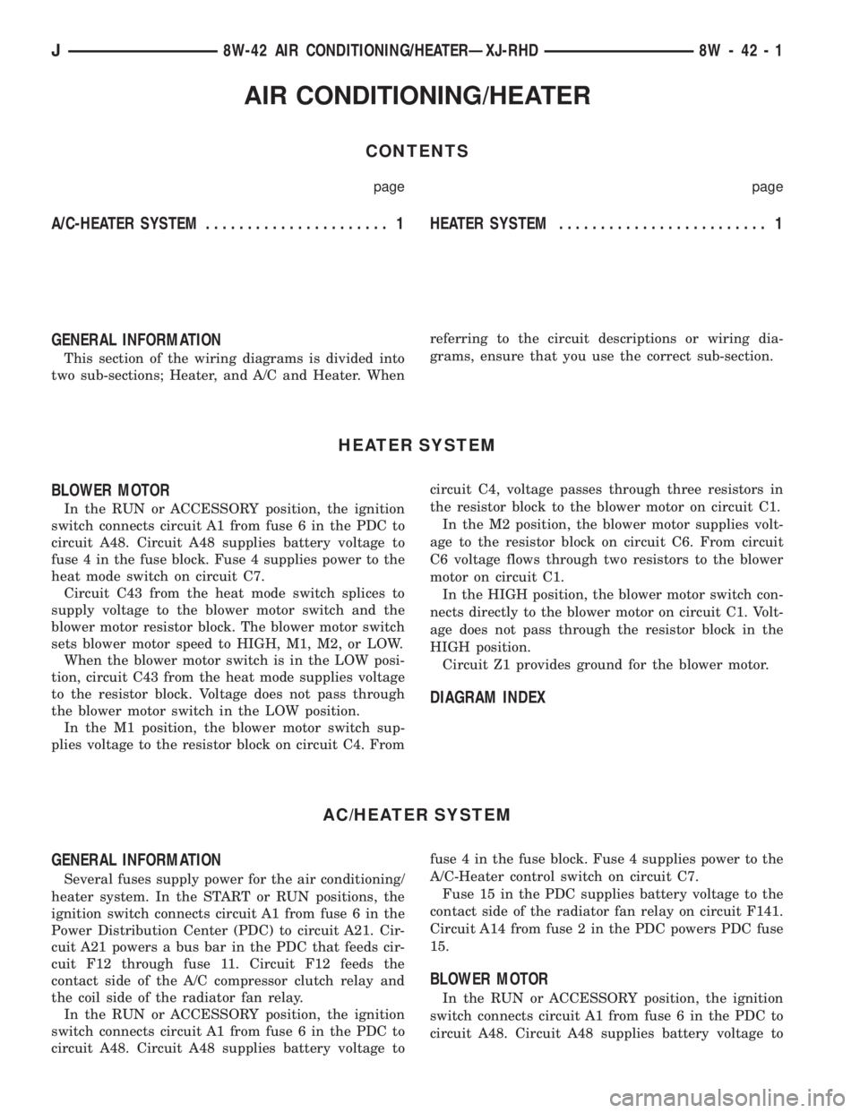
AIR CONDITIONING/HEATER
CONTENTS
page page
A/C-HEATER SYSTEM...................... 1 HEATERSYSTEM......................... 1
GENERAL INFORMATION
This section of the wiring diagrams is divided into
two sub-sections; Heater, and A/C and Heater. Whenreferring to the circuit descriptions or wiring dia-
grams, ensure that you use the correct sub-section.
HEATER SYSTEM
BLOWER MOTOR
In the RUN or ACCESSORY position, the ignition
switch connects circuit A1 from fuse 6 in the PDC to
circuit A48. Circuit A48 supplies battery voltage to
fuse 4 in the fuse block. Fuse 4 supplies power to the
heat mode switch on circuit C7.
Circuit C43 from the heat mode switch splices to
supply voltage to the blower motor switch and the
blower motor resistor block. The blower motor switch
sets blower motor speed to HIGH, M1, M2, or LOW.
When the blower motor switch is in the LOW posi-
tion, circuit C43 from the heat mode supplies voltage
to the resistor block. Voltage does not pass through
the blower motor switch in the LOW position.
In the M1 position, the blower motor switch sup-
plies voltage to the resistor block on circuit C4. Fromcircuit C4, voltage passes through three resistors in
the resistor block to the blower motor on circuit C1.
In the M2 position, the blower motor supplies volt-
age to the resistor block on circuit C6. From circuit
C6 voltage flows through two resistors to the blower
motor on circuit C1.
In the HIGH position, the blower motor switch con-
nects directly to the blower motor on circuit C1. Volt-
age does not pass through the resistor block in the
HIGH position.
Circuit Z1 provides ground for the blower motor.
DIAGRAM INDEX
AC/HEATER SYSTEM
GENERAL INFORMATION
Several fuses supply power for the air conditioning/
heater system. In the START or RUN positions, the
ignition switch connects circuit A1 from fuse 6 in the
Power Distribution Center (PDC) to circuit A21. Cir-
cuit A21 powers a bus bar in the PDC that feeds cir-
cuit F12 through fuse 11. Circuit F12 feeds the
contact side of the A/C compressor clutch relay and
the coil side of the radiator fan relay.
In the RUN or ACCESSORY position, the ignition
switch connects circuit A1 from fuse 6 in the PDC to
circuit A48. Circuit A48 supplies battery voltage tofuse 4 in the fuse block. Fuse 4 supplies power to the
A/C-Heater control switch on circuit C7.
Fuse 15 in the PDC supplies battery voltage to the
contact side of the radiator fan relay on circuit F141.
Circuit A14 from fuse 2 in the PDC powers PDC fuse
15.
BLOWER MOTOR
In the RUN or ACCESSORY position, the ignition
switch connects circuit A1 from fuse 6 in the PDC to
circuit A48. Circuit A48 supplies battery voltage to
J8W-42 AIR CONDITIONING/HEATERÐXJ-RHD 8W - 42 - 1
Page 908 of 2158
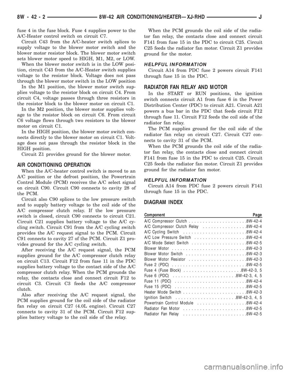
fuse 4 in the fuse block. Fuse 4 supplies power to the
A/C-Heater control switch on circuit C7.
Circuit C43 from the A/C-heater switch splices to
supply voltage to the blower motor switch and the
blower motor resistor block. The blower motor switch
sets blower motor speed to HIGH, M1, M2, or LOW.
When the blower motor switch is in the LOW posi-
tion, circuit C43 from the A/C-Heater switch supplies
voltage to the resistor block. Voltage does not pass
through the blower motor switch in the LOW position
In the M1 position, the blower motor switch sup-
plies voltage to the resistor block on circuit C4. From
circuit C4, voltage passes through three resistors in
the resistor block to the blower motor on circuit C1.
In the M2 position, the blower motor supplies volt-
age to the resistor block on circuit C6. From circuit
C6 voltage flows through two resistors to the blower
motor on circuit C1.
In the HIGH position, the blower motor switch con-
nects directly to the blower motor on circuit C1. Volt-
age does not pass through the resistor block in the
HIGH position.
Circuit Z1 provides ground for the blower motor.
AIR CONDITIONING OPERATION
When the A/C-heater control switch is moved to an
A/C position or the defrost position, the Powertrain
Control Module (PCM) receives the A/C select signal
on circuit C90. Circuit C90 connects to cavity 28 of
the PCM.
Circuit also C90 splices to the low pressure switch
and to supply battery voltage to the coil side of the
A/C compressor clutch relay. If the low pressure
switch is closed, circuit C90 connects to circuit C21.
Circuit C21 supplies battery voltage to the A/C cy-
cling switch. Circuit C91 from the A/C cycling switch
provides the A/C request signal to the PCM. Circuit
C91 connects to cavity 27 of the PCM. Circuit Z1 pro-
vides ground for the A/C cycling switch.
After receiving the A/C request signal, the PCM
supplies ground for the A/C compressor clutch relay
on circuit C13. Circuit F12 from fuse 11 in the PDC
supplies battery voltage to the contact side of the A/C
compressor clutch relay. When the PCM grounds the
relay, the contacts close and connect circuit F12 to
circuit C3. Circuit C3 feeds the A/C compressor
clutch.
Also after receiving the A/C request signal, the
PCM supplies ground for the coil side of the radiator
fan relay on circuit C27 (4.0L engine). Circuit C27
connects to cavity 31 of the PCM. Circuit F12 sup-
plies battery voltage to the coil side of the relay.When the PCM grounds the coil side of the radia-
tor fan relay, the contacts close and connect circuit
F141 from fuse 15 in the PDC to circuit C25. Circuit
C25 feeds the radiator fan motor. Circuit Z1 provides
ground for the motor.
HELPFUL INFORMATION
Circuit A14 from PDC fuse 2 powers circuit F141
through fuse 15 in the PDC.
RADIATOR FAN RELAY AND MOTOR
In the START or RUN positions, the ignition
switch connects circuit A1 from fuse 6 in the Power
Distribution Center (PDC) to circuit A21. Circuit A21
powers a bus bar in the PDC that feeds circuit F12
through fuse 11. Circuit F12 feeds the coil side of the
radiator fan relay.
The PCM supplies ground for the coil side of the
radiator fan relay on circuit C27. Circuit C27 con-
nects to cavity 31 of the PCM.
When the PCM grounds the coil side of the radia-
tor fan relay, the contacts close and connect circuit
F141 from fuse 15 in the PDC to circuit C25. Circuit
C25 feeds the radiator fan motor. Circuit Z1 provides
ground for the radiator fan motor.
HELPFUL INFORMATION
Circuit A14 from PDC fuse 2 powers circuit F141
through fuse 15 in the PDC.
DIAGRAM INDEX
Component Page
A/C Compressor Clutch.....................8W-42-4
A/C Compressor Clutch Relay................8W-42-4
A/C Cycling Switch.......................8W-42-4
A/C Low Pressure Switch...................8W-42-4
A/C Mode Select Switch....................8W-42-5
Blower Motor...........................8W-42-3
Blower Motor Switch......................8W-42-3
Blower Motor Resistor.....................8W-42-3
Fuse 2 (PDC)...........................8W-42-5
Fuse 4 (Fuse Block).....................8W-42-3, 5
Fuse 6 (PDC).......................8W-42-3, 4, 5
Fuse 11 (PDC)..........................8W-42-4
Fuse 15 (PDC)..........................8W-42-5
Heater Mode Switch.......................8W-42-3
Ignition Switch......................8W-42-3, 4, 5
Powertrain Control Module..................8W-42-4
Radiator Fan Motor.......................8W-42-5
Radiator Fan Relay.......................8W-42-5
8W - 42 - 2 8W-42 AIR CONDITIONING/HEATERÐXJ-RHDJ
Page 1085 of 2158
SPLICE LOCATIONS
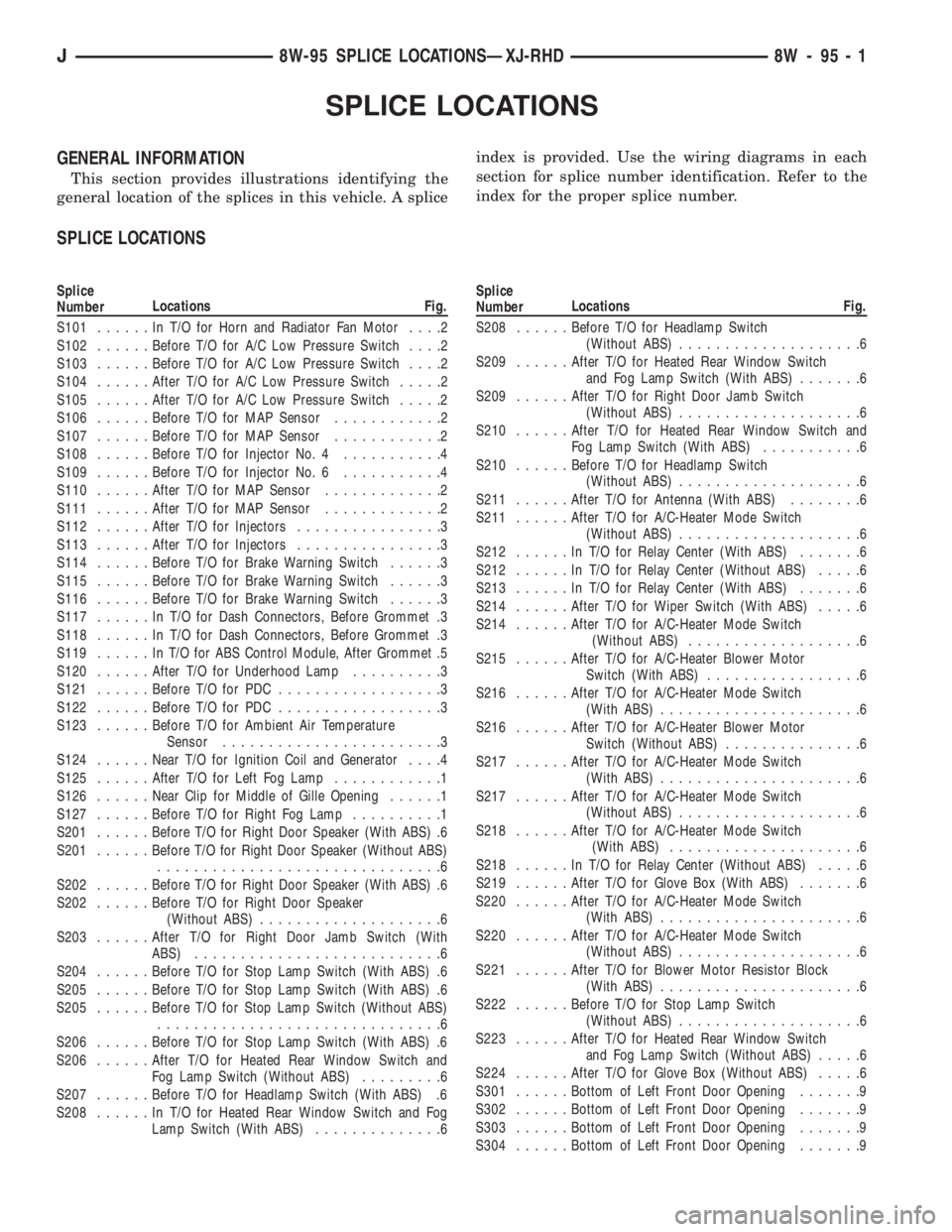
GENERAL INFORMATION
This section provides illustrations identifying the
general location of the splices in this vehicle. A spliceindex is provided. Use the wiring diagrams in each
section for splice number identification. Refer to the
index for the proper splice number.
SPLICE LOCATIONS
Splice
NumberLocations Fig.
S101......InT/OforHorn and Radiator Fan Motor....2
S102......Before T/O for A/C Low Pressure Switch....2
S103......Before T/O for A/C Low Pressure Switch....2
S104......After T/O for A/C Low Pressure Switch.....2
S105......After T/O for A/C Low Pressure Switch.....2
S106......Before T/O for MAP Sensor............2
S107......Before T/O for MAP Sensor............2
S108......Before T/O for Injector No. 4...........4
S109......Before T/O for Injector No. 6...........4
S110......After T/O for MAP Sensor.............2
S111......After T/O for MAP Sensor.............2
S112......After T/O for Injectors................3
S113......After T/O for Injectors................3
S114......Before T/O for Brake Warning Switch......3
S115......Before T/O for Brake Warning Switch......3
S116......Before T/O for Brake Warning Switch......3
S117......InT/OforDash Connectors, Before Grommet .3
S118......InT/OforDash Connectors, Before Grommet .3
S119......InT/OforABSControl Module, After Grommet .5
S120......After T/O for Underhood Lamp..........3
S121......Before T/O for PDC..................3
S122......Before T/O for PDC..................3
S123......Before T/O for Ambient Air Temperature
Sensor........................3
S124......Near T/O for Ignition Coil and Generator....4
S125......After T/O for Left Fog Lamp............1
S126......Near Clip for Middle of Gille Opening......1
S127......Before T/O for Right Fog Lamp..........1
S201......Before T/O for Right Door Speaker (With ABS) .6
S201......Before T/O for Right Door Speaker (Without ABS)
...............................6
S202......Before T/O for Right Door Speaker (With ABS) .6
S202......Before T/O for Right Door Speaker
(Without ABS)....................6
S203......After T/O for Right Door Jamb Switch (With
ABS)...........................6
S204......Before T/O for Stop Lamp Switch (With ABS) .6
S205......Before T/O for Stop Lamp Switch (With ABS) .6
S205......Before T/O for Stop Lamp Switch (Without ABS)
...............................6
S206......Before T/O for Stop Lamp Switch (With ABS) .6
S206......After T/O for Heated Rear Window Switch and
Fog Lamp Switch (Without ABS).........6
S207......Before T/O for Headlamp Switch (With ABS) .6
S208......InT/OforHeated Rear Window Switch and Fog
Lamp Switch (With ABS)..............6Splice
NumberLocations Fig.
S208......Before T/O for Headlamp Switch
(Without ABS)....................6
S209......After T/O for Heated Rear Window Switch
and Fog Lamp Switch (With ABS).......6
S209......After T/O for Right Door Jamb Switch
(Without ABS)....................6
S210......After T/O for Heated Rear Window Switch and
Fog Lamp Switch (With ABS)...........6
S210......Before T/O for Headlamp Switch
(Without ABS)....................6
S211......After T/O for Antenna (With ABS)........6
S211......After T/O for A/C-Heater Mode Switch
(Without ABS)....................6
S212......InT/OforRelay Center (With ABS).......6
S212......InT/OforRelay Center (Without ABS).....6
S213......InT/OforRelay Center (With ABS).......6
S214......After T/O for Wiper Switch (With ABS).....6
S214......After T/O for A/C-Heater Mode Switch
(Without ABS)...................6
S215......After T/O for A/C-Heater Blower Motor
Switch (With ABS).................6
S216......After T/O for A/C-Heater Mode Switch
(With ABS)......................6
S216......After T/O for A/C-Heater Blower Motor
Switch (Without ABS)...............6
S217......After T/O for A/C-Heater Mode Switch
(With ABS)......................6
S217......After T/O for A/C-Heater Mode Switch
(Without ABS)....................6
S218......After T/O for A/C-Heater Mode Switch
(With ABS).....................6
S218......InT/OforRelay Center (Without ABS).....6
S219......After T/O for Glove Box (With ABS).......6
S220......After T/O for A/C-Heater Mode Switch
(With ABS)......................6
S220......After T/O for A/C-Heater Mode Switch
(Without ABS)....................6
S221......After T/O for Blower Motor Resistor Block
(With ABS)......................6
S222......Before T/O for Stop Lamp Switch
(Without ABS)....................6
S223......After T/O for Heated Rear Window Switch
and Fog Lamp Switch (Without ABS).....6
S224......After T/O for Glove Box (Without ABS).....6
S301......Bottom of Left Front Door Opening.......9
S302......Bottom of Left Front Door Opening.......9
S303......Bottom of Left Front Door Opening.......9
S304......Bottom of Left Front Door Opening.......9
J8W-95 SPLICE LOCATIONSÐXJ-RHD 8W - 95 - 1
Page 1122 of 2158
FUEL/IGNITION
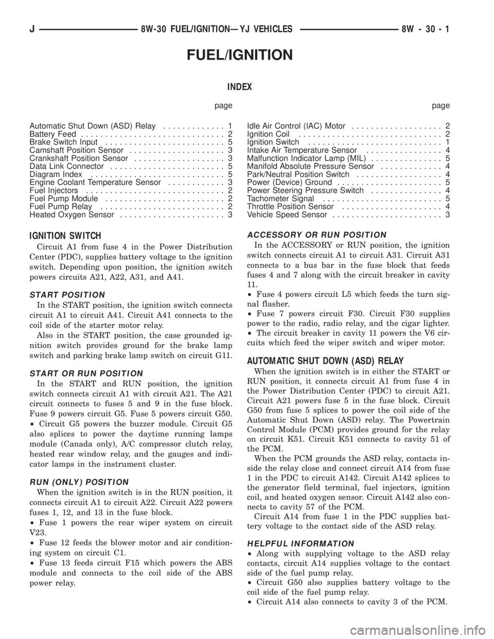
INDEX
page page
Automatic Shut Down (ASD) Relay............. 1
Battery Feed.............................. 2
Brake Switch Input......................... 5
Camshaft Position Sensor.................... 3
Crankshaft Position Sensor................... 3
Data Link Connector........................ 5
Diagram Index............................ 5
Engine Coolant Temperature Sensor............ 3
Fuel Injectors............................. 2
Fuel Pump Module......................... 2
Fuel Pump Relay.......................... 2
Heated Oxygen Sensor...................... 3Idle Air Control (IAC) Motor................... 2
Ignition Coil.............................. 2
Ignition Switch............................ 1
Intake Air Temperature Sensor................ 4
Malfunction Indicator Lamp (MIL)............... 5
Manifold Absolute Pressure Sensor............. 4
Park/Neutral Position Switch.................. 4
Power (Device) Ground...................... 5
Power Steering Pressure Switch............... 4
Tachometer Signal......................... 5
Throttle Position Sensor..................... 4
Vehicle Speed Sensor....................... 3
IGNITION SWITCH
Circuit A1 from fuse 4 in the Power Distribution
Center (PDC), supplies battery voltage to the ignition
switch. Depending upon position, the ignition switch
powers circuits A21, A22, A31, and A41.
START POSITION
In the START position, the ignition switch connects
circuit A1 to circuit A41. Circuit A41 connects to the
coil side of the starter motor relay.
Also in the START position, the case grounded ig-
nition switch provides ground for the brake lamp
switch and parking brake lamp switch on circuit G11.
START OR RUN POSITION
In the START and RUN position, the ignition
switch connects circuit A1 with circuit A21. The A21
circuit connects to fuses 5 and 9 in the fuse block.
Fuse 9 powers circuit G5. Fuse 5 powers circuit G50.
²Circuit G5 powers the buzzer module. Circuit G5
also splices to power the daytime running lamps
module (Canada only), A/C compressor clutch relay,
heated rear window relay, and the gauges and indi-
cator lamps in the instrument cluster.
RUN (ONLY) POSITION
When the ignition switch is in the RUN position, it
connects circuit A1 to circuit A22. Circuit A22 powers
fuses 1, 12, and 13 in the fuse block.
²Fuse 1 powers the rear wiper system on circuit
V23.
²Fuse 12 feeds the blower motor and air condition-
ing system on circuit C1.
²Fuse 13 feeds circuit F15 which powers the ABS
module and connects to the coil side of the ABS
power relay.
ACCESSORY OR RUN POSITION
In the ACCESSORY or RUN position, the ignition
switch connects circuit A1 to circuit A31. Circuit A31
connects to a bus bar in the fuse block that feeds
fuses 4 and 7 along with the circuit breaker in cavity
11 .
²Fuse 4 powers circuit L5 which feeds the turn sig-
nal flasher.
²Fuse 7 powers circuit F30. Circuit F30 supplies
power to the radio, radio relay, and the cigar lighter.
²The circuit breaker in cavity 11 powers the V6 cir-
cuits which feed the wiper switch and wiper motor.
AUTOMATIC SHUT DOWN (ASD) RELAY
When the ignition switch is in either the START or
RUN position, it connects circuit A1 from fuse 4 in
the Power Distribution Center (PDC) to circuit A21.
Circuit A21 powers fuse 5 in the fuse block. Circuit
G50 from fuse 5 splices to power the coil side of the
Automatic Shut Down (ASD) relay. The Powertrain
Control Module (PCM) provides ground for the relay
on circuit K51. Circuit K51 connects to cavity 51 of
the PCM.
When the PCM grounds the ASD relay, contacts in-
side the relay close and connect circuit A14 from fuse
1 in the PDC to circuit A142. Circuit A142 splices to
the generator field terminal, fuel injectors, ignition
coil, and heated oxygen sensor. Circuit A142 also con-
nects to cavity 57 of the PCM.
Circuit A14 from fuse 1 in the PDC supplies bat-
tery voltage to the contact side of the ASD relay.
HELPFUL INFORMATION
²Along with supplying voltage to the ASD relay
contacts, circuit A14 supplies voltage to the contact
side of the fuel pump relay.
²Circuit G50 also supplies battery voltage to the
coil side of the fuel pump relay.
²Circuit A14 also connects to cavity 3 of the PCM.
J8W-30 FUEL/IGNITIONÐYJ VEHICLES 8W - 30 - 1
Page 1168 of 2158
AIR CONDITIONING/HEATER
CONTENTS
page page
HEATER AND AIR CONDITIONING........... 2 HEATERSYSTEM......................... 1
GENERAL INFORMATION
This section of the wiring diagrams is divided into
two sub-sections; Heater, and A/C-Heater. When re-
ferring to the circuit descriptions or wiring diagrams,
ensure that you use the correct sub-section.
HEATER SYSTEM
HEATER
In the RUN position, the ignition switch connects
circuit A1 from fuse 4 in the Power Distribution Cen-
ter (PDC) to circuit A22. Circuit A22 powers a bus
bar in the fuse block that supplies voltage to circuit
C1 through fuse 12.
A heater-off switch in circuit C1 opens when the
heater controls are in the VENT position. When the
heater-off switch closes, circuit C1 supplies battery
voltage to the blower motor switch. The switch sets
blower motor speed to HIGH, MEDIUM, LOW or
OFF.
The switch connects to the blower motor resistor
block in the LOW and MEDIUM positions and di-
rectly to the blower motor in the HIGH position. The
resistor block contains two resistors connected in se-
ries. Circuit C7 connects the resistor block to the
blower motor.
From the blower motor resistor block, circuit C7 is
double crimped at the HIGH terminal of the blower
motor switch. Circuit C7 continues to the blower mo-
tor from the blower motor switch.
When the blower motor switch is in the LOW posi-
tion, it supplies voltage to the resistor block on cir-
cuit C4. From circuit C4, voltage passes through both
resistors in the resistor block to the blower motor on
circuit C7.In the MEDIUM position, the blower motor sup-
plies voltage to the resistor block on circuit C5. From
circuit C5 voltage flows through one resistor to the
blower motor on circuit C7.
In the HIGH position, the blower motor switch con-
nects directly to the blower motor on circuit C7. Volt-
age does not pass through the resistor block.
Circuit Z1 provides ground for the blower motor.
HELPFUL INFORMATION
²Check fuse 4 in the PDC.
²Check fuse 12 in the fuse block.
DIAGRAM INDEX
Component Page
Blower Motor...........................8W-42-3
Blower Motor Resistor.....................8W-42-3
Blower Motor Switch......................8W-42-3
Fuse 4 (PDC)...........................8W-42-3
Fuse 12 (Fuse Block)......................8W-42-3
Heater Switch...........................8W-42-3
Ignition Switch..........................8W-42-3
J8W-42 AIR CONDITIONING/HEATERÐYJ VEHICLES 8W - 42 - 1
Page 1169 of 2158

AIR CONDITIONING AND HEATER
GENERAL INFORMATION
On vehicles built with the 2.5L engine, the electri-
cal system has provisions for dealer installed air con-
ditioning. The provisions consist of two connectors
which include circuitry for:
²Circuit C1 - Ignition feed
²Circuit C21 - Blower motor switch
²Circuit C91 - A/C request signal
²Circuit C20 - A/C select signal
²Circuit C13 - Ground for coil side of A/C compres-
sor clutch relay
²Circuit G5 - Battery voltage for coil side of A/C
compressor clutch relay
A/C COMPRESSOR
When the ignition switch is in the RUN position it
connects circuit A1 from fuse 4 in the Power Distri-
bution Center (PDC) to circuit A22. Circuit A22 sup-
plies battery voltage to fuse 12 in the fuse block.
Fuse 12 powers circuit C1.
Circuit C1 supplies battery voltage to the A/C
blower switch. Circuit C21 connects the A/C blower
switch to the A/C low pressure switch.
When the operator selects A/C operation, the A/C
blower switch provides the A/C request signal to cav-
ity 27 of the Powertrain Control Module (PCM) on
circuit C91. At the same time, the blower switch sup-
plies voltage through the A/C thermostat to circuit
C21.
Circuit C21 supplies voltage to the A/C low pres-
sure switch. When the A/C low pressure switch
closes, circuit C20 provides battery voltage to the
contact side of the A/C compressor clutch relay and
provides the A/C select signal to the PCM. Circuit
C20 is double crimped at the contact side of the re-
lay. The C20 circuit branch from the relay supplies
the A/C select input to cavity 28 of the PCM.
After receiving the A/C request signal, the PCM en-
ergizes the A/C compressor clutch relay by providing
ground for the coil side of the relay on circuit C13.
Circuit C13 connects to cavity 34 of the PCM.
Circuit G5 from fuse 9 in the fuse block supplies
voltage to the coil side of the relay. In the START or
RUN positions the ignition switch connects circuit A1
from fuse 4 in the PDC with circuit A21. Circuit A21
connects to the fuse block bus bar that powers circuit
C5 through fuse 9.
When the PCM energizes the A/C compressor
clutch relay, the relay switches from its normally
grounded position to connect circuit C20 to circuit
C3. Circuit C3 supplies voltage to the case grounded
A/C compressor clutch.
HELPFUL INFORMATION
²Circuit G5 is double crimped at the coil side of the
A/C compressor clutch relay. The G5 branch from the
relay continues to the back-up lamp switch.
²Circuit Z1 provides ground for the A/C compressor
clutch relay when the relay is in its normally
grounded position.
A/C-HEATER BLOWER MOTOR
When the ignition switch is in the RUN position it
connects circuit A1 from fuse 4 in the Power Distri-
bution Center (PDC) to circuit A22. Circuit A22 sup-
plies battery voltage to fuse 12 in the fuse block.
Fuse 12 powers circuit C1.
Circuit C1 supplies battery voltage to the A/C
blower switch. In the LOW position, the A/C blower
switch supplies voltage to the low speed brush of the
blower motor. In the MEDIUM position, the switch
supplies voltage to the medium speed bush of the
blower motor. In the HIGH position, the switch sup-
plies voltage to the high speed brush of the blower
motor.
The blower motor has a field jumper. The ground
circuit for the blower motor connects to the cigar
lighter. Circuit Z1 provides ground for the blower mo-
tor and the cigar lighter.
HELPFUL INFORMATION
²Check fuse 4 in the PDC.
²Check fuse 12 in the fuse block.
DIAGRAM INDEX
Component Page
A/C Compressor Clutch.....................8W-42-4
A/C Compressor Clutch Relay................8W-42-4
A/C Thermostat..........................8W-42-5
Blower Motor...........................8W-42-5
Blower Motor Switch......................8W-42-5
Fuse 4 (PDC).........................8W-42-4, 6
Fuse 7 (Fuse Block).......................8W-42-6
Fuse 9 (Fuse Block).....................8W-42-4, 6
Fuse 12 (Fuse Block)....................8W-42-4, 6
Ignition Switch........................8W-42-4, 6
Powertrain Control Module.................8W-42-4, 6
8W - 42 - 2 8W-42 AIR CONDITIONING/HEATERÐYJ VEHICLESJ
Page 2083 of 2158
HEATERÐYJ
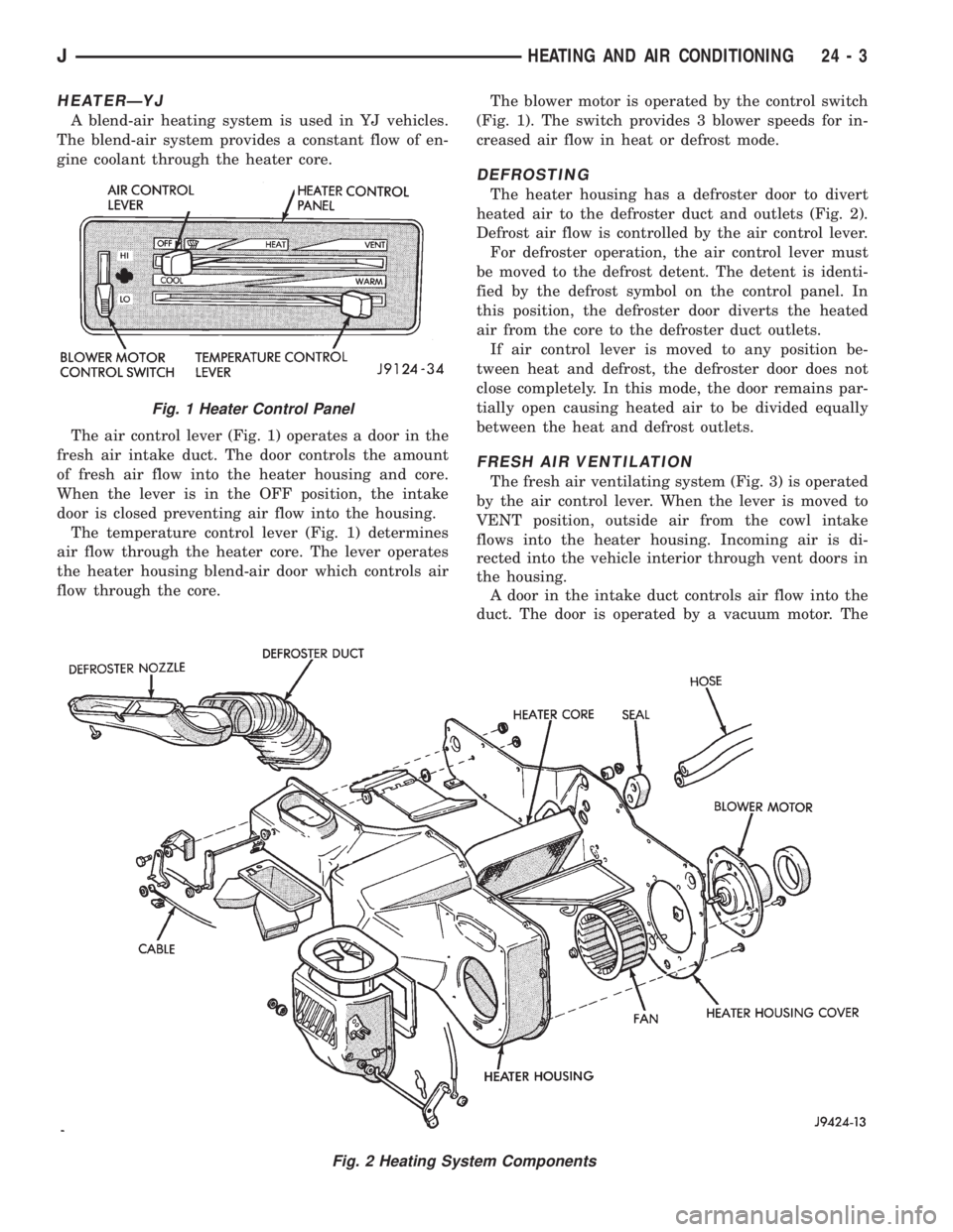
A blend-air heating system is used in YJ vehicles.
The blend-air system provides a constant flow of en-
gine coolant through the heater core.
The air control lever (Fig. 1) operates a door in the
fresh air intake duct. The door controls the amount
of fresh air flow into the heater housing and core.
When the lever is in the OFF position, the intake
door is closed preventing air flow into the housing.
The temperature control lever (Fig. 1) determines
air flow through the heater core. The lever operates
the heater housing blend-air door which controls air
flow through the core.The blower motor is operated by the control switch
(Fig. 1). The switch provides 3 blower speeds for in-
creased air flow in heat or defrost mode.
DEFROSTING
The heater housing has a defroster door to divert
heated air to the defroster duct and outlets (Fig. 2).
Defrost air flow is controlled by the air control lever.
For defroster operation, the air control lever must
be moved to the defrost detent. The detent is identi-
fied by the defrost symbol on the control panel. In
this position, the defroster door diverts the heated
air from the core to the defroster duct outlets.
If air control lever is moved to any position be-
tween heat and defrost, the defroster door does not
close completely. In this mode, the door remains par-
tially open causing heated air to be divided equally
between the heat and defrost outlets.
FRESH AIR VENTILATION
The fresh air ventilating system (Fig. 3) is operated
by the air control lever. When the lever is moved to
VENT position, outside air from the cowl intake
flows into the heater housing. Incoming air is di-
rected into the vehicle interior through vent doors in
the housing.
A door in the intake duct controls air flow into the
duct. The door is operated by a vacuum motor. The
Fig. 2 Heating System Components
Fig. 1 Heater Control Panel
JHEATING AND AIR CONDITIONING 24 - 3
Page 2095 of 2158
HEATING AND AIR CONDITIONING TEST PROCEDURES
INDEX
page page
A/C Compressor Clutch..................... 15
A/C Compressor Clutch Relay................ 15
A/C Compressor Clutch Relay................ 16
Air Conditioning ControlsÐXJ Vehicles......... 15
Air Conditioning ControlsÐYJ Vehicles......... 16
Blower Motor............................ 17
Blower Motor Switch....................... 16Compressor Clutch........................ 16
Fin Sensing Cycling Clutch Switch............. 15
Heater Diagnosis......................... 17
Low-Pressure High-Pressure Cut-Off Switch..... 15
Low-Pressure High-Pressure Cut-Off Switch..... 16
Thermostatic Control....................... 16
AIR CONDITIONING CONTROLSÐXJ VEHICLES
The A/C Compressor Clutch is controlled by several
components: the Pressure Cut-Off Switch, Cycling
Clutch Switch, Clutch Relay and Powertrain Control
Module (PCM).
Powertrain Control Module may delay A/C clutch
engagement up to 30 seconds.
Refer to Group 8W Wiring Diagrams for wiring and
terminals. Use volt ohmmeter to test switches.
A/C COMPRESSOR CLUTCH
The clutch assembly consists of a stationary elec-
tromagnetic coil, hub bearing pulley assembly, and
clutch plate. When the coil is energized the plate is
magnetically engaged with the pulley and turns the
compressor shaft.
A/C COMPRESSOR CLUTCH TEST
(1) Unplug clutch coil connector.
(2) Connect a jumper wire from the battery posi-
tive post to the clutch coil terminal. The clutch
should engage, if not leave jumper wire connected
and go to next step.
(3) Connect a jumper wire from clutch coil frame to
chassis ground. The clutch should engage if not re-
pair clutch coil ground or replace coil.
A/C COMPRESSOR CLUTCH RELAY
The A/C compressor clutch relay controls the 12-
volt source to the A/C clutch. The relay is activated
when the PCM receives a A/C request signal from the
fin-sensed cycling clutch switch. The PCM then sends
a ground signal to the relay. The relay is activated
and sends 12-volts to the clutch coil which energizes
the clutch. The relay is located in the power distribu-
tion center.
COMPRESSOR CLUTCH RELAY TEST
For test procedure refer to Powertrain Diagnostic
Service Manual for A/C clutch relay circuit test.
LOW-PRESSURE HIGH-PRESSURE CUT-OFF
SWITCH
The pressure cut-off switch is located on the filter
drier and is wired in series with compressor clutch.
The switch interrupts the power to the compressor
clutch circuit when the pressure drops to 193 kPa (28
psi) or increases above 3100 to 3375 kPa (450 to 490
psi).
PRESSURE CUT-OFF SWITCH TEST
(1) Verify system has correct refrigerant charge.
(2) Turn ignition switch to RUN, A/C blower switch
to ON and control set to MAX.
(3) Unplug pressure cut-off switch and test feed
circuit from select switch. It should be battery volt-
age if not, repair open to select switch.
(4) Test for continuity between the switch termi-
nals. If continuity is not present recover refrigerant
from the system. Replace switch, evacuate and re-
charge system.
FIN SENSING CYCLING CLUTCH SWITCH
The switch is attached to the evaporator coil with
the temperature sensing probe inserted into the coil
fins. This switch prevents condensate water on the
evaporator coil from freezing. It does this by sending
signals to the PCM to cycling the compressor clutch
on and off.
FIN-SENSED CYCLING CLUTCH SWITCH TEST
Test area ambient temperature should be around
21ÉC (70ÉF) for test.
(1) Verify system has correct refrigerant charge.
(2) Start Engine and turn on A/C.
(3) If the compressor clutch cycles ON and OFF 2
to 3 times per minute the cycling clutch switch is
normal. The ambient temperature should be between
20ÉC-30ÉC (68ÉF-90ÉF). Above 32ÉC (90ÉF) the com-
pressor clutch may stay engaged (non cycling) due to
the high heat load, this condition is normal. If the
compressor clutch fails to engage go to next step.
(4) Disconnect wiring harness connector from
switch. With a volt meter test feed circuit from cut-
JHEATING AND AIR CONDITIONING 24 - 15