1995 JEEP YJ transmission fluid
[x] Cancel search: transmission fluidPage 266 of 2158

WARNING: CONSTANT TENSION HOSE CLAMPS
ARE USED ON MOST COOLING SYSTEM HOSES.
WHEN REMOVING OR INSTALLING, USE ONLY
TOOLS DESIGNED FOR SERVICING THIS TYPE OF
CLAMP, SUCH AS SPECIAL CLAMP TOOL (NUMBER
6094) (FIG. 27). SNAP-ON CLAMP TOOL (NUMBER
HPC-20) MAY BE USED FOR LARGER CLAMPS. AL-
WAYS WEAR SAFETY GLASSES WHEN SERVICING
CONSTANT TENSION CLAMPS.
CAUTION: A number or letter is stamped into the
tongue of constant tension clamps (Fig. 28). If re-
placement is necessary, use only an original equip-
ment clamp with matching number or letter.XJ MODELS WITH 2.5L 4-CYLINDER ENGINE
REMOVAL
(1) Disconnect negative battery cable at battery.
(2) Observe the previousWARNINGS.Remove ra-
diator cap.
(3) Position drain pan under draincock. Open radi-
ator draincock. Drain radiator.
(4) Remove radiator upper and lower hose clamps
(Figs. 27 and 28). Remove hoses.
(5) Remove E-clip from alignment dowel at radia-
tor lower mounting bracket (Fig. 29).
(6) Disconnect coolant reserve/overflow tank hose
from radiator.
(7) Remove four radiator fan shroud mounting
bolts (Fig. 29). Push shroud back against front of en-
gine.
(8) If equipped, disconnect and plug automatic
transmission fluid cooler lines. Refer to Group 21,
Transmission for procedures.
(9) Remove two radiator top mounting bolts (Fig.
29).
(10) (a) If equipped with air conditioning, remove
the radiator grille mounting screws and remove grill.
Refer to Group 23, Body for procedures.
(b) If equipped, remove the air conditioning con-
denser-to-radiator mounting bolt. Use an open end
wrench to remove bottom bolts (Fig. 30).
(11) Lift radiator straight up and out of vehicle.
Take care not to damage radiator fins. When remov-
ing radiator, note position of the rubber seals located
on the top, bottom and sides of radiator (Fig. 29). To
prevent possible overheating, these seals must be in-
stalled to their original positions.
INSTALLATION
(1) Install radiator behind air conditioning con-
denser with bottom alignment dowel inserted into ra-
diator lower mounting bracket (Fig. 29).
(2) Install E-clip to radiator alignment dowel (Fig.
29).
(3) Tighten the four condenser-to-radiator mount-
ing bolts to 6.2 Nzm (55 in. lbs.) torque.
(4) If removed, install radiator grille.
(5) Tighten radiator top mounting bolts to 6 Nzm
(55 in. lbs.) torque.
(6) If equipped, connect automatic transmission
fluid cooler lines to radiator. Refer to Group 21,
Transmission for procedures.
(7) Install the radiator fan shroud.
(8) Connect the coolant reserve/overflow tank hose.
(9) Connect radiator hoses and install hose clamps.
(10) Connect negative battery cable.
(11) Close the draincock.
(12) Fill cooling system with correct coolant.
(13) Install radiator cap.
(14) Check and adjust automatic transmission
fluid level (if equipped).
Fig. 27 Hose Clamp ToolÐTypical
Fig. 28 Clamp Number/Letter Location
JCOOLING SYSTEM SERVICE PROCEDURES 7 - 27
Page 268 of 2158

(4) For access to radiator draincock, remove radia-
tor grille mounting screws and remove grill. Refer to
Group 23, Body for procedures.
(5) Attach one end of a 24 inch long X 1/4 inch ID
hose to the radiator draincock. Put the other end into
a clean container. Open draincock and drain radiator.
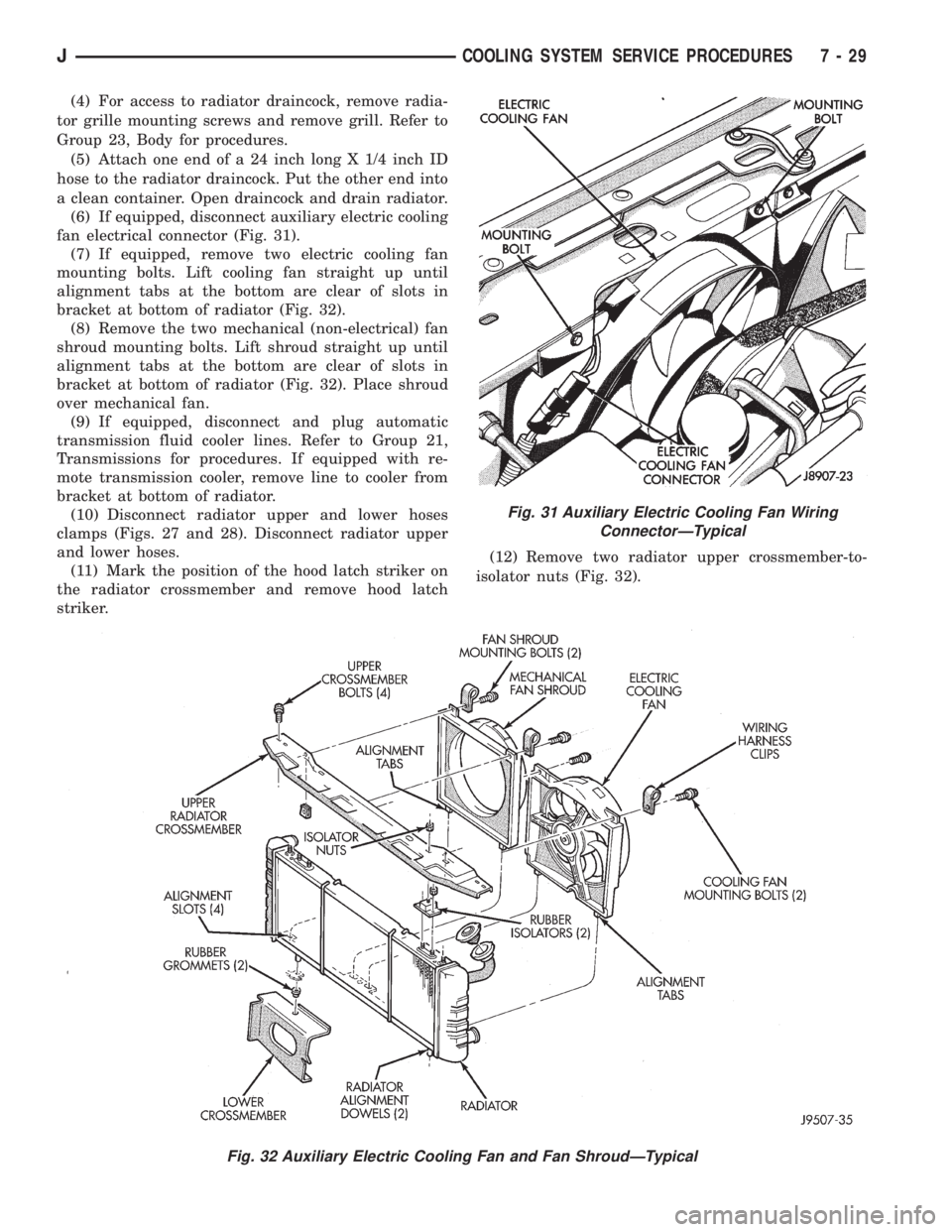
(6) If equipped, disconnect auxiliary electric cooling
fan electrical connector (Fig. 31).
(7) If equipped, remove two electric cooling fan
mounting bolts. Lift cooling fan straight up until
alignment tabs at the bottom are clear of slots in
bracket at bottom of radiator (Fig. 32).
(8) Remove the two mechanical (non-electrical) fan
shroud mounting bolts. Lift shroud straight up until
alignment tabs at the bottom are clear of slots in
bracket at bottom of radiator (Fig. 32). Place shroud
over mechanical fan.
(9) If equipped, disconnect and plug automatic
transmission fluid cooler lines. Refer to Group 21,
Transmissions for procedures. If equipped with re-
mote transmission cooler, remove line to cooler from
bracket at bottom of radiator.
(10) Disconnect radiator upper and lower hoses
clamps (Figs. 27 and 28). Disconnect radiator upper
and lower hoses.
(11) Mark the position of the hood latch striker on
the radiator crossmember and remove hood latch
striker.(12) Remove two radiator upper crossmember-to-
isolator nuts (Fig. 32).
Fig. 31 Auxiliary Electric Cooling Fan Wiring
ConnectorÐTypical
Fig. 32 Auxiliary Electric Cooling Fan and Fan ShroudÐTypical
JCOOLING SYSTEM SERVICE PROCEDURES 7 - 29
Page 269 of 2158

(13) Remove four radiator upper crossmember
bolts (Fig. 32) and remove upper crossmember.
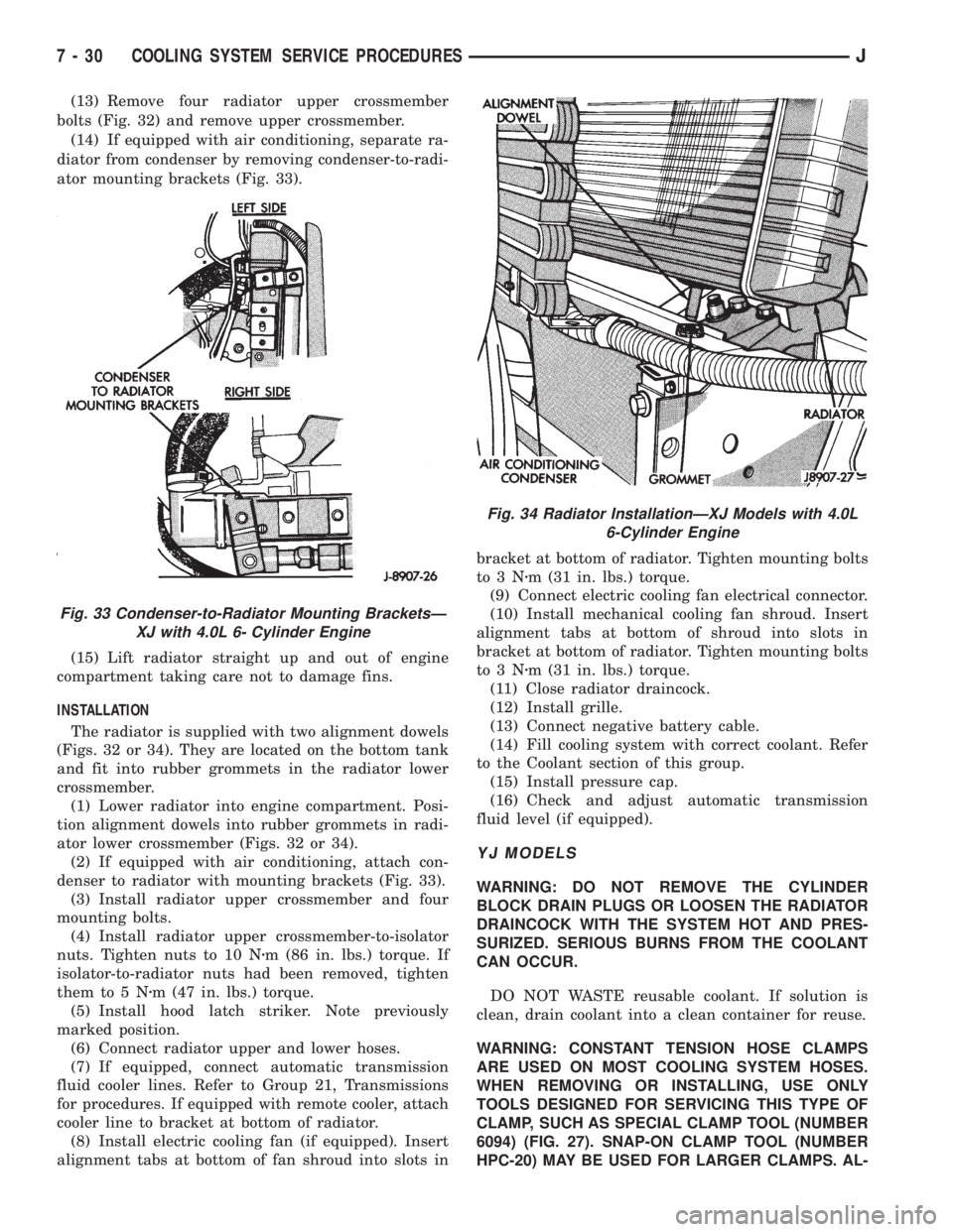
(14) If equipped with air conditioning, separate ra-
diator from condenser by removing condenser-to-radi-
ator mounting brackets (Fig. 33).
(15) Lift radiator straight up and out of engine
compartment taking care not to damage fins.
INSTALLATION
The radiator is supplied with two alignment dowels
(Figs. 32 or 34). They are located on the bottom tank
and fit into rubber grommets in the radiator lower
crossmember.
(1) Lower radiator into engine compartment. Posi-
tion alignment dowels into rubber grommets in radi-
ator lower crossmember (Figs. 32 or 34).
(2) If equipped with air conditioning, attach con-
denser to radiator with mounting brackets (Fig. 33).
(3) Install radiator upper crossmember and four
mounting bolts.
(4) Install radiator upper crossmember-to-isolator
nuts. Tighten nuts to 10 Nzm (86 in. lbs.) torque. If
isolator-to-radiator nuts had been removed, tighten
them to 5 Nzm (47 in. lbs.) torque.
(5) Install hood latch striker. Note previously
marked position.
(6) Connect radiator upper and lower hoses.
(7) If equipped, connect automatic transmission
fluid cooler lines. Refer to Group 21, Transmissions
for procedures. If equipped with remote cooler, attach
cooler line to bracket at bottom of radiator.
(8) Install electric cooling fan (if equipped). Insert
alignment tabs at bottom of fan shroud into slots inbracket at bottom of radiator. Tighten mounting bolts
to3Nzm (31 in. lbs.) torque.
(9) Connect electric cooling fan electrical connector.
(10) Install mechanical cooling fan shroud. Insert
alignment tabs at bottom of shroud into slots in
bracket at bottom of radiator. Tighten mounting bolts
to3Nzm (31 in. lbs.) torque.
(11) Close radiator draincock.
(12) Install grille.
(13) Connect negative battery cable.
(14) Fill cooling system with correct coolant. Refer
to the Coolant section of this group.
(15) Install pressure cap.
(16) Check and adjust automatic transmission
fluid level (if equipped).
YJ MODELS
WARNING: DO NOT REMOVE THE CYLINDER
BLOCK DRAIN PLUGS OR LOOSEN THE RADIATOR
DRAINCOCK WITH THE SYSTEM HOT AND PRES-
SURIZED. SERIOUS BURNS FROM THE COOLANT
CAN OCCUR.
DO NOT WASTE reusable coolant. If solution is
clean, drain coolant into a clean container for reuse.
WARNING: CONSTANT TENSION HOSE CLAMPS
ARE USED ON MOST COOLING SYSTEM HOSES.
WHEN REMOVING OR INSTALLING, USE ONLY
TOOLS DESIGNED FOR SERVICING THIS TYPE OF
CLAMP, SUCH AS SPECIAL CLAMP TOOL (NUMBER
6094) (FIG. 27). SNAP-ON CLAMP TOOL (NUMBER
HPC-20) MAY BE USED FOR LARGER CLAMPS. AL-
Fig. 33 Condenser-to-Radiator Mounting BracketsÐ
XJ with 4.0L 6- Cylinder Engine
Fig. 34 Radiator InstallationÐXJ Models with 4.0L
6-Cylinder Engine
7 - 30 COOLING SYSTEM SERVICE PROCEDURESJ
Page 270 of 2158

WAYS WEAR SAFETY GLASSES WHEN SERVICING
CONSTANT TENSION CLAMPS.
CAUTION: A number or letter is stamped into the
tongue of constant tension clamps (Fig. 28). If re-
placement is necessary, use only an original equip-
ment clamp with matching number or letter.
REMOVAL
(1) Disconnect negative battery cable at battery.
(2) Observe the previousWARNINGS.Remove the
radiator cap.
(3) Position drain pan under draincock. Open radi-
ator draincock and drain radiator.
(4) Remove radiator upper and lower hose clamps
(Figs 27 and 28). Remove radiator hoses.
(5) Disconnect coolant reserve/overflow tank hose
from radiator.
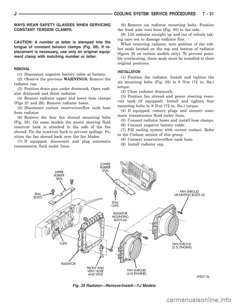
(6) Remove the four fan shroud mounting bolts
(Fig. 35). On some models the power steering fluid
reservoir tank is attached to the side of the fan
shroud. Tie the reservoir back to prevent spillage. Po-
sition the fan shroud back over the fan blades.
(7) If equipped, disconnect and plug automatic
transmission fluid cooler lines.(8) Remove six radiator mounting bolts. Position
the front axle vent hose (Fig. 35) to the side.
(9) Lift radiator straight up and out of vehicle tak-
ing care not to damage radiator fins.
When removing radiator, note position of the rub-
ber seals located on the top and bottom of radiator
(figure 35 on certain models only). To prevent possi-
ble overheating, these seals must be installed to their
original positions.
INSTALLATION
(1) Position the radiator. Install and tighten the
six mounting bolts (Fig. 35) to 8 Nzm (72 in. lbs.)
torque.
(2) Close radiator draincock.
(3) Position fan shroud and power steering reser-
voir tank (if equipped). Install and tighten four
mounting bolts to 8 Nzm (72 in. lbs.) torque.
(4) If equipped, remove plugs and connect auto-
matic transmission fluid cooler lines.
(5) Connect radiator hoses and install hose clamps.
(6) Connect negative battery cable.
(7) Fill cooling system with correct coolant. Refer
to the Coolant section of this group.
(8) Connect reserve/overflow tank hose.
(9) Install radiator cap.
Fig. 35 RadiatorÐRemove/InstallÐYJ Models
JCOOLING SYSTEM SERVICE PROCEDURES 7 - 31
Page 271 of 2158

(10) Check and adjust automatic transmission
fluid level (if equipped).
COOLING SYSTEM HOSES
Rubber hoses route coolant to and from the radia-
tor, intake manifold and heater core. All XJ models
equipped with air conditioning have a coolant control
valve. This is located in-line with the heater core in-
let and outlet hoses. It controls coolant flow to the
heater core when the air conditioning system is in
operation.
Radiator lower hoses are spring-reinforced to pre-
vent collapse from water pump suction at moderate
and high engine speeds.
WARNING: CONSTANT TENSION HOSE CLAMPS
ARE USED ON MOST COOLING SYSTEM HOSES.
WHEN REMOVING OR INSTALLING, USE ONLY
TOOLS DESIGNED FOR SERVICING THIS TYPE OF
CLAMP, SUCH AS SPECIAL CLAMP TOOL (NUMBER
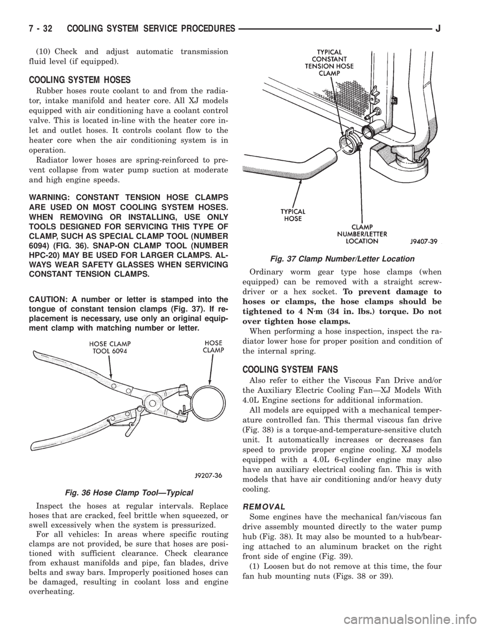
6094) (FIG. 36). SNAP-ON CLAMP TOOL (NUMBER
HPC-20) MAY BE USED FOR LARGER CLAMPS. AL-
WAYS WEAR SAFETY GLASSES WHEN SERVICING
CONSTANT TENSION CLAMPS.
CAUTION: A number or letter is stamped into the
tongue of constant tension clamps (Fig. 37). If re-
placement is necessary, use only an original equip-
ment clamp with matching number or letter.
Inspect the hoses at regular intervals. Replace
hoses that are cracked, feel brittle when squeezed, or
swell excessively when the system is pressurized.
For all vehicles: In areas where specific routing
clamps are not provided, be sure that hoses are posi-
tioned with sufficient clearance. Check clearance
from exhaust manifolds and pipe, fan blades, drive
belts and sway bars. Improperly positioned hoses can
be damaged, resulting in coolant loss and engine
overheating.Ordinary worm gear type hose clamps (when
equipped) can be removed with a straight screw-
driver or a hex socket.To prevent damage to
hoses or clamps, the hose clamps should be
tightened to 4 Nzm (34 in. lbs.) torque. Do not
over tighten hose clamps.
When performing a hose inspection, inspect the ra-
diator lower hose for proper position and condition of
the internal spring.
COOLING SYSTEM FANS
Also refer to either the Viscous Fan Drive and/or
the Auxiliary Electric Cooling FanÐXJ Models With
4.0L Engine sections for additional information.
All models are equipped with a mechanical temper-
ature controlled fan. This thermal viscous fan drive
(Fig. 38) is a torque-and-temperature-sensitive clutch
unit. It automatically increases or decreases fan
speed to provide proper engine cooling. XJ models
equipped with a 4.0L 6-cylinder engine may also
have an auxiliary electrical cooling fan. This is with
models that have air conditioning and/or heavy duty
cooling.
REMOVAL
Some engines have the mechanical fan/viscous fan
drive assembly mounted directly to the water pump
hub (Fig. 38). It may also be mounted to a hub/bear-
ing attached to an aluminum bracket on the right
front side of engine (Fig. 39).
(1) Loosen but do not remove at this time, the four
fan hub mounting nuts (Figs. 38 or 39).
Fig. 36 Hose Clamp ToolÐTypical
Fig. 37 Clamp Number/Letter Location
7 - 32 COOLING SYSTEM SERVICE PROCEDURESJ
Page 275 of 2158

nostic Procedures manual for diagnostic information
and operation of the DRB scan tool.
To test operation of the fan relay only, refer to Re-
laysÐOperation/Testing. This can be found in Group
14, Fuel Systems.
REMOVAL
The auxiliary cooling fan is attached to the radia-
tor upper crossmember behind the radiator.
(1) Remove the two fan mounting bolts from radi-
ator upper crossmember (Fig. 43).
(2) Disconnect the electric fan connector.
(3) Lift fan straight up and out of vehicle.
INSTALLATION
(1) Align lower retaining tabs of fan shroud with
slots in bracket at bottom of radiator. Push fan down
into position.
(2) Tighten the mounting bolts to 4 Nzm (31 in.
lbs.) torque.
(3) Connect auxiliary cooling fan electrical connec-
tor.
TRANSMISSION OIL COOLERS
WATER-TO-OIL COOLER
All models equipped with an automatic transmis-
sion are equipped with a transmission oil cooler
mounted internally within the radiator tank. This in-
ternal cooler is supplied as standard equipment on
all models equipped with an automatic transmission.
Transmission oil is cooled when it passes through
this separate cooler. In case of a leak in the internalradiator mounted transmission oil cooler, engine cool-
ant may become mixed with transmission fluid or
transmission fluid may enter engine cooling system.
Both cooling system and transmission should be
drained and inspected if the internal radiator
mounted transmission cooler is leaking.
Also refer to the section on Transmission Air-to-Oil
Coolers. This auxiliary air-to-oil cooler is an option
on most engine packages.
REPLACING WATER-TO-OIL COOLER IN
RADIATOR SIDE TANK
The internal transmission oil cooler located within
the radiator is not serviceable. If it requires service,
the radiator must be replaced.
Once the repaired or replacement radiator has
been installed, fill the cooling system and inspect for
leaks. Refer to the Refilling Cooling System and Test-
ing Cooling System For Leaks sections in this group.
If the transmission operates properly after repairing
the leak, drain the transmission and remove the
transmission oil pan. Inspect for sludge and/or rust.
Inspect for a dirty or plugged inlet filter. If none of
these conditions are found, the transmission and
torque convertor may not require reconditioning. Re-
fer to Group 21 for automatic transmission servicing.
AIR-TO-OIL COOLER
An auxiliary air-to-oil transmission oil cooler is
available with most engine packages.
On XJ and YJ models, the cooler is located in front
of the radiator or A/C condenser (if equipped) and be-
hind the grill (Figs. 44, 45 or 46). It is mounted to
the front frame crossmember.
Fig. 43 Auxiliary Cooling FanÐRemove/InstallÐ
Typical
Fig. 44 Auxiliary Air-To-Oil CoolerÐYJ Models
7 - 36 COOLING SYSTEM SERVICE PROCEDURESJ
Page 358 of 2158

The high-line cluster includes the following gauges:
²coolant temperature gauge
²fuel gauge
²oil pressure gauge
²speedometer/odometer
²tachometer
²trip odometer
²voltmeter.
The high-line cluster includes provisions for the fol-
lowing indicator lamps:
²anti-lock brake system lamp
²brake warning lamp
²four-wheel drive indicator lamps
²headlamp high beam indicator lamp
²low fuel warning lamp
²low washer fluid warning lamp
²malfunction indicator (Check Engine) lamp
²seat belt reminder lamp
²turn signal indicator lamps
²upshift indicator lamp.
GAUGES
With the ignition switch in the ON or START posi-
tion, voltage is supplied to all gauges through the in-
strument cluster gauge area printed circuit. With the
ignition switch in the OFF position, voltage is not
supplied to the gauges. A gauge pointer may remain
within the gauge scale after the ignition switch is
OFF. However, the gauges do not accurately indicate
any vehicle condition unless the ignition switch is
ON.
All gauges except the odometer are air core mag-
netic units. Two fixed electromagnetic coils are lo-
cated within the gauge. These coils are wrapped at
right angles to each other around a movable perma-
nent magnet. The movable magnet is suspended
within the coils on one end of a shaft. The gauge nee-
dle is attached to the other end of the shaft.
One of the coils has a fixed current flowing through
it to maintain a constant magnetic field strength.
Current flow through the second coil changes, which
causes changes in its magnetic field strength. The
current flowing through the second coil can be
changed by:
²a variable resistor-type sending unit (fuel level,
coolant temperature, or oil pressure)
²changes in electrical system voltage (voltmeter)
²electronic control circuitry (speedometer/odometer,
tachometer).
The gauge needle moves as the movable permanent
magnet aligns itself to the changing magnetic fields
created around it by the electromagnets.
COOLANT TEMPERATURE GAUGE
The coolant temperature gauge gives an indication
of engine coolant temperature. The coolant tempera-
ture sending unit is a thermistor that changes elec-
trical resistance with changes in engine coolanttemperature. High sending unit resistance causes
low coolant temperature readings. Low resistance
causes high coolant temperature readings.
The gauge will read at the high end of the scale
when the ignition switch is turned to the START po-
sition. This is caused by the bulb test circuit wiring
provision. The same wiring is used for the high-line
cluster with a coolant temperature gauge and the
low-line cluster with a coolant temperature warning
lamp. Sending unit resistance values are shown in a
chart in Specifications.
FUEL GAUGE
The fuel gauge gives an indication of the level of
fuel in the fuel tank. The fuel gauge sending unit has
a float attached to a swing-arm in the fuel tank. The
float moves up or down within the fuel tank as fuel
level changes. As the float moves, an electrical con-
tact on the swing-arm wipes across a resistor coil,
which changes sending unit resistance. High sending
unit resistance causes low fuel level readings. Low
resistance causes high fuel level readings. Sending
unit resistance values are shown in a chart in Spec-
ifications.
OIL PRESSURE GAUGE
The oil pressure gauge gives an indication of en-
gine oil pressure. The combination oil pressure send-
ing unit contains a flexible diaphragm. The
diaphragm moves in response to changes in engine
oil pressure. As the diaphragm moves, sending unit
resistance increases or decreases. High resistance on
the gauge side of the sending unit causes high oil
pressure readings. Low resistance causes low oil
pressure readings. Sending unit resistance values are
shown in a chart in Specifications.
SPEEDOMETER/ODOMETER
The speedometer/odometer gives an indication of
vehicle speed and travel distance. The speedometer
receives a vehicle speed pulse signal from the Vehicle
Speed Sensor (VSS). An electronic integrated circuit
contained within the speedometer reads and analyzes
the pulse signal. It then adjusts the ground path re-
sistance of one electromagnet in the gauge to control
needle movement. It also sends signals to an electric
stepper motor to control movement of the odometer
number rolls. Frequency values for the pulse signal
are shown in a chart in Specifications.
The VSS is mounted to an adapter near the trans-
mission (two-wheel drive) or transfer case (four-wheel
drive) output shaft. The sensor is driven through the
adapter by a speedometer pinion gear. The adapter
and pinion vary with transmission, transfer case,
axle ratio and tire size. Refer to Group 21 - Trans-
mission and Transfer Case for more information.
8E - 2 INSTRUMENT PANEL AND GAUGESÐXJJ
Page 360 of 2158

HEADLAMP HIGH BEAM INDICATOR LAMP
The high beam indicator lamp is controlled by the
headlamp dimmer (multi-function) switch. One side
of the indicator bulb is grounded at all times. The
other side of the bulb receives battery feed through
the contacts of the dimmer switch when the multi-
function switch stalk is actuated to turn the head-
lamp high beams on. Refer to Group 8L - Lamps for
more information.
LOW FUEL WARNING LAMP
A Light-Emitting Diode (LED) on the face of the
fuel gauge will light when the fuel level falls below
approximately 4 gallons. A low fuel warning module
attached to the rear of the fuel gauge controls when
the LED will light. When the module senses 66.5
ohms or more resistance from the fuel level sending
unit for 10 continuous seconds, the LED will light.
When the module senses 63.5 ohms or less resistance
from the fuel level sending unit for 20 continuous
seconds, the LED is turned off.
LOW OIL PRESSURE WARNING LAMP
The low oil pressure warning lamp lights with the
ignition switch in the ON position and the engine not
running. The lamp should be off when the engine is
running. Battery voltage is supplied to one side of
the indicator bulb when the ignition switch is turned
ON. The warning lamp side of the combination oil
pressure sending unit is connected to the other side
of the bulb. When normal engine oil pressure is ap-
plied to the sending unit, resistance on the warning
lamp side is high and the lamp goes off. When engine
oil pressure is too low, resistance on the warning
lamp side of the sending unit is low, which causes
the bulb to light.
LOW WASHER FLUID WARNING LAMP
The low washer fluid warning lamp indicates when
the fluid level in the washer reservoir is too low. The
washer fluid level sensor uses a float in the reservoir
to monitor fluid level. The action of the float opens or
closes the switch within the sensor that provides ig-
nition-switched battery voltage to the lamp bulb. Re-
fer to Group 8K - Wiper and Washer Systems for
more information.
MALFUNCTION INDICATOR LAMP
The CHECK ENGINE or Malfunction Indicator
Lamp (MIL) lights each time the ignition switch is
turned ON, and stays on for 3 seconds as a bulb test.
If the Powertrain Control Module (PCM) receives an
incorrect signal or no signal from certain fuel oremission system related circuits or components, the
lamp is turned on. This will indicate that the PCM
has recorded a Diagnostic Trouble Code (DTC) in
electronic memory for a circuit or component mal-
function. Refer to Group 14 - Fuel System for more
information.
SEAT BELT REMINDER LAMP
The seat belt reminder lamp lights for 4 to 8 sec-
onds after the ignition switch is turned to the ON po-
sition. A timer in the chime/buzzer module controls
ignition-switched battery feed to the lamp. Refer to
Group 8U - Chime/Buzzer Warning Systems for more
information.
TURN SIGNAL INDICATOR LAMPS
The left and right turn signal indicator lamps are
controlled by the turn signal and hazard warning
(multi-function) switches. One side of the bulb for
each lamp is grounded at all times. The other side of
the bulb receives battery feed through the contacts of
the multi-function switch when the turn signal lever
(multi-function switch stalk) or hazard warning but-
ton are actuated. Refer to Group 8J - Turn Signal
and Hazard Warning Systems for more information.
UPSHIFT INDICATOR LAMP
Vehicles equipped with manual transmissions have
an optional upshift indicator lamp. Ground feed for
the lamp is switched by the Powertrain Control Mod-
ule (PCM). The lamp lights to indicate when the
driver should shift to the next highest gear for best
fuel economy. The PCM will turn the lamp off after 3
to 5 seconds if the upshift is not performed. The lamp
will remain off until the vehicle stops accelerating
and is brought back to the range of lamp operation,
or until the transmission is shifted into another gear.
The indicator lamp is normally on when the igni-
tion switch is turned ON and is turned off when the
engine is started. The lamp will be turned on during
vehicle operation according to engine speed and load.
CLUSTER ILLUMINATION LAMPS
All cluster illumination lamps receive battery feed
from the instrument lamps fuse in the fuseblock
module through the panel dimmer rheostat of the
headlamp switch. When the park or headlamps are
on, the cluster illumination lamps light. Illumination
brightness can be adjusted by rotating the headlamp
switch knob (clockwise to dim, counterclockwise to
brighten).
8E - 4 INSTRUMENT PANEL AND GAUGESÐXJJ