1995 JEEP YJ gas type
[x] Cancel search: gas typePage 1403 of 2158
FUEL SYSTEM
CONTENTS
page page
ACCELERATOR PEDAL AND THROTTLE CABLE.17
FUEL DELIVERY SYSTEM.................. 3
FUEL TANKS........................... 13
GENERAL INFORMATION.................. 1
MULTI-PORT FUEL INJECTION (MFI)Ð
COMPONENT DESCRIPTION/SYSTEMOPERATION.......................... 19
MULTI-PORT FUEL INJECTION (MFI)Ð
COMPONENT REMOVAL/INSTALLATION.... 58
MULTI-PORT FUEL INJECTION (MFI)Ð
GENERAL DIAGNOSIS.................. 35
SPECIFICATIONS........................ 67
GENERAL INFORMATION
Throughout this group, references are made to par-
ticular vehicle models by alphabetical designation
(XJ or YJ) or by the particular vehicle nameplate. A
chart showing a breakdown of the alphabetical desig-
nations is included in the Introduction section at the
beginning of this manual.
TheFuel Systemconsists of: the fuel tank, an
electric (fuel tank mounted) fuel pump and a fuel fil-
ter. It also consists of fuel tubes/lines/hoses, vacuum
hoses, throttle body and fuel injectors.
TheFuel Delivery Systemconsists of: the electric
fuel pump, fuel filter, fuel tubes/lines/hoses, fuel rail,
fuel injectors and fuel pressure regulator.
AFuel Return Systemis used on all vehicles.
The system consists of: the fuel tubes/lines/hoses that
route fuel back to the fuel tank.
TheFuel Tank Assemblyconsists of: the fuel
tank, filler tube, fuel fill and vent hoses, fuel gauge
sending unit/electric fuel pump module, a pressure
relief/rollover valve and a pressure-vacuum filler cap.
Also to be considered part of the fuel system is the
Evaporation Control System.This is designed to
reduce the emission of fuel vapors into the atmo-
sphere. The description and function of the Evapora-
tive Control System is found in Group 25, Emission
Control Systems.
FUEL USAGE STATEMENT
Your vehicle was designed to meet all emission reg-
ulations and provide excellent fuel economy using
high quality unleaded gasoline. Only use unleaded
gasolines having a minimum posted octane of 87.
If your vehicle develops occasional light spark
knock (ping) at low engine speeds, this is not harm-
ful. However,continued heavy knock at high
speeds can cause damage and should be re-
ported to your dealer immediately.Engine dam-
age as a result of heavy knock operation may not becovered by the new vehicle warranty.
In addition to using unleaded gasoline with the
proper octane rating,those that contain deter-
gents, corrosion and stability additives are rec-
ommended.Using gasolines that have these
additives will help improve fuel economy, reduce
emissions and maintain vehicle performance.
Poor quality gasolinecan cause problems such
as hard starting, stalling and stumble. If you experi-
ence these problems, use another brand of gasoline
before considering service for the vehicle.
GASOLINE/OXYGENATE BLENDS
Some fuel suppliers blend unleaded gasoline with
materials that contain oxygen such as alcohol, MTBE
and ETBE. The type and amount of oxygenate used
in the blend is important. The following are generally
used in gasoline blends:
ETHANOL
Ethanol (Ethyl or Grain Alcohol) properly blended,
is used as a mixture of 10 percent ethanol and 90
percent gasoline.Gasoline with ethanol may be
used in your vehicle.
METHANOL
CAUTION: DO NOT USE GASOLINES CONTAINING
METHANOL.Use of methanol/gasoline blends may re-
sult in starting and driveability problems. In addition,
damage may be done to critical fuel system compo-
nents.
Methanol (Methyl or Wood Alcohol) is used in a va-
riety of concentrations blended with unleaded gaso-
JFUEL SYSTEM 14 - 1
Page 1405 of 2158
FUEL DELIVERY SYSTEM
INDEX
page page
Fuel Filter................................ 9
Fuel Pressure Leak Down Test................ 8
Fuel Pressure Release Procedure.............. 6
Fuel Pump Capacity Test.................... 7
Fuel Pump Electrical Control.................. 5Fuel Pump Module......................... 3
Fuel System Pressure Test................... 6
Fuel Tubes/Lines/Hoses and Clamps............ 9
Quick-Connect Fittings..................... 10
FUEL PUMP MODULE
The fuel pump module is installed in the top of the
fuel tank. The fuel pump module contains the follow-
ing components:
²Electric fuel pump
²Fuel pump reservoir
²In-tank fuel filter
²Fuel gauge sending unit
²Fuel supply and return tube connections
The fuel pump used on all vehicles is a turbine
type pump. It is driven by a permanent magnet 12
volt electric motor that is immersed in the fuel tank.
The electrical pump is integral with the fuel sender
unit. The pump/sender assembly is installed inside
the fuel tank.
The fuel pump has a check valve at the outlet end
that consists of a ball held against a seat by force ap-
plied from a spring. When the pump is operating,
fuel pressure overcomes spring pressure and forces
the ball off its seat, allowing fuel to flow. When the
pump is not operating, spring pressure forces the ball
back against the seat preventing fuel backflow
through the pump.
Fuel system pressure is maintained at approxi-
mately 214 kPa (31 psi). This is when the pump is
operating and vacuum is supplied to the fuel pres-
sure regulator. If vacuum is not supplied to the pres-
sure regulator, fuel pressure will be approximately
55-69 kPa (8-10 psi) higher. This may be due to a
broken or clogged vacuum line. When the fuel pump
is not operating, fuel system pressure of 131-269 kPa
(19-39 psi) is maintained for approximately 2 to 6
hours. This is done by the fuel pump outlet check
valve and the vacuum assisted fuel pressure regula-
tor.
REMOVALÐXJ MODELS
The fuel pump/gauge sender unit assembly can be
removed from the fuel tank without removing the
tank from the vehicle.
WARNING: THE FUEL SYSTEM IS UNDER A CON-
STANT PRESSURE (EVEN WITH THE ENGINE OFF).
BEFORE SERVICING THE FUEL PUMP MODULE,
THE FUEL SYSTEM PRESSURE MUST BE RE-LEASED. REFER TO THE FUEL PRESSURE RE-
LEASE PROCEDURE IN THIS GROUP.
WARNING: EXTINGUISH ALL TOBACCO SMOKING
PRODUCTS BEFORE SERVICING THE FUEL SYS-
TEM. KEEP OPEN FLAME AWAY FROM FUEL SYS-
TEM COMPONENTS.
(1) Remove fuel filler cap. Perform the Fuel Pres-
sure Release Procedure as outlined in this group.
(2) Disconnect negative battery cable.
(3) Using an approved portable gasoline siphon/
storage tank, drain fuel tank until fuel level is below
one quarter (1/4) full.
(4) Raise and support vehicle.
WARNING: WRAP SHOP TOWELS AROUND FUEL
HOSES TO ABSORB ANY FUEL SPILLAGE DURING
FUEL TANK REMOVAL.
(5) Disconnect fuel vent supply and return tubes
from fittings on fuel pump module.
(6) Disconnect fuel pump module electrical harness
connector from main harness.
(7) Using a brass punch and hammer, remove fuel
pump module lock ring by carefully tapping it coun-
terclockwise (Fig. 1).
Fig. 1 Removing Lock RingÐXJ ModelsÐTypical
JFUEL DELIVERY SYSTEM 14 - 3
Page 1415 of 2158
FUEL TANKS
INDEX
page page
Fuel Gauge Sending Unit................... 16
Fuel Tank............................... 13
Fuel Tank Capacities....................... 13
Fuel Tank Filler Tube Cap................... 13Fuel Tank Pressure Relief/Rollover Valve........ 16
General Information....................... 13
Heat Shields............................. 13
No-Lead Fuel Tank Filler Tube................ 13
GENERAL INFORMATION
All XJ and YJ models pass a full 360 degree roll-
over test without fuel leakage. To accomplish this,
fuel and vapor flow controls are required for all fuel
tank connections.
All models are equipped with a pressure relief/roll-
over valve mounted in the top of the fuel tank. The
return line from the fuel pump to the fuel tank con-
tains a one-way check valve.
An evaporative control system prevents raw fuel
vapor from escaping into the atmosphere. Fuel va-
pors from the fuel tank are collected in the EVAP
canister. When the engine is operating, the vapors
are drawn into the intake manifold to be used in
combustion. Refer to Group 25, Emission Control
System for more information.
Inspect all hose/tube connections for completeness.
Be sure that leaks are not present. Replace any hose
that is cracked, scuffed, swelled, has rubbed against
other vehicle components or shows any other sign of
wear that could lead to failure. If it is necessary to
replace a hose, only hose marked EFM/EFI may be
used.
When installing hoses, be sure that they are routed
away from contact with other vehicle components.
The hose clamps used on fuel injected vehicles are
of a special rolled edge construction to prevent the
edge of the clamp from cutting into the hose. Only
these rolled edge type clamps may be used on this
system. Other types of clamps may cut into the hoses
and cause high-pressure fuel leaks.
FUEL TANK CAPACITIES
Refer to the Specifications section at the end of this
group.
NO-LEAD FUEL TANK FILLER TUBE
All vehicles are designed to operate using Unleaded
fuels. The diameter of the opening in the fuel tank
filler neck is sized to only accept unleaded fuel noz-
zles. Gasoline station pumps for unleaded and leaded
fuels have different size nozzles. Leaded fuel nozzles
are larger in diameter than unleaded nozzles. The
fuel tank filler neck opening is also equipped with adeflector, which the smaller unleaded nozzle pushes
back upon entering the filler neck. The deflector will
prevent the larger diameter leaded fuel nozzles from
entering the filler neck and will deflect fuel away
from the filler neck. This happens if filling of the
tank with leaded fuel is attempted.
A label is attached to the instrument panel under
the fuel gauge that reads UNLEADED FUEL ONLY
as a reminder to the driver. A similar label is located
near the fuel tank filler.
FUEL TANK FILLER TUBE CAP
The loss of any fuel or vapor out of the filler neck
is prevented by the use of a safety filler cap. This
will release only under pressure of 10.9 to 13.45 kPa
(1.58 to 1.95 psi). The vacuum release is between .97
and 2.0 kPa (.14 and .29 psi). This cap must be re-
placed by a similar unit if replacement is necessary.
CAUTION: Remove the fuel tank filler tube cap prior
to removing or repairing fuel lines to relieve fuel
tank pressure.
HEAT SHIELDS
The sheet metal heat shields may have to be re-
moved when servicing the fuel tank, fuel lines or va-
por vent line. The heat shields must be installed to
protect the lines and tank from the heat of the ex-
haust system. Refer to Group 11, Exhaust System
and Intake Manifold for proper installation.
FUEL TANK
WARNING: THE FUEL SYSTEM IS UNDER CON-
STANT FUEL PRESSURE (EVEN WITH THE ENGINE
OFF) OF APPROXIMATELY 131-269 KPA (19-39 PSI).
THIS PRESSURE MUST BE RELEASED BEFORE
SERVICING FUEL TANK.
REMOVALÐXJ MODELS
Perform the preceding Fuel System Pressure Re-
lease Procedure.
(1) Disconnect negative battery cable.
JFUEL TANKS 14 - 13
Page 1629 of 2158
30RH/32RH AUTOMATIC TRANSMISSION
GENERAL INFORMATION
INDEX
page page
Recommended Fluid....................... 67
Torque Converter......................... 67
Transmission Application.................... 67
Transmission Changes and Parts Interchangeability.. 67
Transmission Controls and Components........ 67
Transmission Identification.................. 67
TRANSMISSION APPLICATION
Chrysler 30RH and 32RH automatic transmissions
are used in XJ/YJ models. Both are 3-speed auto-
matic transmissions with a gear-type oil pump, two
clutches and bands and a planetary gear system (Fig.
1).
The 30RH is used in XJ/YJ models with a 2.5L en-
gine. The 32RH is used in YJ models with a 4.0L en-
gine.
TORQUE CONVERTER
A three element, torque converter is used for all
applications. The converter consists of an impeller,
stator, and turbine.
The converter used with 30RH/32RH transmissions
has a converter clutch. The clutch is engaged by an
electrical solenoid and mechanical module on the
valve body. The solenoid is operated by the power-
train control module.
The torque converter is a welded assembly and is
not a repairable component. The converter is serviced
as an assembly.
RECOMMENDED FLUID
The recommended and preferred fluid for 30RH/
32RH transmissions is Mopar ATF Plus, Type 7176.
Dexron II is not really recommended and should
only be used when ATF Plus is not available.
TRANSMISSION IDENTIFICATION
The transmission identification numbers are
stamped on the left side of the case just above the oil
pan gasket surface (Fig. 2). The first set of numbers
is the transmission part number. The next set of code
numbers set is the date of build. The final set of code
numbers represents the transmission serial number.
TRANSMISSION CHANGES AND PARTS
INTERCHANGEABILITY
1995 transmissions are similar to previous models
but only in appearance. Current transmissions are
dimensionally different. Do not interchange new/oldparts. Different dimensions, fluid passages, input/
output shafts, cases, bands, valve bodies and gover-
nor assemblies are just a few of the changed items.
CAUTION: Special bolts are used to attach the
driveplate to the crankshaft on models with a 2.5L
engine and 30RH transmission,. These bolts have a
smaller hex head for torque converter clearance.
DO NOT interchange these bolts with similar size
bolts for any reason.
Different governor weight assemblies are used in
30RH/32RH transmissions. The 30RH weight assem-
bly is much the same as in previous years. However,
the 32RH has a three stage governor weight assem-
bly consisting of the outer weight, a smaller weight
spring, and a new intermediate weight. Refer to the
overhaul and in-vehicle service sections for more de-
tailed information.
Plastic check balls are now used in many 30RH/
32RH valve bodies. The new check balls entered pro-
duction as a running change. Plastic and steel check
balls are not interchangeable.
A converter drainback check valve has been added
to the fluid cooler system. The one-way valve is lo-
cated in the transmission outlet (pressure) line. The
valve prevents fluid drainback when the vehicle is
parked for lengthy periods.
TRANSMISSION CONTROLS AND COMPONENTS
The transmission hydraulic control system per-
forms five basic functions, which are:
²pressure supply
²pressure regulation
²flow control
²clutch/band apply and release
²lubrication
Pressure Supply And Regulation
The oil pump generates the fluid working pressure
needed for operation and lubrication. The pump is
J30RH/32RH AUTOMATIC TRANSMISSION 21 - 67
Page 1662 of 2158
(c) Vehicle is used for trailer towing or heavy
load hauling.
FLUID/FILTER REPLACEMENT PROCEDURE
(1) Raise vehicle.
(2) Remove oil pan and drain fluid.
(3) Clean oil pan and pan magnet. Then clean re-
maining gasket material from gasket surface of
transmission case.
(4) Remove fluid filter screws and remove filter.
(5) Position new filter on valve body and install fil-
ter screws. Tighten screws to 4 Nzm (35 in. lbs.)
torque.
(6) Adjust rear band at this time if required.
(7) Position new gasket on oil pan and install pan
on transmission. Tighten pan bolts to 150 in. lbs. (17
Nzm) torque.
(8) Adjust front band at this time if required.
(9) Lower vehicle and refill transmission with Mo-
par ATF Plus, type 7176 fluid.
REFILLING AFTER OVERHAUL OR FLUID/FILTER
CHANGE
The most effective way to avoid overfilling after a
fluid change or overhaul is as follows:
(1) Remove dipstick and insert clean funnel in
transmission fill tube.
(2) Add following initial quantity of Mopar ATF
Plus to transmission:
(a) If only fluid and filter were changed, add3
pints (1-1/2 quarts)of ATF Plus to transmission.
(b) If transmission was completely overhauled
and torque converter was replaced or drained, add
10 pints (5 quarts)of ATF Plus to transmission.
(3) Apply parking brakes.
(4) Start and run engine at normal curb idle speed.
(5) Apply service brakes, shift transmission
through all gear ranges then back to Neutral, and
leave engine running at curb idle speed.
(6) Remove funnel, insert dipstick and check fluid
level. Add only enough fluid to bring level toMIN
dot mark on dipstick.
(7) Drive vehicle until transmission fluid is at nor-
mal operating temperature. Then recheck fluid level
as described in next step.
(8) Leave engine running at curb idle speed, shift
into Neutral, and check fluid level again. This time,
add just enough fluid to bring level up toMAX ar-
row mark but do not overfill.
(9) When fluid level is correct, shut engine off, re-
lease park brake, remove funnel, and reseat dipstick
in fill tube.
SHIFT LINKAGE ADJUSTMENT (YJ)
(1) Check linkage adjustment by starting engine in
Park and Neutral.(2) Adjustment is OK if engine starts only in park
and Neutral. Adjustment is incorrect if engine starts
in one but not both positions.
(3) If engine starts in any position other than Park
or Neutral, or if engine will not start at all, park/
neutral position switch may be faulty.
(4) Shift transmission into Park.
(5) Raise vehicle.
(6) Check condition of shift rods, bellcrank,
bellcrank brackets and linkage bushings/grommets
(Fig. 2). Tighten, repair, replace worn, damaged
parts. Do not attempt adjustment if linkage compo-
nents are worn or damaged.
(7) Loosen shift rod trunnion lock bolt or nut. Be
sure upper shift rod slides freely in trunnion (Fig. 2).
Also be sure shift rods and bellcrank rotate freely
and do not bind at any point.
(8) Verify that manual lever is in Park detent (Fig.
2). Move lever all the way rearward to be sure it is in
Park.
(9) Check for positive engagement of park lock by
attempting to rotate propeller shaft. Shaft will not
turn when park pawl is engaged.
(10) Adjust shift rod trunnion to a obtain free pin
fit in bellcrank arm and tighten trunnion lock bolt or
nut. Prevent shift rod from turning while tightening
bolt or nut. Gearshift linkage lash must be elimi-
nated to obtain proper adjustment. Eliminate lash by
pulling downward on shift rod and pressing upward
on bellcrank.
(11) Confirm proper adjustment by starting engine
in Park and Neutral. Engine should start in these
positions only.If engine starts in any position
other than Park or Neutral, adjustment is in-
correct or neutral switch is faulty.
(12) Lower vehicle and verify that steering lock op-
erates correctly.
SHIFT CABLE ADJUSTMENT (XJ)
(1) Shift transmission into Park.
(2) Raise vehicle.
(3) Release cable adjuster clamp to unlock cable
(Figs. 3 and 4). Clamp is at transmission end of ca-
ble.
(4) Unsnap cable from transmission cable bracket.
(5) Move transmission shift lever fully rearward to
Park detent. Lever is on manual valve shaft at driver
side of case.
(6) Verify positive engagement of park lock by at-
tempting to rotate propeller shaft. Shaft will not ro-
tate when park lock is engaged.
(7) Snap cable into cable bracket.
(8) Lock shift cable by pressing cable adjuster
clamp down until it snaps into place.
(9) Check engine starting. Engine should start only
in Park and Neutral.
(10) Lower vehicle.
21 - 100 30RH/32RH IN-VEHICLE SERVICEJ
Page 1667 of 2158
(7) Align valve body and seat it on case. Be sure
manual lever shaft and accumulator spring are prop-
erly seated.
(8) Hold valve body in position and install one or
two attaching bolts to hold valve body in place.
(9) Install remaining valve body bolts. Tighten all
bolts evenly in a diagonal pattern to 12 Nzm (105 in-
lbs) torque.
(10) Install new oil filter and tighten filter screws
to4Nzm (35 in. lbs.) torque.
(11) Connect converter solenoid wire to case con-
nector.
(12) Install manual and throttle levers on throttle
lever shaft. Tighten lever clamp screws and check for
free operation. Shaft and levers must operate freely
without any bind.
(13) Install oil pan and new gasket. Tighten pan
bolts to 17 Nzm (13 ft. lbs.) torque.
(14) Install seal on neutral switch, install switch in
case, and connect switch wires.
(15) Lower vehicle.
(16) Fill transmission with Mopar ATF Plus, Type
7176 fluid.
(17) Adjust gearshift linkage and throttle valve
(kickdown) cable if necessary.
GOVERNOR AND PARK GEAR SERVICE
GOVERNOR/PARK GEAR REMOVAL
(1) Raise vehicle.
(2) Mark both propeller shaft yokes for assembly
reference and disconnect propeller shafts at transfer
case.
(3) Disconnect speed sensor wires and remove
speedometer adapter and sensor.
(4) Position support stand under transmission con-
verter housing.
(5) Remove rear crossmember.
(6) Disconnect parking brake cable at equalizer
and disconnect exhaust components as necessary.
(7) Support transfer case with jack.
(8) Remove bolts attaching transfer case to trans-
mission adapter housing and remove transfer case.
(9) Remove bolts attaching adapter, or extension
housing to transmission and remove adapter/housing.
(10) Loosen but do not remove bolts that attach
governor body to park gear.
(11) Rotate transmission output shaft until gover-
nor weight assembly is accessible. Then remove
E-clip at this end of governor shaft.
(12) Remove governor valve and shaft from gover-
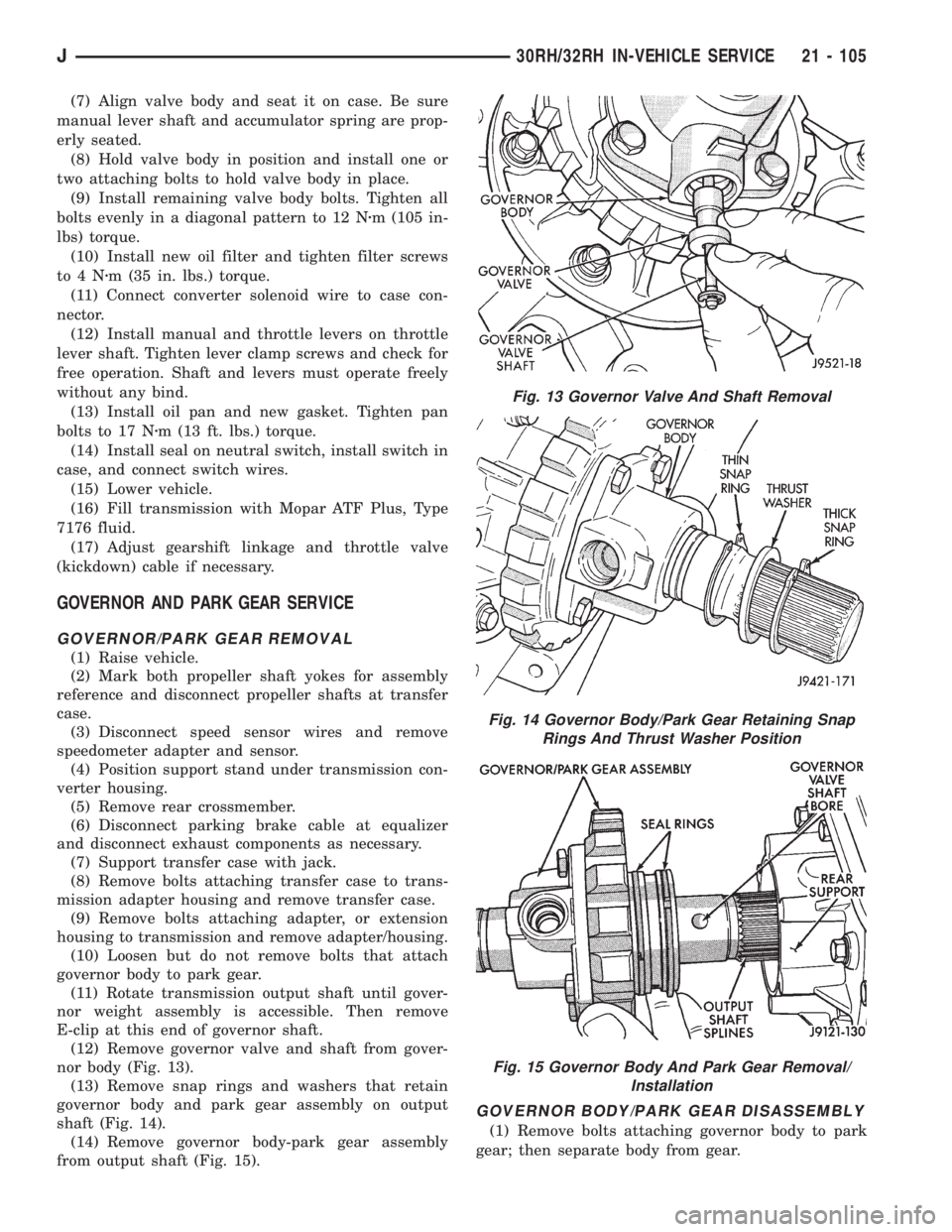
nor body (Fig. 13).
(13) Remove snap rings and washers that retain
governor body and park gear assembly on output
shaft (Fig. 14).
(14) Remove governor body-park gear assembly
from output shaft (Fig. 15).
GOVERNOR BODY/PARK GEAR DISASSEMBLY
(1) Remove bolts attaching governor body to park
gear; then separate body from gear.
Fig. 13 Governor Valve And Shaft Removal
Fig. 14 Governor Body/Park Gear Retaining Snap
Rings And Thrust Washer Position
Fig. 15 Governor Body And Park Gear Removal/
Installation
J30RH/32RH IN-VEHICLE SERVICE 21 - 105
Page 1687 of 2158
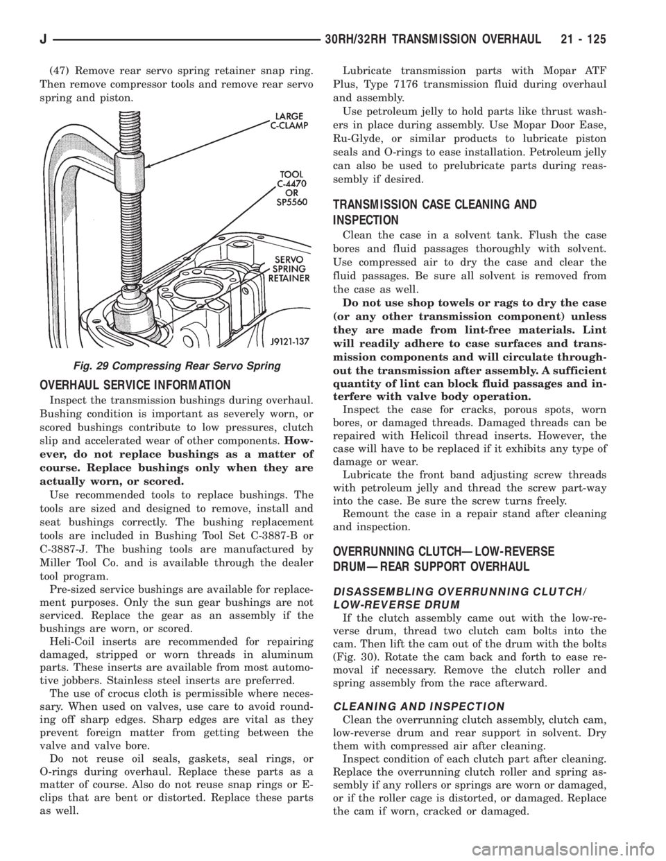
(47) Remove rear servo spring retainer snap ring.
Then remove compressor tools and remove rear servo
spring and piston.
OVERHAUL SERVICE INFORMATION
Inspect the transmission bushings during overhaul.
Bushing condition is important as severely worn, or
scored bushings contribute to low pressures, clutch
slip and accelerated wear of other components.How-
ever, do not replace bushings as a matter of
course. Replace bushings only when they are
actually worn, or scored.
Use recommended tools to replace bushings. The
tools are sized and designed to remove, install and
seat bushings correctly. The bushing replacement
tools are included in Bushing Tool Set C-3887-B or
C-3887-J. The bushing tools are manufactured by
Miller Tool Co. and is available through the dealer
tool program.
Pre-sized service bushings are available for replace-
ment purposes. Only the sun gear bushings are not
serviced. Replace the gear as an assembly if the
bushings are worn, or scored.
Heli-Coil inserts are recommended for repairing
damaged, stripped or worn threads in aluminum
parts. These inserts are available from most automo-
tive jobbers. Stainless steel inserts are preferred.
The use of crocus cloth is permissible where neces-
sary. When used on valves, use care to avoid round-
ing off sharp edges. Sharp edges are vital as they
prevent foreign matter from getting between the
valve and valve bore.
Do not reuse oil seals, gaskets, seal rings, or
O-rings during overhaul. Replace these parts as a
matter of course. Also do not reuse snap rings or E-
clips that are bent or distorted. Replace these parts
as well.Lubricate transmission parts with Mopar ATF
Plus, Type 7176 transmission fluid during overhaul
and assembly.
Use petroleum jelly to hold parts like thrust wash-
ers in place during assembly. Use Mopar Door Ease,
Ru-Glyde, or similar products to lubricate piston
seals and O-rings to ease installation. Petroleum jelly
can also be used to prelubricate parts during reas-
sembly if desired.
TRANSMISSION CASE CLEANING AND
INSPECTION
Clean the case in a solvent tank. Flush the case
bores and fluid passages thoroughly with solvent.
Use compressed air to dry the case and clear the
fluid passages. Be sure all solvent is removed from
the case as well.
Do not use shop towels or rags to dry the case
(or any other transmission component) unless
they are made from lint-free materials. Lint
will readily adhere to case surfaces and trans-
mission components and will circulate through-
out the transmission after assembly. A sufficient
quantity of lint can block fluid passages and in-
terfere with valve body operation.
Inspect the case for cracks, porous spots, worn
bores, or damaged threads. Damaged threads can be
repaired with Helicoil thread inserts. However, the
case will have to be replaced if it exhibits any type of
damage or wear.
Lubricate the front band adjusting screw threads
with petroleum jelly and thread the screw part-way
into the case. Be sure the screw turns freely.
Remount the case in a repair stand after cleaning
and inspection.
OVERRUNNING CLUTCHÐLOW-REVERSE
DRUMÐREAR SUPPORT OVERHAUL
DISASSEMBLING OVERRUNNING CLUTCH/
LOW-REVERSE DRUM
If the clutch assembly came out with the low-re-
verse drum, thread two clutch cam bolts into the
cam. Then lift the cam out of the drum with the bolts
(Fig. 30). Rotate the cam back and forth to ease re-
moval if necessary. Remove the clutch roller and
spring assembly from the race afterward.
CLEANING AND INSPECTION
Clean the overrunning clutch assembly, clutch cam,
low-reverse drum and rear support in solvent. Dry
them with compressed air after cleaning.
Inspect condition of each clutch part after cleaning.
Replace the overrunning clutch roller and spring as-
sembly if any rollers or springs are worn or damaged,
or if the roller cage is distorted, or damaged. Replace
the cam if worn, cracked or damaged.
Fig. 29 Compressing Rear Servo Spring
J30RH/32RH TRANSMISSION OVERHAUL 21 - 125
Page 1712 of 2158
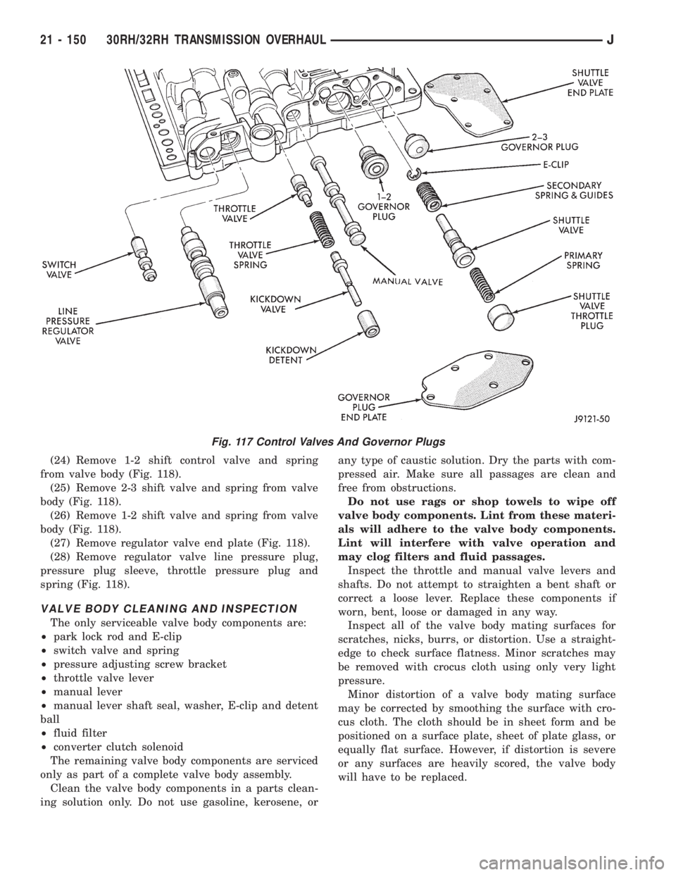
(24) Remove 1-2 shift control valve and spring
from valve body (Fig. 118).
(25) Remove 2-3 shift valve and spring from valve
body (Fig. 118).
(26) Remove 1-2 shift valve and spring from valve
body (Fig. 118).
(27) Remove regulator valve end plate (Fig. 118).
(28) Remove regulator valve line pressure plug,
pressure plug sleeve, throttle pressure plug and
spring (Fig. 118).
VALVE BODY CLEANING AND INSPECTION
The only serviceable valve body components are:
²park lock rod and E-clip
²switch valve and spring
²pressure adjusting screw bracket
²throttle valve lever
²manual lever
²manual lever shaft seal, washer, E-clip and detent
ball
²fluid filter
²converter clutch solenoid
The remaining valve body components are serviced
only as part of a complete valve body assembly.
Clean the valve body components in a parts clean-
ing solution only. Do not use gasoline, kerosene, orany type of caustic solution. Dry the parts with com-
pressed air. Make sure all passages are clean and
free from obstructions.
Do not use rags or shop towels to wipe off
valve body components. Lint from these materi-
als will adhere to the valve body components.
Lint will interfere with valve operation and
may clog filters and fluid passages.
Inspect the throttle and manual valve levers and
shafts. Do not attempt to straighten a bent shaft or
correct a loose lever. Replace these components if
worn, bent, loose or damaged in any way.
Inspect all of the valve body mating surfaces for
scratches, nicks, burrs, or distortion. Use a straight-
edge to check surface flatness. Minor scratches may
be removed with crocus cloth using only very light
pressure.
Minor distortion of a valve body mating surface
may be corrected by smoothing the surface with cro-
cus cloth. The cloth should be in sheet form and be
positioned on a surface plate, sheet of plate glass, or
equally flat surface. However, if distortion is severe
or any surfaces are heavily scored, the valve body
will have to be replaced.
Fig. 117 Control Valves And Governor Plugs
21 - 150 30RH/32RH TRANSMISSION OVERHAULJ