1995 JEEP YJ ABS
[x] Cancel search: ABSPage 101 of 2158

AXLE SPECIFICATIONS
MODEL 30 FRONT AXLE
Axle Type........................................................Hypoid
Lubricant................SAE Thermally Stable 80W-90
Lube Capacity
YJ .....................................................1.65 L (3.76 pts.)
XJ .....................................................1.48 L (3.13 pts.)
Axle Ratio...................................3.07 3.55 3.73 4.10
DifferentialSide Gear Clearance .0.12-0.20mm (0.005-0.008 in.)
Ring Gear
Diameter .....................................18.09 cm (7.125 in.)
Backlash.........................0-0.15 mm (0.005-0.008 in.)
Pinion Std. Depth...................92.1 mm (3.625 in.)
Pinion Bearing Preload
Original Bearing ..................1-2 Nzm (10-20 in. lbs.)
New Bearing ......................1.5-4 Nzm (15-35 in. lbs.)
TORQUE SPECIFICATIONS
XJ FRONT SUSPENSION COMPONENTS
DESCRIPTION ................................................TORQUE
Shock Absorber
Upper Nut ......................................11 Nzm (8 ft. lbs.)
Lower Nut ....................................23 Nzm (17 ft. lbs.)
Suspension Arm Upper
Front Nut .....................................74 Nzm (55 ft. lbs.)
Rear Nut ......................................89 Nzm (66 ft. lbs.)
Suspension Arm Lower
Front and Rear Nut ..................115 Nzm (85 ft. lbs.)
Stabilizer Bar
Clamp Bolt ...................................54 Nzm (40 ft. lbs.)
Link Upper Nut ..........................36 Nzm (27 ft. lbs.)
Link Lower Nut ..........................95 Nzm (70 ft. lbs.)
Track Bar
Ball Stud Nut ..............................81 Nzm (60 ft. lbs.)
Axle Bracket Bolt ......................100 Nzm (74 ft. lbs.)
Track Bar Bracket
Bolts............................................125 Nzm (92 ft. lbs.)
Nut ..............................................100 Nzm (74 ft. lbs.)
Support Bolts ...............................42 Nzm (31 ft. lbs.)
YJ FRONT SUSPENSION COMPONENTS
DESCRIPTION ................................................TORQUE
Shock Absorber
Upper Nut ......................................13 Nzm (9 ft. lbs.)Lower Nut ....................................61 Nzm (45 ft. lbs.)
Stabilizer Bar
Clamp Bolt ...................................41 Nzm (30 ft. lbs.)
Link Nut ......................................61 Nzm (45 ft. lbs.)
Track Bar
Frame Bracket Nut.................142 Nzm (105 ft. lbs.)
Axle Bracket Nut ......................100 Nzm (74 ft. lbs.)
Spring
U-Bolt Nut .................................122 Nzm (90 ft. lbs.)
Front Shackle Bolt ..................135 Nzm (100 ft. lbs.)
Rear Pivot Bolt........................142 Nzm (105 ft. lbs.)
MODEL 30 AXLE
DESCRIPTION ................................................TORQUE
Fill Hole Plug...........................34 Nzm (25 ft. lbs.)
Diff. Cover Bolt........................41 Nzm (30 ft. lbs.)
Bearing Cap Bolt.....................61 Nzm (45 ft. lbs.)
Ring Gear Bolt.............95-122 Nzm (70-90 ft. lbs.)
Shift Motor Bolt.........................11 Nzm (8 ft. lbs.)
Axle Nut.................................237 Nzm (175 ft. lbs.)
Wheel Brg. Bolt......................102 Nzm (75 ft. lbs.)
Lower Ball Stud.....................108 Nzm (80 ft. lbs.)
Upper Ball Stud.....................101 Nzm (75 ft. lbs.)
ABS Sensor Bolt......................11 Nzm (96 in. lbs.)
JFRONT SUSPENSION AND AXLE 2 - 49
Page 102 of 2158
REAR SUSPENSION AND AXLES
CONTENTS
page page
8 1/4 AXLE............................ 30
AXLE NOISE/VIBRATION DIAGNOSIS......... 9
AXLE SPECIFICATIONS................... 51
GENERAL INFORMATION.................. 1
MODEL 35 AXLE........................ 13TORQUE SPECIFICATIONS................ 51
TRAC-LOK DIFFERENTIAL................. 45
XJ SUSPENSION......................... 3
YJ SUSPENSION......................... 6
GENERAL INFORMATION
SUSPENSION COMPONENTS
The Jeep rear suspension is comprised of;
²Drive axle
²Leaf springs
²Dual-action shock absorbers
²Track bar (YJ vehicles)
²Stabilizer bar (XJ vehicles)
²Jounce bumpers
The rear suspension design uses semi-elliptic
multi-leaf springs and a solid drive axle. The forward
end of the springs are mounted to the frame rail
hangers through rubber bushings. The bushings iso-
late road noise as the springs move. The rearward
end of the springs are attached to the frame by the
use of shackles. Again the spring and shackles use
rubber bushings to isolate road noise. The shackles
allow the springs to change their length as the vehi-
cle moves over various road conditions. The spring
and axle travel is limited through the use of bumpers
mounted on frame.
All suspension components that use bushings
should be tightened with the vehicle at normal ride
height. If the springs are not at normal ride position,
vehicle ride comfort could be affected. Rubber bush-
ings must never be lubricated.
The springs are attached to the axle pads with U-
bolts and plates. The springs use a center bolt that
holds the spring leafs in position. The bolt is also
used to locate the spring assembly to the axle pad.
Ride control is accomplished through the use of du-
al-action shock absorbers. The shocks dampen the
jounce and rebound as the vehicle travels over vari-
ous road conditions. The top of shock absorbers are
bolted to the frame bracket. The bottom of the shocks
are bolted to the axle bracket.
The stabilizer bar on the XJ is used to minimize
vehicle rear sway during turns. The bar helps the ve-
hicle maintain a flat attitude to the road surface. The
bar extends across the underside of the chassis and
connects to the frame rails. The links are connectedto the axle brackets. All mounting points of the sta-
bilizer bar are isolated by bushings.
The track bar on the YJ is used to minimize rear
axle side-to-side movement. The track bar is attached
to the frame rail bracket and axle bracket and is iso-
lated with bushings.
The jounce bumpers are used to limit the jounce
and rebound travel of the suspension.
AXLES
The Model 35 axle is standard for XJ and YJ vehi-
cles. The 8 1/4 axle is available in XJ vehicles with-
out ABS brakes.
The Model 35 and 8 1/4 axle housings has a cast
iron center section. Two steel axle shaft tubes are
pressed into the differential housing and welded.
It is not necessary to remove the axle from the ve-
hicle for service. A removable differential cover is
provided for routine vehicle service. If the differential
housing is damaged, the complete axle assembly can
be removed.
For complete drive axle assembly removal and in-
stallation refer to Drive Axle Assembly Replacement
in this Group.
IDENTIFICATION
Model 35 axle has the assembly part number and
gear ratio listed on a tag. The tag is attached to the left
side of the housing cover (Fig. 1). Build date identifica-
tion codes on axles are stamped on the axle shaft tube
cover side. The Model 35 axle has a flat housing cover
gasket flange at the outer edge (Fig. 1).
The 8 1/4 axle has the build date code and gear ra-
tio tags attached to the housing cover (Fig. 2). The
housing cover gasket has a rolled gasket flange at
the outer edge (Fig. 2).
²The Model 35 axle has shaft tubes that are 2.625
inch (66.67 mm) in diameter.
²The 8 1/4 axle has axle shaft tubes that are 3.0-
inch (76.2 mm) in diameter.
JREAR SUSPENSION AND AXLES 3 - 1
Page 104 of 2158
XJ SUSPENSION
INDEX
page page
Leaf Spring............................... 4
Leaf Spring Eye Bushing Replacement.......... 5
Shock Absorber........................... 4Spring and Shock Diagnosis.................. 3
Stabilizer Bar............................. 5
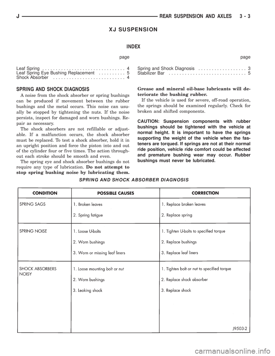
SPRING AND SHOCK DIAGNOSIS
A noise from the shock absorber or spring bushings
can be produced if movement between the rubber
bushings and the metal occurs. This noise can usu-
ally be stopped by tightening the nuts. If the noise
persists, inspect for damaged and worn bushings. Re-
pair as necessary.
The shock absorbers are not refillable or adjust-
able. If a malfunction occurs, the shock absorber
must be replaced. To test a shock absorber, hold it in
an upright position and force the piston into and out
of the cylinder four or five times. The action through-
out each stroke should be smooth and even.
The spring eye and shock absorber bushings do not
require any type of lubrication.Do not attempt to
stop spring bushing noise by lubricating them.Grease and mineral oil-base lubricants will de-
teriorate the bushing rubber.
If the vehicle is used for severe, off-road operation,
the springs should be examined regularly. Check for
broken and shifted components.
CAUTION: Suspension components with rubber
bushings should be tightened with the vehicle at
normal height. It is important to have the springs
supporting the weight of the vehicle when the fas-
teners are torqued. If springs are not at their normal
ride position, vehicle ride comfort could be affected
and premature bushing wear may occur. Rubber
bushings must never be lubricated.
SPRING AND SHOCK ABSORBER DIAGNOSIS
JREAR SUSPENSION AND AXLES 3 - 3
Page 105 of 2158
SHOCK ABSORBER
REMOVAL
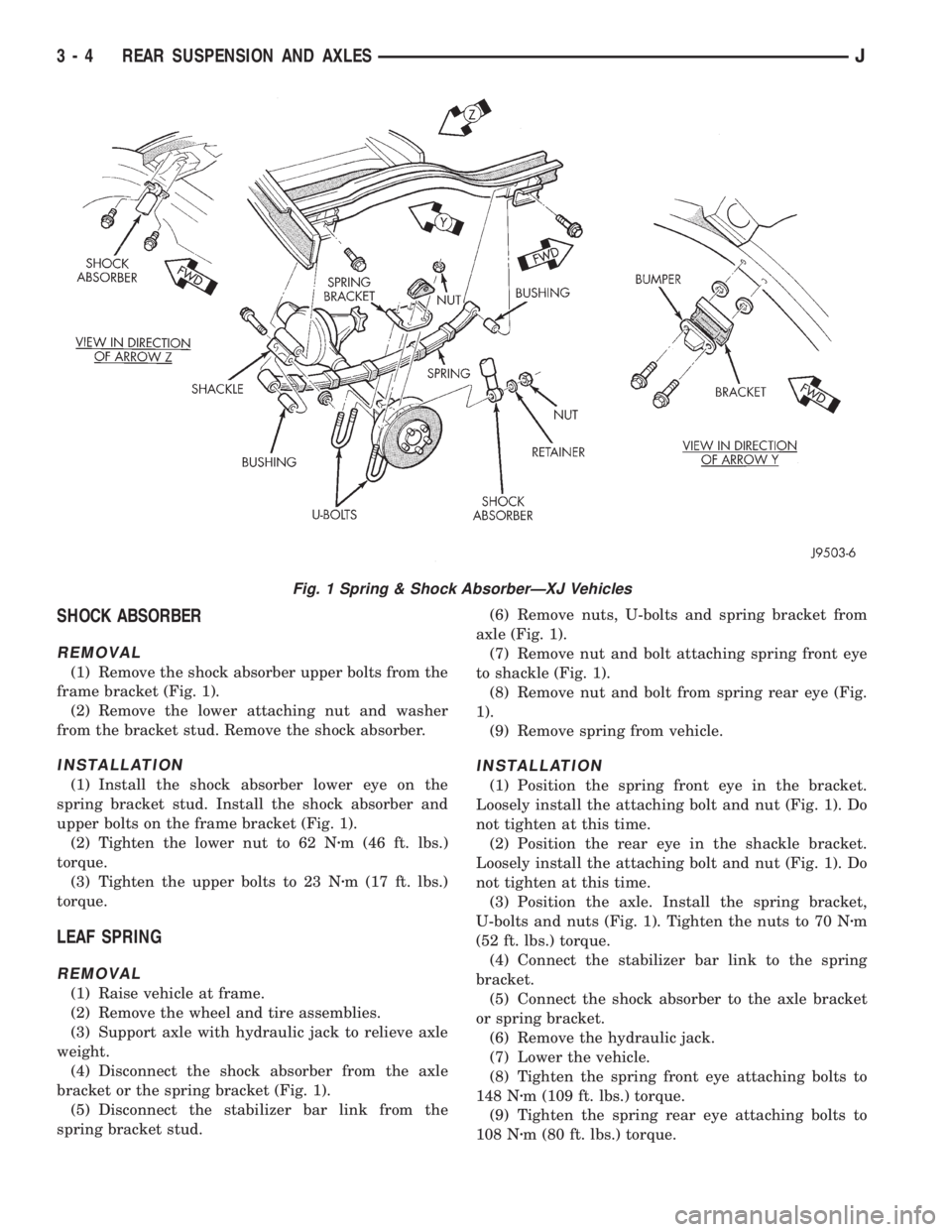
(1) Remove the shock absorber upper bolts from the
frame bracket (Fig. 1).
(2) Remove the lower attaching nut and washer
from the bracket stud. Remove the shock absorber.
INSTALLATION
(1) Install the shock absorber lower eye on the
spring bracket stud. Install the shock absorber and
upper bolts on the frame bracket (Fig. 1).
(2) Tighten the lower nut to 62 Nzm (46 ft. lbs.)
torque.
(3) Tighten the upper bolts to 23 Nzm (17 ft. lbs.)
torque.
LEAF SPRING
REMOVAL
(1) Raise vehicle at frame.
(2) Remove the wheel and tire assemblies.
(3) Support axle with hydraulic jack to relieve axle
weight.
(4) Disconnect the shock absorber from the axle
bracket or the spring bracket (Fig. 1).
(5) Disconnect the stabilizer bar link from the
spring bracket stud.(6) Remove nuts, U-bolts and spring bracket from
axle (Fig. 1).
(7) Remove nut and bolt attaching spring front eye
to shackle (Fig. 1).
(8) Remove nut and bolt from spring rear eye (Fig.
1).
(9) Remove spring from vehicle.
INSTALLATION
(1) Position the spring front eye in the bracket.
Loosely install the attaching bolt and nut (Fig. 1). Do
not tighten at this time.
(2) Position the rear eye in the shackle bracket.
Loosely install the attaching bolt and nut (Fig. 1). Do
not tighten at this time.
(3) Position the axle. Install the spring bracket,
U-bolts and nuts (Fig. 1). Tighten the nuts to 70 Nzm
(52 ft. lbs.) torque.
(4) Connect the stabilizer bar link to the spring
bracket.
(5) Connect the shock absorber to the axle bracket
or spring bracket.
(6) Remove the hydraulic jack.
(7) Lower the vehicle.
(8) Tighten the spring front eye attaching bolts to
148 Nzm (109 ft. lbs.) torque.
(9) Tighten the spring rear eye attaching bolts to
108 Nzm (80 ft. lbs.) torque.
Fig. 1 Spring & Shock AbsorberÐXJ Vehicles
3 - 4 REAR SUSPENSION AND AXLESJ
Page 107 of 2158
YJ SUSPENSION
INDEX
page page
Leaf Spring............................... 7
Leaf Spring Eye Bushing Replacement.......... 7
Shock Absorber........................... 7Spring and Shock Diagnosis.................. 6
Track Bar................................ 8
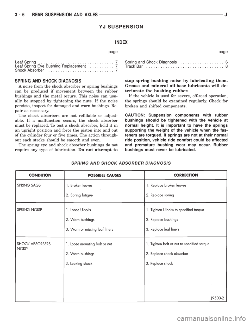
SPRING AND SHOCK DIAGNOSIS
A noise from the shock absorber or spring bushings
can be produced if movement between the rubber
bushings and the metal occurs. This noise can usu-
ally be stopped by tightening the nuts. If the noise
persists, inspect for damaged and worn bushings. Re-
pair as necessary.
The shock absorbers are not refillable or adjust-
able. If a malfunction occurs, the shock absorber
must be replaced. To test a shock absorber, hold it in
an upright position and force the piston into and out
of the cylinder four or five times. The action through-
out each stroke should be smooth and even.
The spring eye and shock absorber bushings do not
require any type of lubrication.Do not attempt tostop spring bushing noise by lubricating them.
Grease and mineral oil-base lubricants will de-
teriorate the bushing rubber.
If the vehicle is used for severe, off-road operation,
the springs should be examined regularly. Check for
broken and shifted components.
CAUTION: Suspension components with rubber
bushings should be tightened with the vehicle at
normal height. It is important to have the springs
supporting the weight of the vehicle when the fas-
teners are torqued. If springs are not at their normal
ride position, vehicle ride comfort could be affected
and premature bushing wear may occur. Rubber
bushings must never be lubricated.
SPRING AND SHOCK ABSORBER DIAGNOSIS
3 - 6 REAR SUSPENSION AND AXLESJ
Page 108 of 2158
SHOCK ABSORBER
REMOVAL
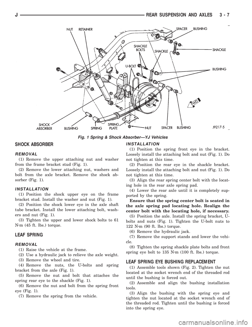
(1) Remove the upper attaching nut and washer
from the frame bracket stud (Fig. 1).
(2) Remove the lower attaching nut, washers and
bolt from the axle bracket. Remove the shock ab-
sorber (Fig. 1).
INSTALLATION
(1) Position the shock upper eye on the frame
bracket stud. Install the washer and nut (Fig. 1).
(2) Position the shock lower eye in the axle shaft
tube bracket. Install the lower attaching bolt, wash-
ers and nut (Fig. 1).
(3) Tighten the upper and lower shock bolts to 61
Nzm (45 ft. lbs.) torque.
LEAF SPRING
REMOVAL
(1) Raise the vehicle at the frame.
(2) Use a hydraulic jack to relieve the axle weight.
(3) Remove the wheel and tire.
(4) Remove the nuts, the U-bolts and spring
bracket from the axle (Fig. 1).
(5) Remove the nut and bolt that attaches the
spring rear eye to the shackle (Fig. 1).
(6) Remove the nut and bolt from the spring front
eye (Fig. 1).
(7) Remove the spring from the vehicle.
INSTALLATION
(1) Position the spring front eye in the bracket.
Loosely install the attaching bolt and nut (Fig. 1). Do
not tighten at this time.
(2) Position the rear eye in the shackle bracket.
Loosely install the attaching bolt and nut (Fig. 1). Do
not tighten at this time.
(3) Align the rear spring center bolt with the locat-
ing hole in the rear axle spring pad.
(4) Lower the rear axle until it is completely sup-
ported by the spring.
Ensure that the spring center bolt is seated in
the axle spring pad locating hole. Realign the
center bolt with the locating hole, if necessary.
(5) Position the axle. Install the spring bracket, U-
bolts and nuts (Fig. 1). Tighten the U-bolt nuts to
122 Nzm (90 ft. lbs.) torque.
(6) Remove the hydraulic jack.
(7) Remove the support stands and lower the vehi-
cle.
(8) Tighten the spring shackle plate bolts and front
spring eye bolt to 135 Nzm (100 ft. lbs.) torque.
LEAF SPRING EYE BUSHING REPLACEMENT
(1) Assemble tools shown (Fig. 2). Tighten the nut
located at the socket wrench end of the threaded rod
until the bushing is forced out.
(2) Assemble and align the bushing installation
tools.
(3) Align the bushing with the spring eye and
tighten the nut located at the socket wrench end of
the threaded rod. Tighten until the bushing is forced
into the spring eye.
Fig. 1 Spring & Shock AbsorberÐYJ Vehicles
JREAR SUSPENSION AND AXLES 3 - 7
Page 114 of 2158

MODEL 35 AXLE
INDEX
page page
Axle Shaft............................... 16
Axle Shaft Seal and Bearing................. 17
Backlash and Contact Pattern Analysis......... 27
Cleaning/Inspection........................ 20
Differential Assembly....................... 21
Differential Disassembly.................... 18
Differential Measurement and Installation........ 25
Differential Removal....................... 18
Drive Axle Assembly ReplacementÐXJ Vehicles . . 14Drive Axle Assembly ReplacementÐYJ Vehicles . . 14
Final Assembly........................... 29
General Information....................... 13
Lubricant Change......................... 13
Lubricant Specifications..................... 13
Pinion Gear Depth Information............... 21
Pinion Measurement and Assembly............ 22
Pinion Removal/Disassembly................. 19
Pinion Shaft Seal Replacement............... 15
GENERAL INFORMATION
The Model 35 housing has an iron center casting
(differential housing) with axle shaft tubes extending
from either side. The tubes are pressed into and
welded to the differential housing to form a one-piece
axle housing.
The integral type housing, hypoid gear design has
the centerline of the pinion set below the centerline
of the ring gear.
The axle has a vent hose to relieve internal pres-
sure caused by lubricant vaporization and internal
expansion.
The axles are equipped with semi-floating axle
shafts, meaning that loads are supported by the axle
shaft and bearings. The axle shafts are retained by
C-clips in the differential side gears.
The cover provides a means for servicing the differ-
ential without removing the axle.
Axles may be equipped with drum or disc brakes.
The axles that are equipped with ABS brake have a
tone ring pressed on the axle shaft. Use care when
removing axle shafts as NOT to damage the tone
wheel or the sensor.
The Model 35 axle has the assembly part number
and gear ratio listed on a tag. The tag is attached to
the housing cover. Build date identification codes are
stamped on the axle shaft tube cover side.
The differential case is a one-piece design. The dif-
ferential pinion mate shaft is retained with a
threaded roll pin. Differential bearing preload and
ring gear backlash is adjusted by the use of spacer
shims. Pinion bearing preload is set and maintained
by the use of a collapsible spacer.
For complete drive axle assembly removal
and installation refer to Drive Axle Assembly
Replacement in this Group.
LUBRICANT SPECIFICATIONS
Multi-purpose, hypoid gear lubricant should be
used for Model 35 axle. The lubricant should haveMIL-L-2105C and API GL 5 quality specifications.
MOPAR Hypoid Gear Lubricant conforms to both of
these specifications.
²Lubricant for Model 35 axle is a thermally stable
SAE 80W-90 gear lubricant.
²Lubricant for Model 35 axle with Trailer Tow is
SAE 75W-140 SYNTHETIC gear lubricant.
²Trac-Lok differentials add 4 oz. of friction modifier.
²Lubricant quantity is 1.66 L (3.50 pts.).
Refer to Group 0, Lubrication and Maintenance for
additional information.
CAUTION: If axle is submerged in water, lubricant
must be replaced immediately to avoid possible
premature axle failure.
LUBRICANT CHANGE
The gear lubricant will drain quicker if the vehicle
has been recently driven.
(1) Raise and support the vehicle.
(2) Remove the lubricant fill hole plug from the dif-
ferential housing cover.
(3) Remove the differential housing cover and
drain the lubricant from the housing.
(4) Clean the housing cavity with a flushing oil,
light engine oil or lint free cloth.Do not use water,
steam, kerosene or gasoline for cleaning.
(5) Remove the sealant from the housing and cover
surfaces.
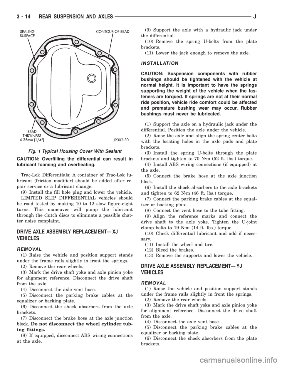
(6) Apply a bead of MOPARtSilicone Rubber Seal-
ant to the housing cover (Fig. 1).Allow the sealant
to cure for a few minutes.
Install the housing cover within 5 minutes af-
ter applying the sealant. If not installed the
sealant must be removed and another bead ap-
plied.
(7) Install the cover and any identification tag.
Tighten the cover bolts to 41 Nzm (30 ft. lbs.) torque.
(8) Refill differential with Mopar Hypoid Gear Lu-
bricant to bottom of the fill plug hole.
JREAR SUSPENSION AND AXLES 3 - 13
Page 115 of 2158
CAUTION: Overfilling the differential can result in
lubricant foaming and overheating.
Trac-Lok Differentials; A container of Trac-Lok lu-
bricant (friction modifier) should be added after re-
pair service or a lubricant change.
(9) Install the fill hole plug and lower the vehicle.
LIMITED SLIP DIFFERENTIAL vehicles should
be road tested by making 10 to 12 slow figure-eight
turns. This maneuver will pump the lubricant
through the clutch discs to eliminate a possible chat-
ter noise complaint.
DRIVE AXLE ASSEMBLY REPLACEMENTÐXJ
VEHICLES
REMOVAL
(1) Raise the vehicle and position support stands
under the frame rails slightly in front the springs.
(2) Remove the rear wheels.
(3) Mark the drive shaft yoke and axle pinion yoke
for alignment reference. Disconnect the drive shaft
from the axle.
(4) Disconnect the axle vent hose.
(5) Disconnect the parking brake cables at the
equalizer or backing plate.
(6) Disconnect the shock absorbers from the axle
brackets.
(7) Disconnect the brake hose at the axle junction
block.Do not disconnect the wheel cylinder tub-
ing fittings.
(8) If equipped, disconnect ABS wiring connections
at the axle.(9) Support the axle with a hydraulic jack under
the differential.
(10) Remove the spring U-bolts from the plate
brackets.
(11) Lower the jack enough to remove the axle.
INSTALLATION
CAUTION: Suspension components with rubber
bushings should be tightened with the vehicle at
normal height. It is important to have the springs
supporting the weight of the vehicle when the fas-
teners are torqued. If springs are not at their normal
ride position, vehicle ride comfort could be affected
and premature bushing wear may occur. Rubber
bushings must never be lubricated.
(1) Support the axle on a hydraulic jack under the
differential. Position the axle under the vehicle.
(2) Raise the axle and align the spring center bolts
with the locating holes in the axle pads and plate
brackets.
(3) Install the spring U-bolts through the plate
brackets and tighten to 70 Nzm (52 ft. lbs.) torque.
(4) Install ABS wiring connections (if equipped) at
the axle.
(5) Connect the brake hose at the axle junction
block.
(6) Install the shock absorbers to the axle brackets
and tighten to 62 Nzm (46 ft. lbs.) torque.
(7) Connect the parking brake cables at the equal-
izer or backing plate.
(8) Connect the vent hose to the tube fitting.
(9) Align the reference marks and connect the
drive shaft to the axle yoke. Tighten the U-joint
clamp bolts to 19 Nzm (14 ft. lbs.) torque.
(10) Check differential lubricant and add if neces-
sary.
(11) Install the wheel and tire.
(12) Bleed the brakes.
(13) Remove the supports and lower the vehicle.
DRIVE AXLE ASSEMBLY REPLACEMENTÐYJ
VEHICLES
REMOVAL
(1) Raise the vehicle and position support stands
under the frame rails slightly in front the springs.
(2) Remove the rear wheels.
(3) Mark the drive shaft yoke and axle pinion yoke
for alignment reference. Disconnect the drive shaft
from the axle.
(4) Disconnect the axle vent hose.
(5) Disconnect the parking brake cables at the
equalizer or backing plate.
(6) Disconnect the shock absorbers from the plate
brackets.
Fig. 1 Typical Housing Cover With Sealant
3 - 14 REAR SUSPENSION AND AXLESJ