1995 JEEP YJ body panel emoval
[x] Cancel search: body panel emovalPage 1379 of 2158
INSTALLATION
(1) Assemble exhaust pipe to manifold and cata-
lytic converter loosely to permit proper alignment of
all parts.
(2) Use a new clamp and tighten the nuts to 61
Nzm (45 ft. lbs.) torque.
(3) Connect the exhaust pipe to the engine exhaust
manifold. Install a new seal between the exhaust
manifold and the exhaust pipe (4.0L engine, only).
Tighten the nuts to 31 Nzm (23 ft. lbs.) torque (Fig.
1).
(3) Install the rear crossmember. Tighten the
crossmember-to-sill bolts to 41 Nzm (30 ft. lbs.)
torque. Remove the support from the transmission.
(4) Coat the oxygen sensor with anti-seize com-
pound. Install the sensor and tighten the nut to 48
Nzm (35 ft. lbs.) torque.
(5) Lower the vehicle.
(6) Start the engine and inspect for exhaust leaks
and exhaust system contact with the body panels.
Adjust the alignment, if needed.
EXHAUST PIPEÐYJ VEHICLES
WARNING: IF TORCHES ARE USED WHEN WORK-
ING ON THE EXHAUST SYSTEM, DO NOT ALLOW
THE FLAME NEAR THE FUEL LINES.
REMOVAL
(1) Raise and support the vehicle.
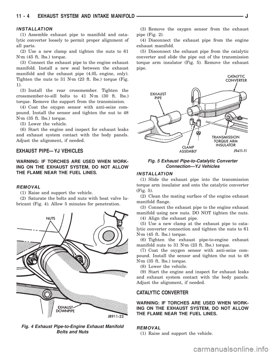
(2) Saturate the bolts and nuts with heat valve lu-
bricant (Fig. 4). Allow 5 minutes for penetration.(3) Remove the oxygen sensor from the exhaust
pipe (Fig. 2).
(4) Disconnect the exhaust pipe from the engine
exhaust manifold.
(5) Disconnect the exhaust pipe from the catalytic
converter and slide the pipe out of the transmission
torque arm insulator (Fig. 5). Remove the exhaust
pipe.
INSTALLATION
(1) Slide the exhaust pipe into the transmission
torque arm insulator and onto the catalytic converter
(Fig. 5).
(2) Clean the mating surface of the engine exhaust
manifold flange.
(3) Connect the exhaust pipe to the engine exhaust
manifold using new nuts. DO NOT tighten the nuts.
(4) Align the exhaust pipe.
(5) Use a new clamp at the exhaust pipe to cata-
lytic converter connection and tighten the nuts to 61
Nzm (45 ft. lbs.) torque.
(6) Tighten the exhaust pipe-to-engine exhaust
manifold nuts to 31 Nzm (23 ft. lbs.) torque.
(7) Coat the oxygen sensor with anti-seize com-
pound. Install the sensor and tighten the nut to 48
Nzm (35 ft. lbs.) torque.
(8) Lower the vehicle.
(9) Start the engine and inspect for exhaust leaks
and exhaust system contact with the body panels.
Adjust the alignment, if needed.
CATALYTIC CONVERTER
WARNING: IF TORCHES ARE USED WHEN WORK-
ING ON THE EXHAUST SYSTEM, DO NOT ALLOW
THE FLAME NEAR THE FUEL LINES.
REMOVAL
(1) Raise and support the vehicle.
Fig. 4 Exhaust Pipe-to-Engine Exhaust Manifold
Bolts and Nuts
Fig. 5 Exhaust Pipe-to-Catalytic Converter
ConnectionÐYJ Vehicles
11 - 4 EXHAUST SYSTEM AND INTAKE MANIFOLDJ
Page 1380 of 2158
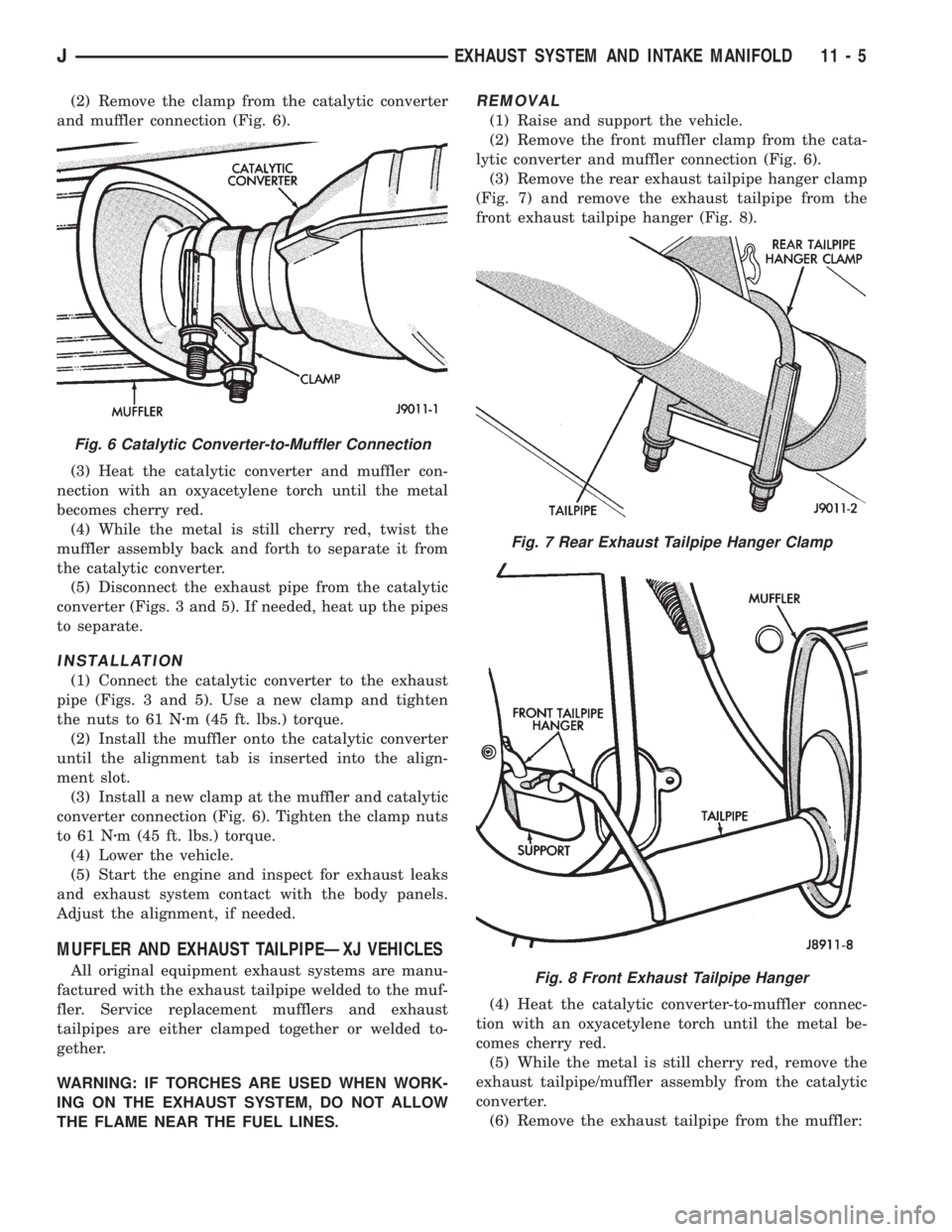
(2) Remove the clamp from the catalytic converter
and muffler connection (Fig. 6).
(3) Heat the catalytic converter and muffler con-
nection with an oxyacetylene torch until the metal
becomes cherry red.
(4) While the metal is still cherry red, twist the
muffler assembly back and forth to separate it from
the catalytic converter.
(5) Disconnect the exhaust pipe from the catalytic
converter (Figs. 3 and 5). If needed, heat up the pipes
to separate.
INSTALLATION
(1) Connect the catalytic converter to the exhaust
pipe (Figs. 3 and 5). Use a new clamp and tighten
the nuts to 61 Nzm (45 ft. lbs.) torque.
(2) Install the muffler onto the catalytic converter
until the alignment tab is inserted into the align-
ment slot.
(3) Install a new clamp at the muffler and catalytic
converter connection (Fig. 6). Tighten the clamp nuts
to 61 Nzm (45 ft. lbs.) torque.
(4) Lower the vehicle.
(5) Start the engine and inspect for exhaust leaks
and exhaust system contact with the body panels.
Adjust the alignment, if needed.
MUFFLER AND EXHAUST TAILPIPEÐXJ VEHICLES
All original equipment exhaust systems are manu-
factured with the exhaust tailpipe welded to the muf-
fler. Service replacement mufflers and exhaust
tailpipes are either clamped together or welded to-
gether.
WARNING: IF TORCHES ARE USED WHEN WORK-
ING ON THE EXHAUST SYSTEM, DO NOT ALLOW
THE FLAME NEAR THE FUEL LINES.
REMOVAL
(1) Raise and support the vehicle.
(2) Remove the front muffler clamp from the cata-
lytic converter and muffler connection (Fig. 6).
(3) Remove the rear exhaust tailpipe hanger clamp
(Fig. 7) and remove the exhaust tailpipe from the
front exhaust tailpipe hanger (Fig. 8).
(4) Heat the catalytic converter-to-muffler connec-
tion with an oxyacetylene torch until the metal be-
comes cherry red.
(5) While the metal is still cherry red, remove the
exhaust tailpipe/muffler assembly from the catalytic
converter.
(6) Remove the exhaust tailpipe from the muffler:
Fig. 6 Catalytic Converter-to-Muffler Connection
Fig. 7 Rear Exhaust Tailpipe Hanger Clamp
Fig. 8 Front Exhaust Tailpipe Hanger
JEXHAUST SYSTEM AND INTAKE MANIFOLD 11 - 5
Page 1381 of 2158
²To remove an original equipment exhaust tailpipe/
muffler combination, cut the exhaust tailpipe close to
the muffler. Collapse the part remaining in the muf-
fler and remove.
²To remove a service exhaust tailpipe/muffler com-
bination, apply heat until the metal becomes cherry
red. Remove the exhaust tailpipe/muffler clamp and
twist the exhaust tailpipe out of the muffler.
INSTALLATION
(1) Install the muffler onto the catalytic converter.
Install the clamp and tighten the nuts finger tight.
(2) Install the exhaust tailpipe into the rear of the
muffler.
(3) Install the exhaust tailpipe/muffler assembly on
the rear exhaust tailpipe hanger. Make sure that the
exhaust tailpipe has sufficient clearance from the
floor pan.
(4) Install the remaining clamps and the front ex-
haust tailpipe hanger.
(5) Tighten the nuts on the muffler-to-catalytic
converter clamp to 61 Nzm (45 ft. lbs.) torque (Fig. 6).
Tighten the nuts on the rear exhaust tailpipe clamp
to 14 Nzm (10 ft. lbs.) torque (Fig. 7).
(6) Lower the vehicle.
(7) Start the engine and inspect for exhaust leaks
and exhaust system contact with the body panels.
Adjust the alignment, if needed.
MUFFLER AND EXHAUST TAILPIPEÐYJ VEHICLES
All original equipment exhaust systems are manu-
factured with the exhaust tailpipe welded to the muf-
fler. Service replacement mufflers and exhaust
tailpipes are clamped together.
WARNING: IF TORCHES ARE USED WHEN WORK-
ING ON THE EXHAUST SYSTEM, DO NOT ALLOW
THE FLAME NEAR THE FUEL LINES.
REMOVAL
(1) Raise the vehicle and support the rear of the
vehicle by the side rails and allow the axle to hang
free.
(2) Remove the front muffler clamp from the cata-
lytic converter and muffler connection (Fig. 6).
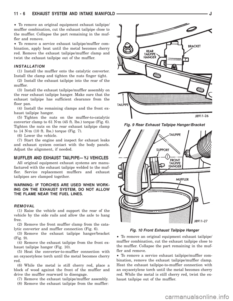
(3) Remove the exhaust tailpipe hanger/bracket
(Fig. 9).
(4) Remove the exhaust tailpipe from the front ex-
haust tailpipe hanger (Fig. 10).
(5) Heat the converter-to-muffler connection with
an oxyacetylene torch until the metal becomes cherry
red.
(6) While the metal is still cherry red, place a
block of wood against the front of the muffler and
drive the muffler rearward to disengage.
(7) Remove the exhaust tailpipe/muffler assembly.
(8) Remove the exhaust tailpipe from the muffler:²To remove an original equipment exhaust tailpipe/
muffler combination, cut the exhaust tailpipe close to
the muffler. Collapse the part remaining in the muf-
fler and remove.
²To remove a service exhaust tailpipe/muffler com-
bination, remove the exhaust tailpipe/muffler clamp.
Heat the exhaust tailpipe-to-muffler connection with
an oxyacetylene torch until the metal becomes cherry
red. While the metal is still cherry red, twist the ex-
haust tailpipe out of the muffler.
Fig. 9 Rear Exhaust Tailpipe Hanger/Bracket
Fig. 10 Front Exhaust Tailpipe Hanger
11 - 6 EXHAUST SYSTEM AND INTAKE MANIFOLDJ
Page 1382 of 2158
INSTALLATION
(1) Install the muffler onto the catalytic converter
outlet. Ensure that the locator on the converter
aligns with the notch on the muffler, if so equipped.
Install the clamp and tighten the nuts finger tight.
(2) Install the exhaust tailpipe into the muffler
outlet. Ensure that the locator on the exhaust
tailpipe aligns with the notch on the muffler, if so
equipped. Install the clamp and tighten the nuts fin-
ger tight.
(3) Install the front exhaust tailpipe supports and
the rear exhaust tailpipe hanger. Ensure that the ex-
haust tailpipe has sufficient clearance from the floor
pan and shields.
(4) Tighten the nuts on the muffler-to-catalytic
converter and the muffler-to-exhaust tailpipe clamps
to 61 Nzm (45 ft. lbs.) torque.
(5) Lower the vehicle.
(6) Start the engine and inspect for exhaust leaks
and contact with the body panels and shields.
ENGINE EXHAUST MANIFOLDÐ2.5L ENGINE
REMOVAL
(1) Disconnect the battery negative cable.
(2) Remove all components attached to the intake
manifold.
(3) Raise the vehicle.
(4) Disconnect the exhaust pipe from the engine
exhaust manifold.
(5) Lower the vehicle.
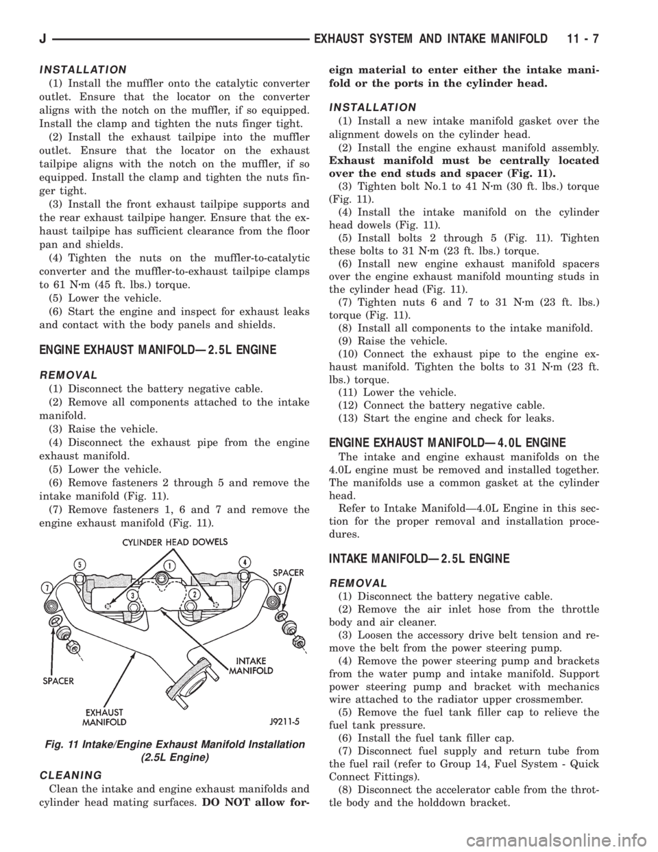
(6) Remove fasteners 2 through 5 and remove the
intake manifold (Fig. 11).
(7) Remove fasteners 1, 6 and 7 and remove the
engine exhaust manifold (Fig. 11).
CLEANING
Clean the intake and engine exhaust manifolds and
cylinder head mating surfaces.DO NOT allow for-eign material to enter either the intake mani-
fold or the ports in the cylinder head.
INSTALLATION
(1) Install a new intake manifold gasket over the
alignment dowels on the cylinder head.
(2) Install the engine exhaust manifold assembly.
Exhaust manifold must be centrally located
over the end studs and spacer (Fig. 11).
(3) Tighten bolt No.1 to 41 Nzm (30 ft. lbs.) torque
(Fig. 11).
(4) Install the intake manifold on the cylinder
head dowels (Fig. 11).
(5) Install bolts 2 through 5 (Fig. 11). Tighten
these bolts to 31 Nzm (23 ft. lbs.) torque.
(6) Install new engine exhaust manifold spacers
over the engine exhaust manifold mounting studs in
the cylinder head (Fig. 11).
(7) Tighten nuts 6 and 7 to 31 Nzm (23 ft. lbs.)
torque (Fig. 11).
(8) Install all components to the intake manifold.
(9) Raise the vehicle.
(10) Connect the exhaust pipe to the engine ex-
haust manifold. Tighten the bolts to 31 Nzm (23 ft.
lbs.) torque.
(11) Lower the vehicle.
(12) Connect the battery negative cable.
(13) Start the engine and check for leaks.
ENGINE EXHAUST MANIFOLDÐ4.0L ENGINE
The intake and engine exhaust manifolds on the
4.0L engine must be removed and installed together.
The manifolds use a common gasket at the cylinder
head.
Refer to Intake ManifoldÐ4.0L Engine in this sec-
tion for the proper removal and installation proce-
dures.
INTAKE MANIFOLDÐ2.5L ENGINE
REMOVAL
(1) Disconnect the battery negative cable.
(2) Remove the air inlet hose from the throttle
body and air cleaner.
(3) Loosen the accessory drive belt tension and re-
move the belt from the power steering pump.
(4) Remove the power steering pump and brackets
from the water pump and intake manifold. Support
power steering pump and bracket with mechanics
wire attached to the radiator upper crossmember.
(5) Remove the fuel tank filler cap to relieve the
fuel tank pressure.
(6) Install the fuel tank filler cap.
(7) Disconnect fuel supply and return tube from
the fuel rail (refer to Group 14, Fuel System - Quick
Connect Fittings).
(8) Disconnect the accelerator cable from the throt-
tle body and the holddown bracket.
Fig. 11 Intake/Engine Exhaust Manifold Installation
(2.5L Engine)
JEXHAUST SYSTEM AND INTAKE MANIFOLD 11 - 7
Page 1389 of 2158
FUEL FILLER HOSE SPLASH SHIELDÐXJ
VEHICLES
REMOVAL
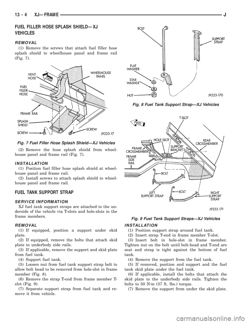
(1) Remove the screws that attach fuel filler hose
splash shield to wheelhouse panel and frame rail
(Fig. 7).
(2) Remove the hose splash shield from wheel-
house panel and frame rail (Fig. 7).
INSTALLATION
(1) Position fuel filler hose splash shield at wheel-
house panel and frame rail.
(2) Install screws to attach splash shield to wheel-
house panel and frame rail.
FUEL TANK SUPPORT STRAP
SERVICE INFORMATION
XJ fuel tank support straps are attached to the un-
derside of the vehicle via T-slots and hole-slots in the
frame members.
REMOVAL
(1) If equipped, position a support under skid
plate.
(2) If equipped, remove the bolts that attach skid
plate to underbody side rails.
(3) If applicable, remove the support and skid plate
from fuel tank.
(4) Support fuel tank.
(5) Loosen nut from fuel tank support strap bolt to
allow bolt head to be removed from hole-slot in frame
member (Fig. 8).
(6) Remove the strap T-end from frame member T-
slot (Fig. 9).
(7) Separate support strap from fuel tank and re-
move it from vehicle.
INSTALLATION
(1) Position support strap around fuel tank.
(2) Insert strap T-end in frame member T-slot.
(3) Insert bolt in hole-slot in frame member.
Tighten nut on the bolt until bolt-head and T-end are
seat and strap is tight against the bottom of fuel
tank.
(4) Remove the support from the fuel tank.
(5) If removed, position and support and the fuel
tank skid plate under the fuel tank.
(6) If applicable, install the bolts that attach the
skid plate to the underbody side rails. Tighten the
bolts to 50 Nzm (37 ft. lbs.) torque.
(7) Remove the support from under the skid plate.
Fig. 7 Fuel Filler Hose Splash ShieldÐXJ Vehicles
Fig. 8 Fuel Tank Support StrapÐXJ Vehicles
Fig. 9 Fuel Tank Support StrapsÐXJ Vehicles
13 - 4 XJÐFRAMEJ
Page 1419 of 2158
ACCELERATOR PEDAL AND THROTTLE CABLE
GENERAL INFORMATION
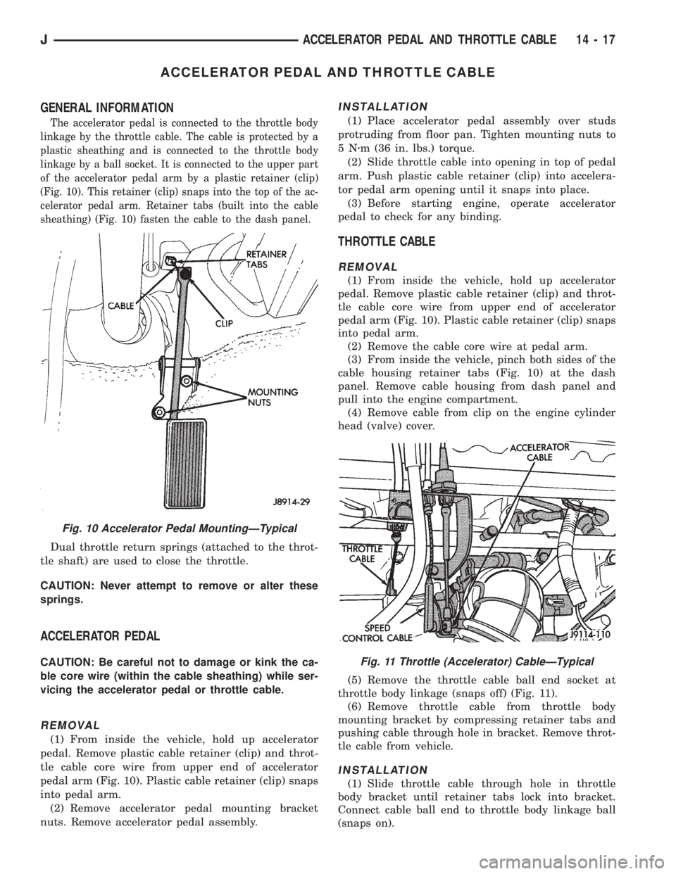
The accelerator pedal is connected to the throttle body
linkage by the throttle cable. The cable is protected by a
plastic sheathing and is connected to the throttle body
linkage by a ball socket. It is connected to the upper part
of the accelerator pedal arm by a plastic retainer (clip)
(Fig. 10). This retainer (clip) snaps into the top of the ac-
celerator pedal arm. Retainer tabs (built into the cable
sheathing) (Fig. 10) fasten the cable to the dash panel.
Dual throttle return springs (attached to the throt-
tle shaft) are used to close the throttle.
CAUTION: Never attempt to remove or alter these
springs.
ACCELERATOR PEDAL
CAUTION: Be careful not to damage or kink the ca-
ble core wire (within the cable sheathing) while ser-
vicing the accelerator pedal or throttle cable.
REMOVAL
(1) From inside the vehicle, hold up accelerator
pedal. Remove plastic cable retainer (clip) and throt-
tle cable core wire from upper end of accelerator
pedal arm (Fig. 10). Plastic cable retainer (clip) snaps
into pedal arm.
(2) Remove accelerator pedal mounting bracket
nuts. Remove accelerator pedal assembly.
INSTALLATION
(1) Place accelerator pedal assembly over studs
protruding from floor pan. Tighten mounting nuts to
5Nzm (36 in. lbs.) torque.
(2) Slide throttle cable into opening in top of pedal
arm. Push plastic cable retainer (clip) into accelera-
tor pedal arm opening until it snaps into place.
(3) Before starting engine, operate accelerator
pedal to check for any binding.
THROTTLE CABLE
REMOVAL
(1) From inside the vehicle, hold up accelerator
pedal. Remove plastic cable retainer (clip) and throt-
tle cable core wire from upper end of accelerator
pedal arm (Fig. 10). Plastic cable retainer (clip) snaps
into pedal arm.
(2) Remove the cable core wire at pedal arm.
(3) From inside the vehicle, pinch both sides of the
cable housing retainer tabs (Fig. 10) at the dash
panel. Remove cable housing from dash panel and
pull into the engine compartment.
(4) Remove cable from clip on the engine cylinder
head (valve) cover.
(5) Remove the throttle cable ball end socket at
throttle body linkage (snaps off) (Fig. 11).
(6) Remove throttle cable from throttle body
mounting bracket by compressing retainer tabs and
pushing cable through hole in bracket. Remove throt-
tle cable from vehicle.
INSTALLATION
(1) Slide throttle cable through hole in throttle
body bracket until retainer tabs lock into bracket.
Connect cable ball end to throttle body linkage ball
(snaps on).
Fig. 10 Accelerator Pedal MountingÐTypical
Fig. 11 Throttle (Accelerator) CableÐTypical
JACCELERATOR PEDAL AND THROTTLE CABLE 14 - 17
Page 1467 of 2158
INSTALLATION
(1) Install throttle body and new gasket. Tighten
throttle body mounting bolts to 12 Nzm (9 ft. lbs.)
torque.
(2) Connect idle air control motor and throttle po-
sition sensor wire connectors.
(3) Connect throttle linkage to throttle arm.
CAUTION: When the automatic transmission throttle
cable is connected, it MUST be adjusted.
(4) If equipped with an automatic transmission,
connect and adjust the transmission line pressure ca-
ble. Refer to Group 21, Transmissions for adjustment
procedure.
(5) Install air cleaner hose to throttle body.
(6) Connect negative battery cable to battery.
THROTTLE POSITION SENSOR (TPS)
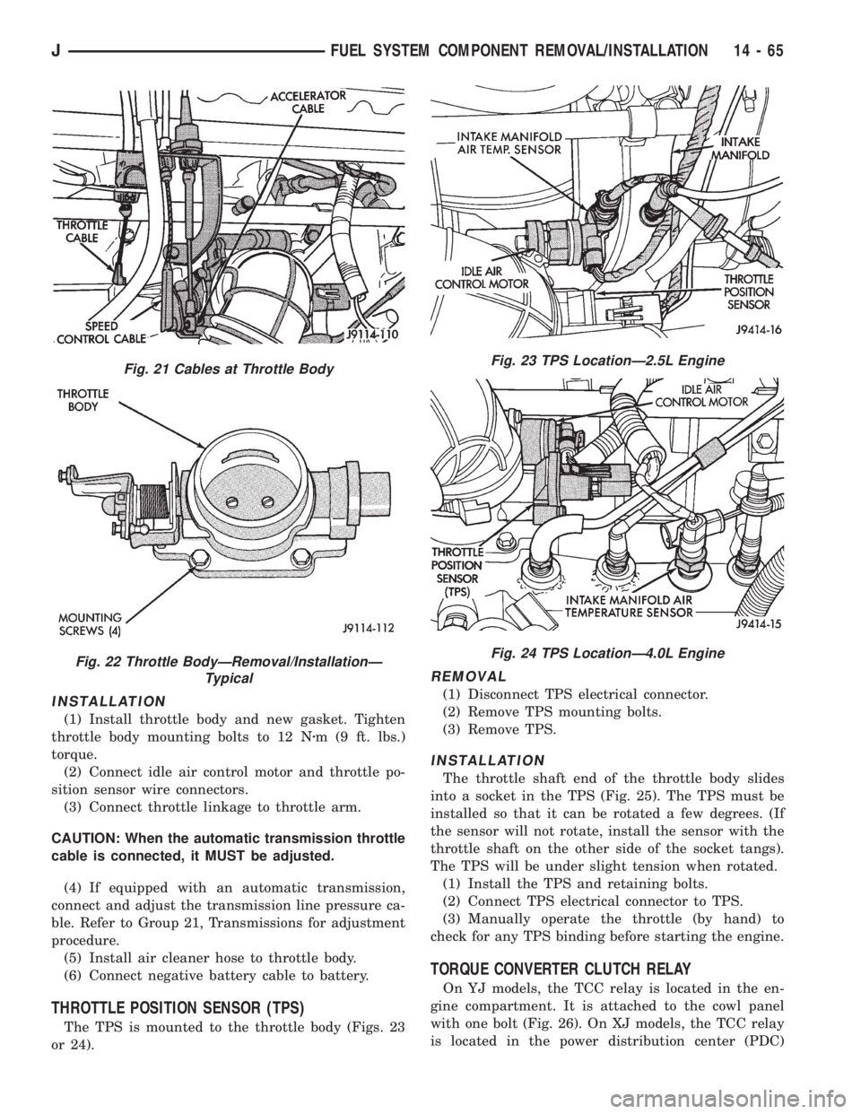
The TPS is mounted to the throttle body (Figs. 23
or 24).
REMOVAL
(1) Disconnect TPS electrical connector.
(2) Remove TPS mounting bolts.
(3) Remove TPS.
INSTALLATION
The throttle shaft end of the throttle body slides
into a socket in the TPS (Fig. 25). The TPS must be
installed so that it can be rotated a few degrees. (If
the sensor will not rotate, install the sensor with the
throttle shaft on the other side of the socket tangs).
The TPS will be under slight tension when rotated.
(1) Install the TPS and retaining bolts.
(2) Connect TPS electrical connector to TPS.
(3) Manually operate the throttle (by hand) to
check for any TPS binding before starting the engine.
TORQUE CONVERTER CLUTCH RELAY
On YJ models, the TCC relay is located in the en-
gine compartment. It is attached to the cowl panel
with one bolt (Fig. 26). On XJ models, the TCC relay
is located in the power distribution center (PDC)
Fig. 21 Cables at Throttle Body
Fig. 22 Throttle BodyÐRemoval/InstallationÐ
Typical
Fig. 23 TPS LocationÐ2.5L Engine
Fig. 24 TPS LocationÐ4.0L Engine
JFUEL SYSTEM COMPONENT REMOVAL/INSTALLATION 14 - 65
Page 1745 of 2158
(6) Let engine run at normal curb idle speed, apply
service brakes. Then shift transmission through all
gear ranges and back to PARK (leave engine run-
ning).
(7) Remove dipstick and check fluid level. Add only
enough fluid to bring level to Full mark on dipstick.
Do not overfill.If too much fluid is added, excess
amount can be removed with suction gun and
plastic tubing. Tubing only has to be long
enough to extend into oil pan.
(8) When fluid level is correct, shut engine off, re-
lease park brake, remove funnel, and reseat dipstick
in fill tube.
TRANSMISSION CONTROL MODULE (TCM)
SERVICE
Use the DRB scan tool to diagnose transmission
control module function whenever a fault is sus-
pected. Replace the module only when the scan tool
indicates the module is actually faulty.
TRANSMISSION CONTROL MODULE
REPLACEMENT
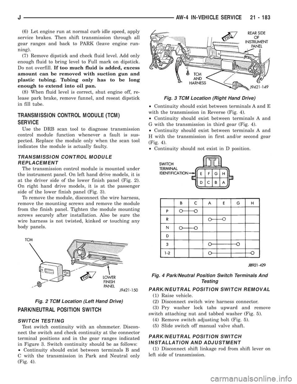
The transmission control module is mounted under
the instrument panel. On left hand drive models, it is
at the driver side of the lower finish panel (Fig. 2).
On right hand drive models, it is at the passenger
side of the lower finish panel (Fig. 3).
To remove the module, disconnect the wire harness,
remove the mounting screws and remove the module
from the finish panel. Tighten the module mounting
screws securely after installation. Also be sure the
wire harness is not twisted, kinked or touching any
body panels.
PARK/NEUTRAL POSITION SWITCH
SWITCH TESTING
Test switch continuity with an ohmmeter. Discon-
nect the switch and check continuity at the connector
terminal positions and in the gear ranges indicated
in Figure 3. Switch continuity should be as follows:
²Continuity should exist between terminals B and
C with the transmission in Park and Neutral only
(Fig. 4).²Continuity should exist between terminals A and E
with the transmission in Reverse (Fig. 4).
²Continuity should exist between terminals A and
G with the transmission in third gear (Fig. 4).
²Continuity should exist between terminals A and
H with the transmission in first and/or second gear
(Fig. 4).
²Continuity should not exist in D position.
PARK/NEUTRAL POSITION SWITCH REMOVAL
(1) Raise vehicle.
(2) Disconnect switch wire harness connector.
(3) Pry washer lock tabs upward and remove
switch attaching nut and tabbed washer (Fig. 5).
(4) Remove switch adjusting bolt (Fig. 5).
(5) Slide switch off manual valve shaft.
PARK/NEUTRAL POSITION SWITCH
INSTALLATION AND ADJUSTMENT
(1) Disconnect shift linkage rod from shift lever on
left side of transmission.
Fig. 2 TCM Location (Left Hand Drive)
Fig. 3 TCM Location (Right Hand Drive)
Fig. 4 Park/Neutral Position Switch Terminals And
Testing
JAW-4 IN-VEHICLE SERVICE 21 - 183