1995 JEEP YJ body panel emoval
[x] Cancel search: body panel emovalPage 2032 of 2158
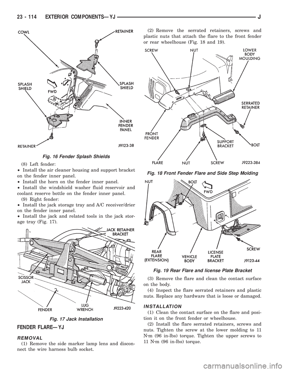
(8) Left fender:
²Install the air cleaner housing and support bracket
on the fender inner panel.
²Install the horn on the fender inner panel.
²Install the windshield washer fluid reservoir and
coolant reserve bottle on the fender inner panel.
(9) Right fender:
²Install the jack storage tray and A/C receiver/drier
on the fender inner panel.
²Install the jack and related tools in the jack stor-
age tray (Fig. 17).
FENDER FLAREÐYJ
REMOVAL
(1) Remove the side marker lamp lens and discon-
nect the wire harness bulb socket.(2) Remove the serrated retainers, screws and
plastic nuts that attach the flare to the front fender
or rear wheelhouse (Fig. 18 and 19).
(3) Remove the flare and clean the contact surface
on the body.
(4) Inspect the flare serrated retainers and plastic
nuts. Replace any hardware that is loose or damaged.
INSTALLATION
(1) Clean the contact surface on the flare and posi-
tion it on the front fender or wheelhouse.
(2) Install the flare serrated retainers, screws and
nuts. Tighten the screw at the lower molding to 11
Nzm (96 in-lbs) torque. Tighten the upper screws to
11 Nzm (96 in-lbs) torque.
Fig. 16 Fender Splash Shields
Fig. 17 Jack Installation
Fig. 18 Front Fender Flare and Side Step Molding
Fig. 19 Rear Flare and license Plate Bracket
23 - 114 EXTERIOR COMPONENTSÐYJJ
Page 2033 of 2158
BODY SIDE STEP MOLDINGÐYJ
REMOVAL/INSTALLATION
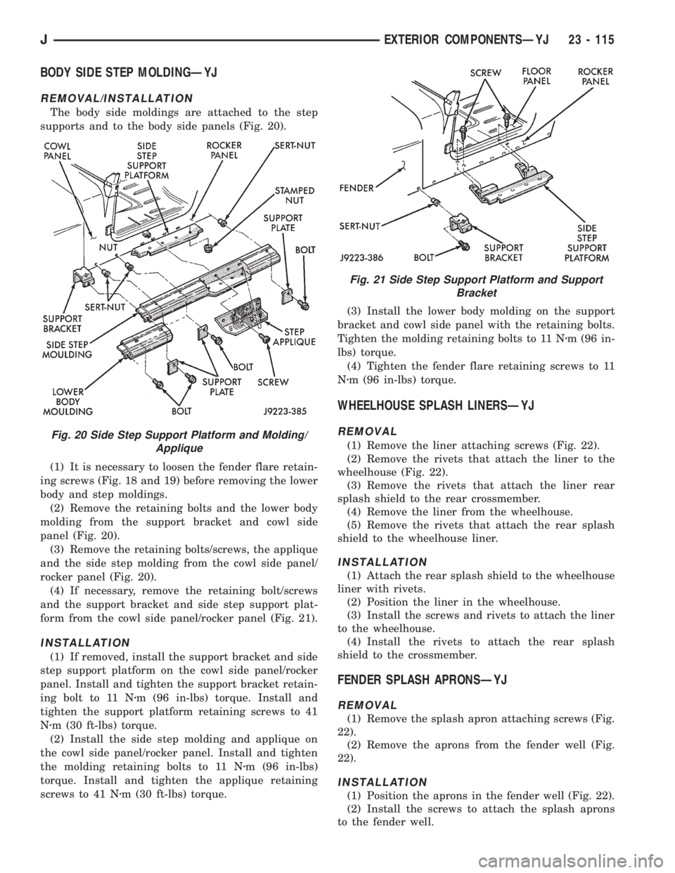
The body side moldings are attached to the step
supports and to the body side panels (Fig. 20).
(1) It is necessary to loosen the fender flare retain-
ing screws (Fig. 18 and 19) before removing the lower
body and step moldings.
(2) Remove the retaining bolts and the lower body
molding from the support bracket and cowl side
panel (Fig. 20).
(3) Remove the retaining bolts/screws, the applique
and the side step molding from the cowl side panel/
rocker panel (Fig. 20).
(4) If necessary, remove the retaining bolt/screws
and the support bracket and side step support plat-
form from the cowl side panel/rocker panel (Fig. 21).
INSTALLATION
(1) If removed, install the support bracket and side
step support platform on the cowl side panel/rocker
panel. Install and tighten the support bracket retain-
ing bolt to 11 Nzm (96 in-lbs) torque. Install and
tighten the support platform retaining screws to 41
Nzm (30 ft-lbs) torque.
(2) Install the side step molding and applique on
the cowl side panel/rocker panel. Install and tighten
the molding retaining bolts to 11 Nzm (96 in-lbs)
torque. Install and tighten the applique retaining
screws to 41 Nzm (30 ft-lbs) torque.(3) Install the lower body molding on the support
bracket and cowl side panel with the retaining bolts.
Tighten the molding retaining bolts to 11 Nzm (96 in-
lbs) torque.
(4) Tighten the fender flare retaining screws to 11
Nzm (96 in-lbs) torque.
WHEELHOUSE SPLASH LINERSÐYJ
REMOVAL
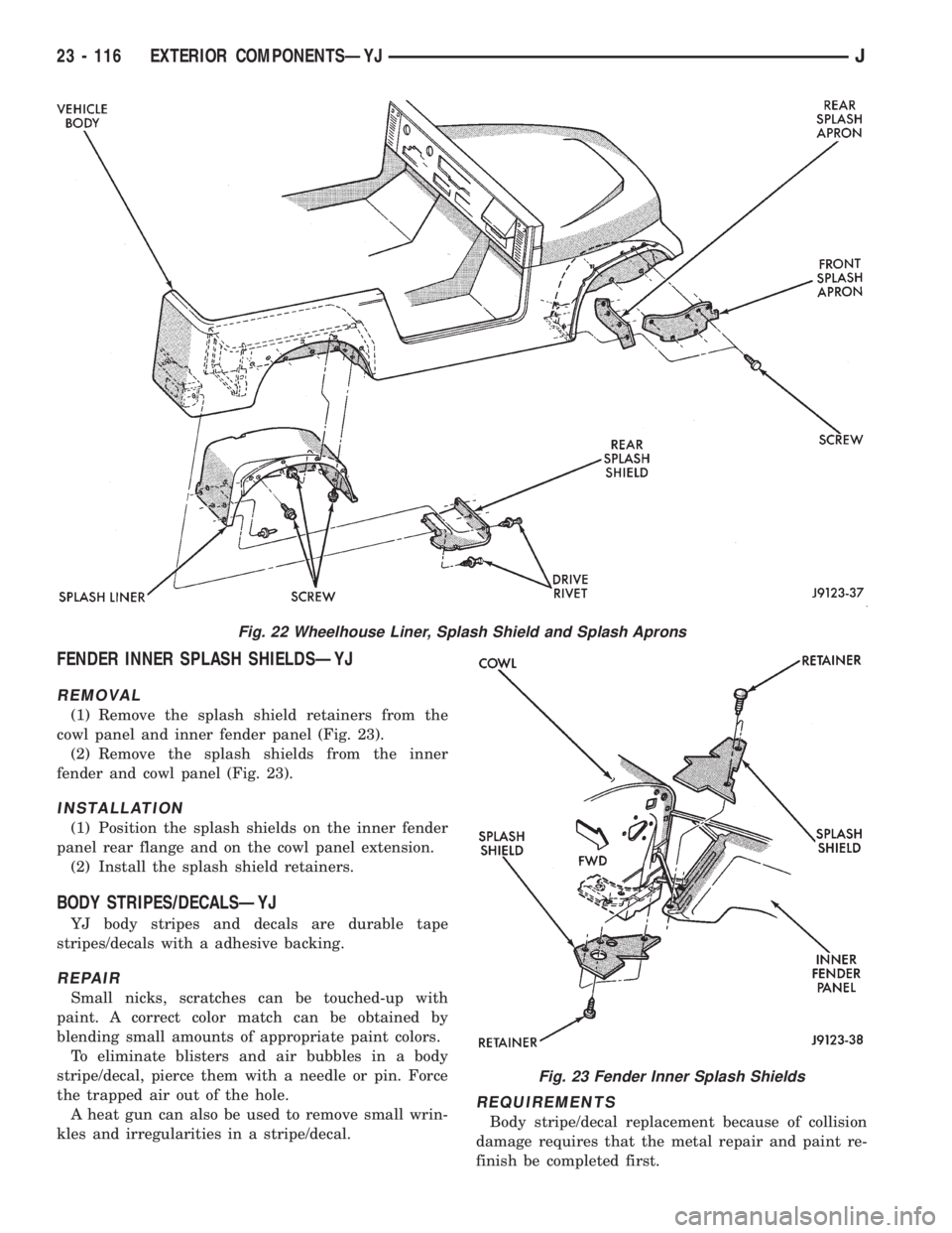
(1) Remove the liner attaching screws (Fig. 22).
(2) Remove the rivets that attach the liner to the
wheelhouse (Fig. 22).
(3) Remove the rivets that attach the liner rear
splash shield to the rear crossmember.
(4) Remove the liner from the wheelhouse.
(5) Remove the rivets that attach the rear splash
shield to the wheelhouse liner.
INSTALLATION
(1) Attach the rear splash shield to the wheelhouse
liner with rivets.
(2) Position the liner in the wheelhouse.
(3) Install the screws and rivets to attach the liner
to the wheelhouse.
(4) Install the rivets to attach the rear splash
shield to the crossmember.
FENDER SPLASH APRONSÐYJ
REMOVAL
(1) Remove the splash apron attaching screws (Fig.
22).
(2) Remove the aprons from the fender well (Fig.
22).
INSTALLATION
(1) Position the aprons in the fender well (Fig. 22).
(2) Install the screws to attach the splash aprons
to the fender well.
Fig. 20 Side Step Support Platform and Molding/
Applique
Fig. 21 Side Step Support Platform and Support
Bracket
JEXTERIOR COMPONENTSÐYJ 23 - 115
Page 2034 of 2158
FENDER INNER SPLASH SHIELDSÐYJ
REMOVAL
(1) Remove the splash shield retainers from the
cowl panel and inner fender panel (Fig. 23).
(2) Remove the splash shields from the inner
fender and cowl panel (Fig. 23).
INSTALLATION
(1) Position the splash shields on the inner fender
panel rear flange and on the cowl panel extension.
(2) Install the splash shield retainers.
BODY STRIPES/DECALSÐYJ
YJ body stripes and decals are durable tape
stripes/decals with a adhesive backing.
REPAIR
Small nicks, scratches can be touched-up with
paint. A correct color match can be obtained by
blending small amounts of appropriate paint colors.
To eliminate blisters and air bubbles in a body
stripe/decal, pierce them with a needle or pin. Force
the trapped air out of the hole.
A heat gun can also be used to remove small wrin-
kles and irregularities in a stripe/decal.
REQUIREMENTS
Body stripe/decal replacement because of collision
damage requires that the metal repair and paint re-
finish be completed first.
Fig. 22 Wheelhouse Liner, Splash Shield and Splash Aprons
Fig. 23 Fender Inner Splash Shields
23 - 116 EXTERIOR COMPONENTSÐYJJ
Page 2035 of 2158
The work area temperature should be between
18ÉC (65ÉF) and 32ÉC (90ÉF).A tape stripe/decal
should not be replaced if the work area temper-
ature is less than 18ÉC (65ÉF).
The following equipment and material are neces-
sary for body stripe/decal removal and installation:
²Commercial tape stripe/decal removal solution.
²Commercial adhesive removal solution.
²Liquid dish detergent (for the wetting solution).
²Mixture of wetting solution.
²Commercial wax and silicone removal solution.
²Isopropyl (rubbing) alcohol.
²Small squeegee (plastic or hard rubber).
²Water bucket and sponge.
²Clean wiping rags or paper towels.
²Heat gun (or infra-red heat bulb).
²Wax pencil.
²Sharp knife, single edge razor blade or X-acto
knife.
²Pair of scissors.
²Needle or pin.
A wetting solution assures a better bond between
the painted surface of the body and the tape stripe/
decal. Prepare a supply of wetting solution by mixing
two or three teaspoons of dish detergent with 1 gal-
lon of water.Do not use soap.
Too much detergent will reduce the effective-
ness of the mixture.
REMOVAL
The key to successful tape stripe/decal re-
moval is to apply heat to area and slowly peel
stripe/decal from panel.
(1) Clean the repaired surface, adjacent panels and
door openings as necessary.
(2) Start at one end of the tape stripe/decal and
apply heat with a heat gun. Slowly peel the stripe/
decal from the panel by pulling it back.Do not pull
the tape stripe/decal outward from the panel.
WARNING: USE THE TAPE STRIPE/DECAL RE-
MOVAL SOLUTION IN A WELL-VENTILATED AREA
ONLY.
(3) A commercial tape stripe/decal removal solution
can be used for stripe/decal removal at areas where a
heat gun is ineffective:
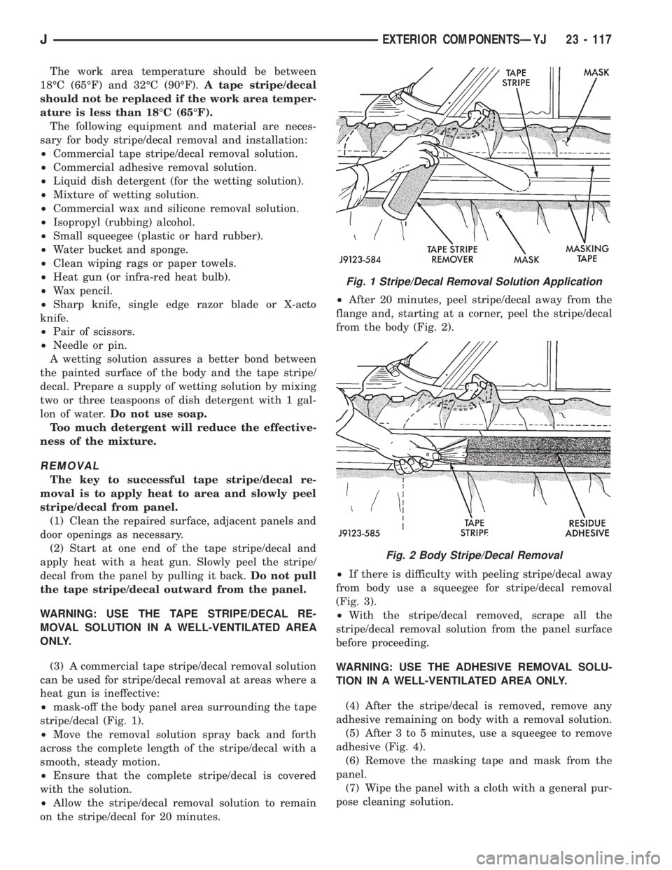
²mask-off the body panel area surrounding the tape
stripe/decal (Fig. 1).
²Move the removal solution spray back and forth
across the complete length of the stripe/decal with a
smooth, steady motion.
²Ensure that the complete stripe/decal is covered
with the solution.
²Allow the stripe/decal removal solution to remain
on the stripe/decal for 20 minutes.²After 20 minutes, peel stripe/decal away from the
flange and, starting at a corner, peel the stripe/decal
from the body (Fig. 2).
²If there is difficulty with peeling stripe/decal away
from body use a squeegee for stripe/decal removal
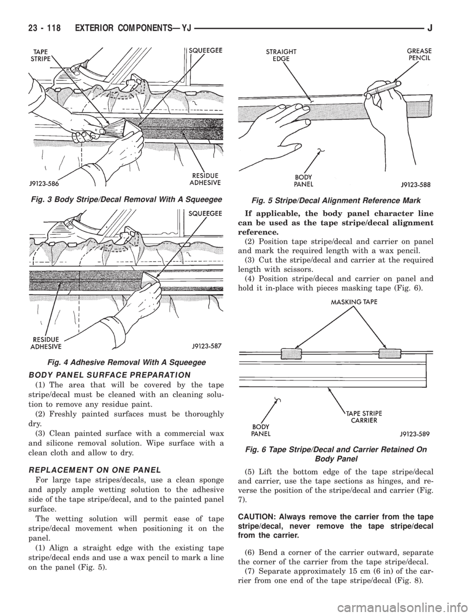
(Fig. 3).
²With the stripe/decal removed, scrape all the
stripe/decal removal solution from the panel surface
before proceeding.
WARNING: USE THE ADHESIVE REMOVAL SOLU-
TION IN A WELL-VENTILATED AREA ONLY.
(4) After the stripe/decal is removed, remove any
adhesive remaining on body with a removal solution.
(5) After 3 to 5 minutes, use a squeegee to remove
adhesive (Fig. 4).
(6) Remove the masking tape and mask from the
panel.
(7) Wipe the panel with a cloth with a general pur-
pose cleaning solution.
Fig. 1 Stripe/Decal Removal Solution Application
Fig. 2 Body Stripe/Decal Removal
JEXTERIOR COMPONENTSÐYJ 23 - 117
Page 2036 of 2158
BODY PANEL SURFACE PREPARATION
(1) The area that will be covered by the tape
stripe/decal must be cleaned with an cleaning solu-
tion to remove any residue paint.
(2) Freshly painted surfaces must be thoroughly
dry.
(3) Clean painted surface with a commercial wax
and silicone removal solution. Wipe surface with a
clean cloth and allow to dry.
REPLACEMENT ON ONE PANEL
For large tape stripes/decals, use a clean sponge
and apply ample wetting solution to the adhesive
side of the tape stripe/decal, and to the painted panel
surface.
The wetting solution will permit ease of tape
stripe/decal movement when positioning it on the
panel.
(1) Align a straight edge with the existing tape
stripe/decal ends and use a wax pencil to mark a line
on the panel (Fig. 5).If applicable, the body panel character line
can be used as the tape stripe/decal alignment
reference.
(2) Position tape stripe/decal and carrier on panel
and mark the required length with a wax pencil.
(3) Cut the stripe/decal and carrier at the required
length with scissors.
(4) Position stripe/decal and carrier on panel and
hold it in-place with pieces masking tape (Fig. 6).
(5) Lift the bottom edge of the tape stripe/decal
and carrier, use the tape sections as hinges, and re-
verse the position of the stripe/decal and carrier (Fig.
7).
CAUTION: Always remove the carrier from the tape
stripe/decal, never remove the tape stripe/decal
from the carrier.
(6) Bend a corner of the carrier outward, separate
the corner of the carrier from the tape stripe/decal.
(7) Separate approximately 15 cm (6 in) of the car-
rier from one end of the tape stripe/decal (Fig. 8).
Fig. 3 Body Stripe/Decal Removal With A Squeegee
Fig. 4 Adhesive Removal With A Squeegee
Fig. 5 Stripe/Decal Alignment Reference Mark
Fig. 6 Tape Stripe/Decal and Carrier Retained On
Body Panel
23 - 118 EXTERIOR COMPONENTSÐYJJ
Page 2038 of 2158
painted panel surface. The solution will permit ease
of tape stripe/decal movement when positioning it on
the panel.
(5) Position adhesive-coated side of tape stripe/de-
cal on the panel with the bottom aligned with char-
acter line. Where applicable:
²align the end of the replacement tape stripe/decal
with the end of the existing tape stripe/decal, and
correctly align the index darts and index notches.
(6) If a complete replacement tape stripe/decal is
not being installed:
²Position the replacement tape stripe/decal section
at the center of the repair area.
²Align it with the existing tape stripe/decal and al-
low at least 12 mm (1/2 in) of the tape stripe/decal
section to overlap the existing tape stripe/decal
edges.(7) Apply wetting solution to the outer side of the
tape stripe/decal to allow the squeegee to freely slide
while adhering the stripe/decal to the panel.
CAUTION: Avoid unnecessary pulling and stretch-
ing at the ends of the tape stripe/decal because this
could cause it to tear.
(8) Position and slide a squeegee from the center to
the ends of the tape stripe/decal. This will ensure
complete bonding of the tape stripe/decal to the
painted panel surface.
(9) If a wrinkle is trapped in the tape stripe/decal
during the squeegee operation, stop. Lift wrinkled
area and re-align stripe/decal with panel character
line.Do not lift the tape stripe/decal if only a
few air bubbles exist.
(10) Where applicable, allow 12 mm (1/2 in) extra
tape stripe/decal to extend beyond the edges to be
folded over.
(11) Fold the excess tape stripe/decal back onto in-
side flange area.Use care to avoid trapping air
under the tape stripe/decal.Where necessary, trim
excess tape stripe/decal.
(12) Inspect tape installation with reflected light to
detect any defects that could have developed during
the installation.
(13) Remove all air and moisture bubbles from the
tape stripe/decal with a needle or pin.
(14) Install any removed components and clean the
vehicle as necessary.
EXTERIOR NAMEPLATES (ADHESIVE-BACKED)ÐYJ
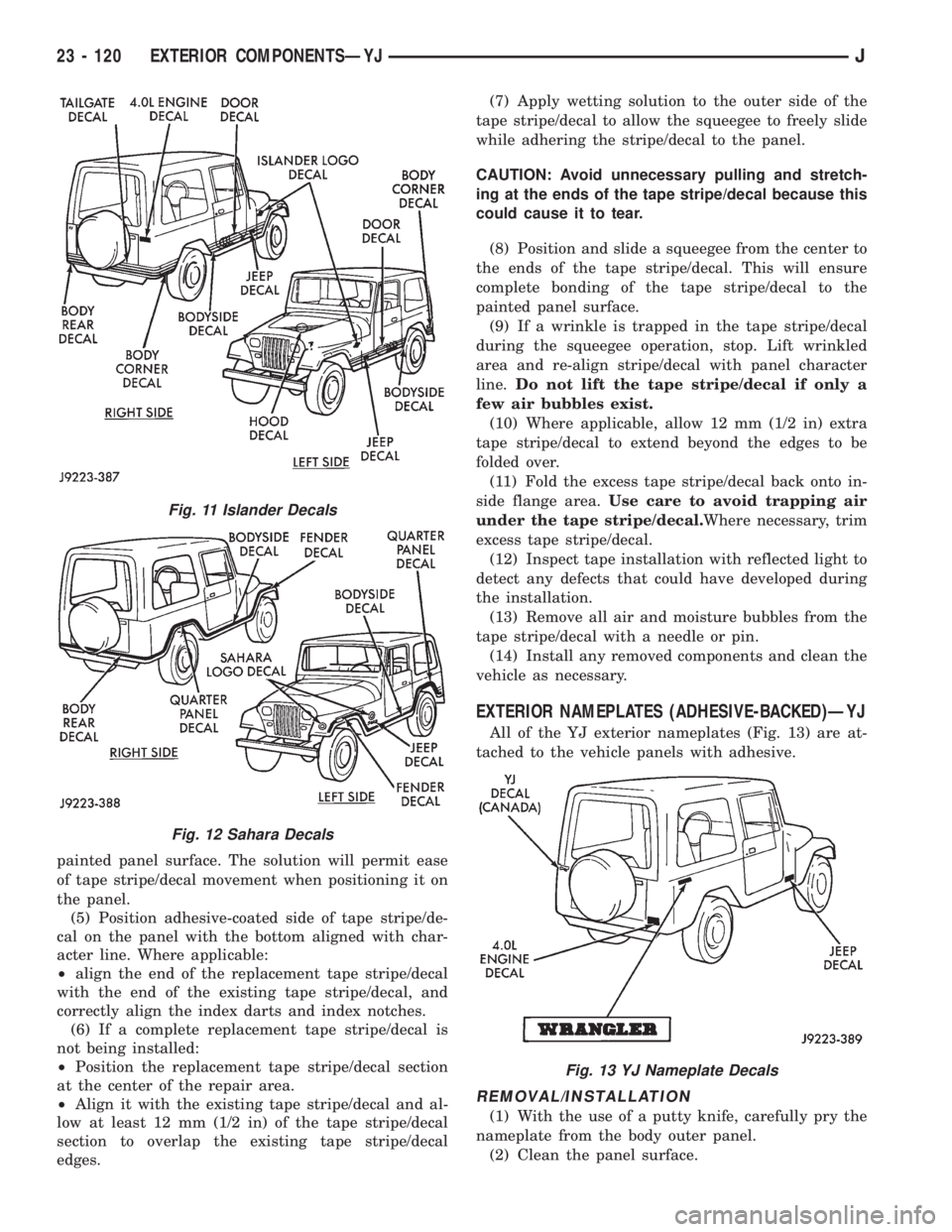
All of the YJ exterior nameplates (Fig. 13) are at-
tached to the vehicle panels with adhesive.
REMOVAL/INSTALLATION
(1) With the use of a putty knife, carefully pry the
nameplate from the body outer panel.
(2) Clean the panel surface.
Fig. 11 Islander Decals
Fig. 12 Sahara Decals
Fig. 13 YJ Nameplate Decals
23 - 120 EXTERIOR COMPONENTSÐYJJ
Page 2039 of 2158
(3) Position the replacement nameplate on the
panel and apply inward force to seat it.
FUEL FILLER PROTECTOR/NOZZLEÐYJ
REMOVAL
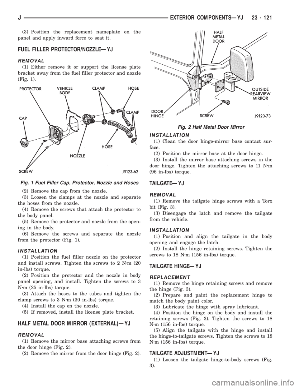
(1) Either remove it or support the license plate
bracket away from the fuel filler protector and nozzle
(Fig. 1).
(2) Remove the cap from the nozzle.
(3) Loosen the clamps at the nozzle and separate
the hoses from the nozzle.
(4) Remove the screws that attach the protector to
the body panel.
(5) Remove the protector and nozzle from the open-
ing in the body.
(6) Remove the screws and separate the nozzle
from the protector (Fig. 1).
INSTALLATION
(1) Position the fuel filler nozzle on the protector
and install screws. Tighten the screws to 2 Nzm (20
in-lbs) torque.
(2) Position the protector and the nozzle in body
panel opening, and install. Tighten the screws to 3
Nzm (25 in-lbs) torque.
(3) Attach the hoses to the tubes and tighten the
clamp screws to 3 Nzm (30 in-lbs) torque.
(4) Install the cap on the nozzle.
(5) If removed, install the license plate bracket.
HALF METAL DOOR MIRROR (EXTERNAL)ÐYJ
REMOVAL
(1) Remove the mirror base attaching screws from
the door hinge (Fig. 2).
(2) Remove the mirror from the door hinge (Fig. 2).
INSTALLATION
(1) Clean the door hinge-mirror base contact sur-
face.
(2) Position the mirror base at the door hinge.
(3) Install the mirror base attaching screws in the
door hinge. Tighten the attaching screws to 11 Nzm
(96 in-lbs) torque.
TAILGATEÐYJ
REMOVAL
(1) Remove the tailgate hinge screws with a Torx
bit (Fig. 3).
(3) Disengage the latch and remove the tailgate
from the vehicle.
INSTALLATION
(1) Position and align the tailgate in the body
opening and engage the latch.
(2) Install the hinge retaining screws. Tighten the
screws to 18 Nzm (156 in-lbs) torque.
TAILGATE HINGEÐYJ
REPLACEMENT
(1) Remove the hinge retaining screws and remove
the hinge (Fig. 3).
(2) Prepare and paint the replacement hinge to
match the body paint color.
(3) Lubricate the hinge with spray lubricant.
(4) Position the hinge on the body and install the
retaining screws (Fig. 3). Tighten the screws to 18
Nzm (156 in-lbs) torque.
(5) Align the tailgate with the hinge and install
the hinge-to-tailgate screws. Tighten the screws to 18
Nzm (156 in-lbs) torque.
TAILGATE ADJUSTMENTÐYJ
(1) Loosen the tailgate hinge-to-body screws (Fig.
3).
Fig. 1 Fuel Filler Cap, Protector, Nozzle and Hoses
Fig. 2 Half Metal Door Mirror
JEXTERIOR COMPONENTSÐYJ 23 - 121
Page 2043 of 2158
(8) Separate the liftgate glass from the hard top.
(9) Remove the weatherstrip seal (Fig. 2), if neces-
sary.
INSTALLATION
(1) Assemble the liftgate components, if necessary
(2) Position the liftgate glass in the hard top open-
ing and install the hinge bolts. Do not tighten the
bolts.
(3) Adjust the liftgate glass to fit the hard top
opening.
(4) Tighten the hinge bolts to 11 Nzm (95 in-lbs)
torque.
(5) Position the support rod cylinders on the ball
studs.
(6) Install the support rod cylinder retainer clips.
(7) Connect the wiper motor wire harness connec-
tor and the washer fluid hose. Install the wiper mo-
tor cover (Fig. 1).
(8) Install the wiper arm and blade.
(9) Connect the rear window defroster/dome lamp
wire harness connectors.
DISASSEMBLY
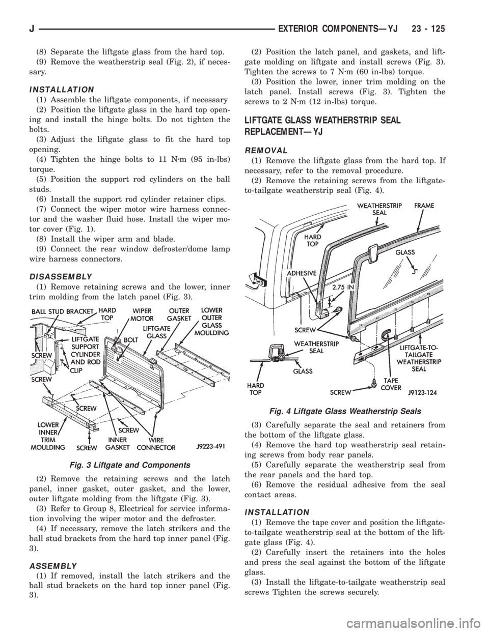
(1) Remove retaining screws and the lower, inner
trim molding from the latch panel (Fig. 3).
(2) Remove the retaining screws and the latch
panel, inner gasket, outer gasket, and the lower,
outer liftgate molding from the liftgate (Fig. 3).
(3) Refer to Group 8, Electrical for service informa-
tion involving the wiper motor and the defroster.
(4) If necessary, remove the latch strikers and the
ball stud brackets from the hard top inner panel (Fig.
3).
ASSEMBLY
(1) If removed, install the latch strikers and the
ball stud brackets on the hard top inner panel (Fig.
3).(2) Position the latch panel, and gaskets, and lift-
gate molding on liftgate and install screws (Fig. 3).
Tighten the screws to 7 Nzm (60 in-lbs) torque.
(3) Position the lower, inner trim molding on the
latch panel. Install screws (Fig. 3). Tighten the
screws to 2 Nzm (12 in-lbs) torque.
LIFTGATE GLASS WEATHERSTRIP SEAL
REPLACEMENTÐYJ
REMOVAL
(1) Remove the liftgate glass from the hard top. If
necessary, refer to the removal procedure.
(2) Remove the retaining screws from the liftgate-
to-tailgate weatherstrip seal (Fig. 4).
(3) Carefully separate the seal and retainers from
the bottom of the liftgate glass.
(4) Remove the hard top weatherstrip seal retain-
ing screws from body rear panels.
(5) Carefully separate the weatherstrip seal from
the rear panels and the hard top.
(6) Remove the residual adhesive from the seal
contact areas.
INSTALLATION
(1) Remove the tape cover and position the liftgate-
to-tailgate weatherstrip seal at the bottom of the lift-
gate glass (Fig. 4).
(2) Carefully insert the retainers into the holes
and press the seal against the bottom of the liftgate
glass.
(3) Install the liftgate-to-tailgate weatherstrip seal
screws Tighten the screws securely.
Fig. 3 Liftgate and Components
Fig. 4 Liftgate Glass Weatherstrip Seals
JEXTERIOR COMPONENTSÐYJ 23 - 125