1995 JEEP YJ wiring
[x] Cancel search: wiringPage 1441 of 2158
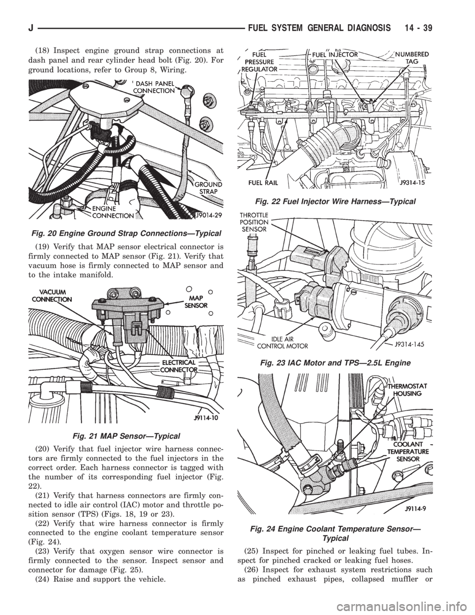
(18) Inspect engine ground strap connections at
dash panel and rear cylinder head bolt (Fig. 20). For
ground locations, refer to Group 8, Wiring.
(19) Verify that MAP sensor electrical connector is
firmly connected to MAP sensor (Fig. 21). Verify that
vacuum hose is firmly connected to MAP sensor and
to the intake manifold.
(20) Verify that fuel injector wire harness connec-
tors are firmly connected to the fuel injectors in the
correct order. Each harness connector is tagged with
the number of its corresponding fuel injector (Fig.
22).
(21) Verify that harness connectors are firmly con-
nected to idle air control (IAC) motor and throttle po-
sition sensor (TPS) (Figs. 18, 19 or 23).
(22) Verify that wire harness connector is firmly
connected to the engine coolant temperature sensor
(Fig. 24).
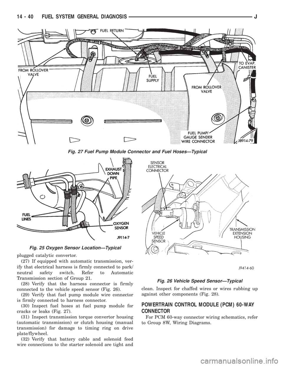
(23) Verify that oxygen sensor wire connector is
firmly connected to the sensor. Inspect sensor and
connector for damage (Fig. 25).
(24) Raise and support the vehicle.(25) Inspect for pinched or leaking fuel tubes. In-
spect for pinched cracked or leaking fuel hoses.
(26) Inspect for exhaust system restrictions such
as pinched exhaust pipes, collapsed muffler or
Fig. 20 Engine Ground Strap ConnectionsÐTypical
Fig. 21 MAP SensorÐTypical
Fig. 22 Fuel Injector Wire HarnessÐTypical
Fig. 23 IAC Motor and TPSÐ2.5L Engine
Fig. 24 Engine Coolant Temperature SensorÐ
Typical
JFUEL SYSTEM GENERAL DIAGNOSIS 14 - 39
Page 1442 of 2158
plugged catalytic convertor.
(27) If equipped with automatic transmission, ver-
ify that electrical harness is firmly connected to park/
neutral safety switch. Refer to Automatic
Transmission section of Group 21.
(28) Verify that the harness connector is firmly
connected to the vehicle speed sensor (Fig. 26).
(29) Verify that fuel pump module wire connector
is firmly connected to harness connector.
(30) Inspect fuel hoses at fuel pump module for
cracks or leaks (Fig. 27).
(31) Inspect transmission torque convertor housing
(automatic transmission) or clutch housing (manual
transmission) for damage to timing ring on drive
plate/flywheel.
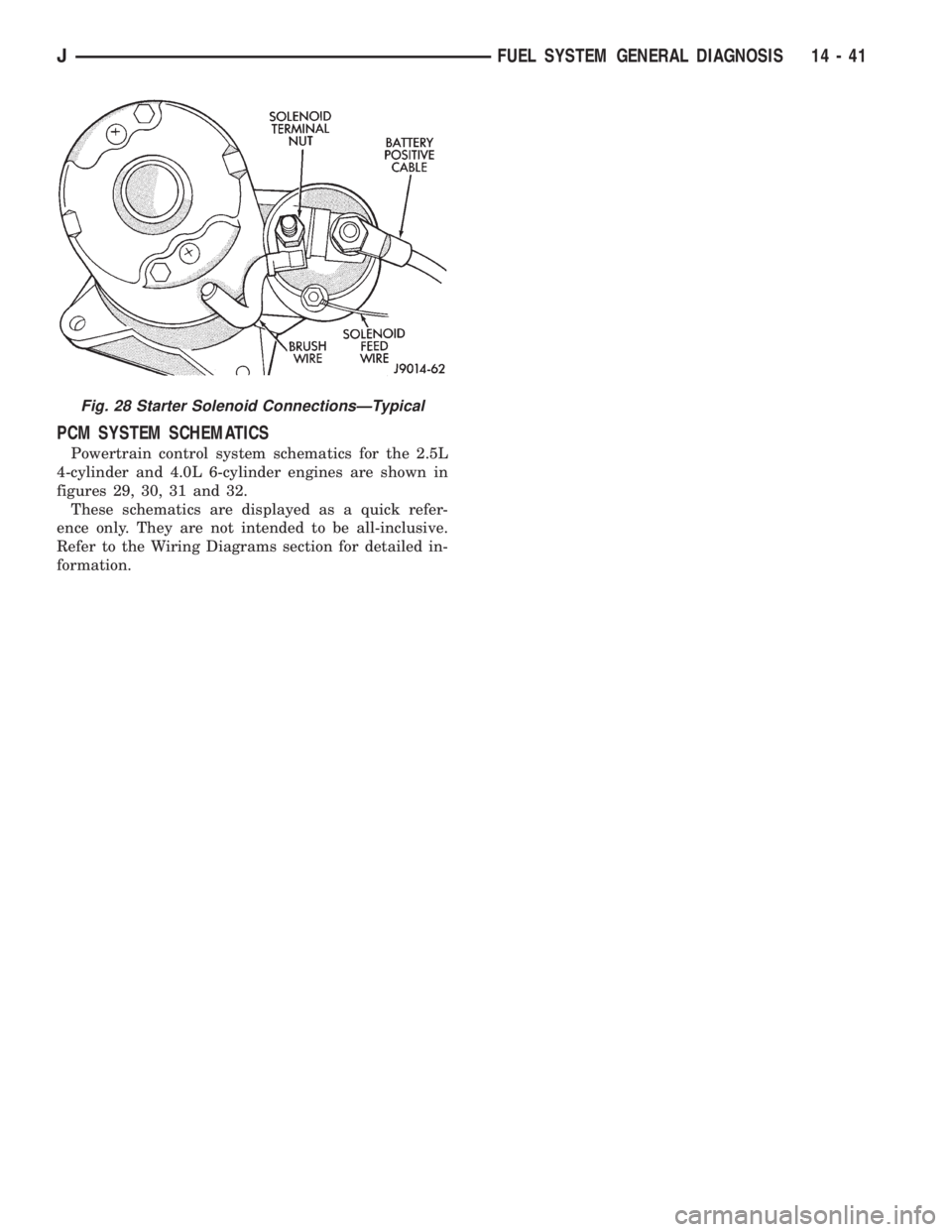
(32) Verify that battery cable and solenoid feed
wire connections to the starter solenoid are tight andclean. Inspect for chaffed wires or wires rubbing up
against other components (Fig. 28).
POWERTRAIN CONTROL MODULE (PCM) 60-WAY
CONNECTOR
For PCM 60-way connector wiring schematics, refer
to Group 8W, Wiring Diagrams.
Fig. 27 Fuel Pump Module Connector and Fuel HosesÐTypical
Fig. 25 Oxygen Sensor LocationÐTypical
Fig. 26 Vehicle Speed SensorÐTypical
14 - 40 FUEL SYSTEM GENERAL DIAGNOSISJ
Page 1443 of 2158
PCM SYSTEM SCHEMATICS
Powertrain control system schematics for the 2.5L
4-cylinder and 4.0L 6-cylinder engines are shown in
figures 29, 30, 31 and 32.
These schematics are displayed as a quick refer-
ence only. They are not intended to be all-inclusive.
Refer to the Wiring Diagrams section for detailed in-
formation.
Fig. 28 Starter Solenoid ConnectionsÐTypical
JFUEL SYSTEM GENERAL DIAGNOSIS 14 - 41
Page 1449 of 2158
Test the resistance of the wire harness. Do this be-
tween the powertrain control module (PCM) wire
harness connector terminal-2 and the sensor connec-
tor terminal. Also test terminal-4 to the sensor con-
nector terminal. Repair the wire harness as
necessary if the resistance is greater than 1 ohm.
FUEL PUMP RELAY TESTING
For testing this relay, refer to RelaysÐOperation/
Testing in this section of the group.
MANIFOLD ABSOLUTE PRESSURE (MAP) SENSOR
TEST
To perform a complete test of the MAP sensor and
its circuitry, refer to DRB scan tool and appropriate
Powertrain Diagnostics Procedures manual. To test
the sensor only, refer to the following:
Inspect the MAP sensor vacuum hose connections
at the throttle body and sensor. Repair as necessary.
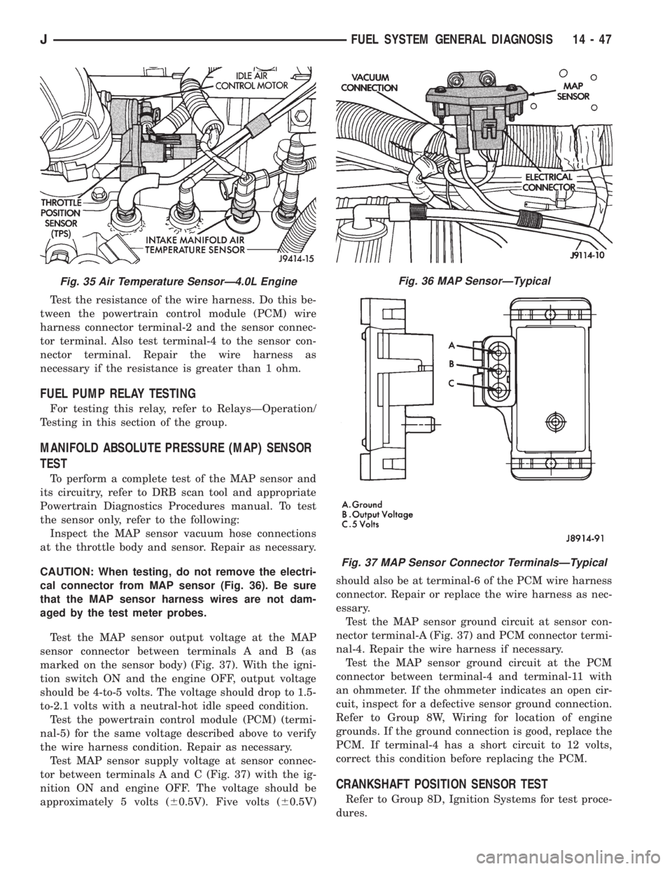
CAUTION: When testing, do not remove the electri-
cal connector from MAP sensor (Fig. 36). Be sure
that the MAP sensor harness wires are not dam-
aged by the test meter probes.
Test the MAP sensor output voltage at the MAP
sensor connector between terminals A and B (as
marked on the sensor body) (Fig. 37). With the igni-
tion switch ON and the engine OFF, output voltage
should be 4-to-5 volts. The voltage should drop to 1.5-
to-2.1 volts with a neutral-hot idle speed condition.
Test the powertrain control module (PCM) (termi-
nal-5) for the same voltage described above to verify
the wire harness condition. Repair as necessary.
Test MAP sensor supply voltage at sensor connec-
tor between terminals A and C (Fig. 37) with the ig-
nition ON and engine OFF. The voltage should be
approximately 5 volts (60.5V). Five volts (60.5V)should also be at terminal-6 of the PCM wire harness
connector. Repair or replace the wire harness as nec-
essary.
Test the MAP sensor ground circuit at sensor con-
nector terminal-A (Fig. 37) and PCM connector termi-
nal-4. Repair the wire harness if necessary.
Test the MAP sensor ground circuit at the PCM
connector between terminal-4 and terminal-11 with
an ohmmeter. If the ohmmeter indicates an open cir-
cuit, inspect for a defective sensor ground connection.
Refer to Group 8W, Wiring for location of engine
grounds. If the ground connection is good, replace the
PCM. If terminal-4 has a short circuit to 12 volts,
correct this condition before replacing the PCM.
CRANKSHAFT POSITION SENSOR TEST
Refer to Group 8D, Ignition Systems for test proce-
dures.
Fig. 35 Air Temperature SensorÐ4.0L EngineFig. 36 MAP SensorÐTypical
Fig. 37 MAP Sensor Connector TerminalsÐTypical
JFUEL SYSTEM GENERAL DIAGNOSIS 14 - 47
Page 1450 of 2158
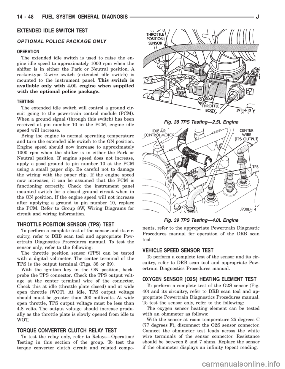
EXTENDED IDLE SWITCH TEST
OPTIONAL POLICE PACKAGE ONLY
OPERATION
The extended idle switch is used to raise the en-
gine idle speed to approximately 1000 rpm when the
shifter is in either the Park or Neutral position. A
rocker-type 2-wire switch (extended idle switch) is
mounted to the instrument panel.This switch is
available only with 4.0L engine when supplied
with the optional police package.
TESTING
The extended idle switch will control a ground cir-
cuit going to the powertrain control module (PCM).
When a ground signal (through this switch) has been
received at pin number 10 in the PCM, engine idle
speed will increase.
Bring the engine to normal operating temperature
and turn the extended idle switch to the ON position.
Engine speed should now increase to approximately
1000 rpm when the shifter is in either the Park or
Neutral position. If engine speed does not increase,
apply a good ground to pin number 10 at the PCM
using a small paper clip. Be careful not to damage
the wiring with the paper clip. If the engine speed
now increases, it can be assumed that the PCM is
functioning correctly. Check the instrument panel
mounted switch for a closed ground circuit when in
the ON position. If the engine speed will not increase
after applying a ground to pin number 10, replace
the PCM. Refer to Group 8W, Wiring Diagrams for
circuit and wiring information.
THROTTLE POSITION SENSOR (TPS) TEST
To perform a complete test of the sensor and its cir-
cuitry, refer to DRB scan tool and appropriate Pow-
ertrain Diagnostics Procedures manual. To test the
sensor only, refer to the following:
The throttle position sensor (TPS) can be tested
with a digital voltmeter. The center terminal of the
TPS is the output terminal (Figs. 38 or 39).
With the ignition key in the ON position, back-
probe the TPS connector. Check the TPS output volt-
age at the center terminal wire of the connector.
Check this at idle (throttle plate closed) and at wide
open throttle (WOT). At idle, TPS output voltage
should must be greater than 200 millivolts. At wide
open throttle, TPS output voltage must be less than
4.8 volts. The output voltage should increase gradu-
ally as the throttle plate is slowly opened from idle to
WOT.
TORQUE CONVERTER CLUTCH RELAY TEST
To test the relay only, refer to RelaysÐOperation/
Testing in this section of the group. To test the
torque converter clutch circuit and related compo-nents, refer to the appropriate Powertrain Diagnostic
Procedures manual for operation of the DRB scan
tool.
VEHICLE SPEED SENSOR TEST
To perform a complete test of the sensor and its cir-
cuitry, refer to DRB scan tool and appropriate Pow-
ertrain Diagnostics Procedures manual.
OXYGEN SENSOR (O2S) HEATING ELEMENT TEST
To perform a complete test of the O2S sensor (Fig.
40) and its circuitry, refer to DRB scan tool and ap-
propriate Powertrain Diagnostics Procedures manual.
To test the sensor only, refer to the following:
The oxygen sensor heating element can be tested
with an ohmmeter as follows:
With the sensor at room temperature 25 degrees C
(77 degrees F), disconnect the O2S sensor connector.
Connect the ohmmeter test leads across the white
wire terminals of the sensor connector. Resistance
should be between 5 and 7 ohms. Replace the sensor
if the ohmmeter displays an infinity (open) reading.
Fig. 38 TPS TestingÐ2.5L Engine
Fig. 39 TPS TestingÐ4.0L Engine
14 - 48 FUEL SYSTEM GENERAL DIAGNOSISJ
Page 1453 of 2158
(8) Disconnect jumper wires from relay and 12 Volt
power source.
If continuity or resistance tests did not pass, re-
place relay. If tests passed, refer to Group 8W, Wiring
Diagrams for additional circuit information. Also re-
fer to the appropriate Powertrain Diagnostic Proce-
dures manual for operation of the DRB scan tool.
STARTER MOTOR RELAY TEST
Refer to Group 8A, Battery/Starting/Charging/Sys-
tem Diagnostics, for starter motor relay testing.
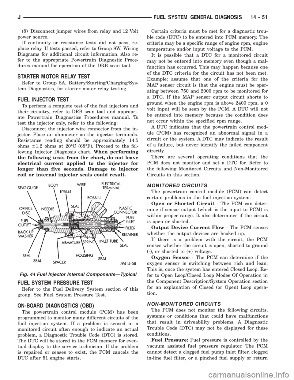
FUEL INJECTOR TEST
To perform a complete test of the fuel injectors and
their circuitry, refer to DRB scan tool and appropri-
ate Powertrain Diagnostics Procedures manual. To
test the injector only, refer to the following:
Disconnect the injector wire connector from the in-
jector. Place an ohmmeter on the injector terminals.
Resistance reading should be approximately 14.5
ohms61.2 ohms at 20ÉC (68ÉF). Proceed to the fol-
lowing Injector Diagnosis chart.When performing
the following tests from the chart, do not leave
electrical current applied to the injector for
longer than five seconds. Damage to injector
coil or internal injector seals could result.
FUEL SYSTEM PRESSURE TEST
Refer to the Fuel Delivery System section of this
group. See Fuel System Pressure Test.
ON-BOARD DIAGNOSTICS (OBD)
The powertrain control module (PCM) has been
programmed to monitor many different circuits of the
fuel injection system. If a problem is sensed in a
monitored circuit often enough to indicate an actual
problem, a Diagnostic Trouble Code (DTC) is stored.
The DTC will be stored in the PCM memory for even-
tual display to the service technician. If the problem
is repaired or ceases to exist, the PCM cancels the
DTC after 51 engine starts.Certain criteria must be met for a diagnostic trou-
ble code (DTC) to be entered into PCM memory. The
criteria may be a specific range of engine rpm, engine
temperature and/or input voltage to the PCM.
It is possible that a DTC for a monitored circuit
may not be entered into memory even though a mal-
function has occurred. This may happen because one
of the DTC criteria for the circuit has not been met.
Example: assume that one of the criteria for the
MAP sensor circuit is that the engine must be oper-
ating between 750 and 2000 rpm to be monitored for
a DTC. If the MAP sensor output circuit shorts to
ground when the engine rpm is above 2400 rpm, a 0
volt input will be seen by the PCM. A DTC will not
be entered into memory because the condition does
not occur within the specified rpm range.
A DTC indicates that the powertrain control mod-
ule (PCM) has recognized an abnormal signal in a
circuit or the system. A DTC may indicate the result
of a failure, but never identify the failed component
directly.
There are several operating conditions that the
PCM does not monitor and set a DTC for. Refer to
the following Monitored Circuits and Non-Monitored
Circuits in this section.
MONITORED CIRCUITS
The powertrain control module (PCM) can detect
certain problems in the fuel injection system.
Open or Shorted Circuit- The PCM can deter-
mine if sensor output (which is the input to PCM) is
within proper range. It also determines if the circuit
is open or shorted.
Output Device Current Flow- The PCM senses
whether the output devices are hooked up.
If there is a problem with the circuit, the PCM
senses whether the circuit is open, shorted to ground
(-), or shorted to (+) voltage.
Oxygen Sensor- The PCM can determine if the
oxygen sensor is switching between rich and lean.
This is, once the system has entered Closed Loop. Re-
fer to Open Loop/Closed Loop Modes Of Operation in
the Component Description/System Operation section
for an explanation of Closed (or Open) Loop opera-
tion.
NON-MONITORED CIRCUITS
The PCM does not monitor the following circuits,
systems or conditions that could have malfunctions
that result in driveability problems. A Diagnostic
Trouble Code (DTC) may not be displayed for these
conditions.
Fuel Pressure:Fuel pressure is controlled by the
vacuum assisted fuel pressure regulator. The PCM
cannot detect a clogged fuel pump inlet filter, clogged
in-line fuel filter, or a pinched fuel supply or return
Fig. 44 Fuel Injector Internal ComponentsÐTypical
JFUEL SYSTEM GENERAL DIAGNOSIS 14 - 51
Page 1532 of 2158
GENERAL INFORMATION
The airbag system is a standard equipment safety
device on XJ (Cherokee) models. It is designed to pro-
tect the driver from serious injury, caused by a fron-
tal impact of the vehicle. If the airbag module
assembly is defective and non-deployed, refer to
Chrysler Corporation current return list for proper
handling procedures.
ARMING/DISARMING MECHANISM
BEFORE SERVICING A COLUMN EQUIPPED
WITH AIR BAG, REFER TO GROUP 8M, ELEC-
TRICAL FOR PROPER AND SAFE PROCE-
DURES.
The steering wheel hub incorporates an airbag
Arming/Disarming mechanism and a specially de-
signed nut-blocker. The nut-blocker serves as a safety
to prevent removal of the airbag module until the
unit has been disarmed. A removable plastic cover
plug on the top, outer hub of the steering wheel al-
lows access to the arming screw.
When the airbag module is disarmed, the arming
screw extends upward from the steering wheel hub.
This will prevent installation of the plastic cover
plug. Also, the nut-blocker is retracted to allow ac-
cess to the two upper airbag module mounting nuts.
When the airbag module is armed, the plastic cover
plug will install flush with the outer surface of the
steering wheel hub. In addition, the nut-blocker will
prevent access to the two upper airbag module
mounting nuts.THE FASTENERS, SCREWS, AND BOLTS, ORIG-
INALLY USED FOR THE AIR BAG COMPONENTS,
HAVE SPECIAL COATINGS. THIS HARDWARE IS
SPECIFICALLY DESIGNED FOR THE AIR BAG
SYSTEM. THEY MUST NEVER BE REPLACED
WITH ANY SUBSTITUTES. REPLACE WITH THE
CORRECT FASTENERS PROVIDED IN THE SER-
VICE PACKAGE OR FASTENERS IN THE PARTS
BOOK.
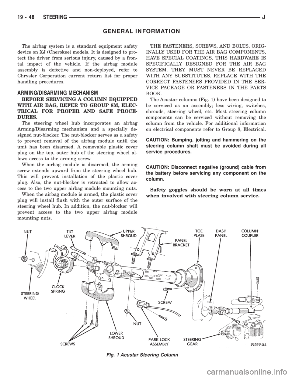
The Acustar columns (Fig. 1) have been designed to
be serviced as an assembly; less wiring, switches,
shrouds, steering wheel, etc. Most steering column
components can be serviced without removing the
column from the vehicle. For additional information
on electrical components refer to Group 8, Electrical.
CAUTION: Bumping, jolting and hammering on the
steering column shaft must be avoided during all
service procedures.
CAUTION: Disconnect negative (ground) cable from
the battery before servicing any component on the
column.
Safety goggles should be worn at all times
when involved with steering column service.
Fig. 1 Acustar Steering Column
19 - 48 STEERINGJ
Page 1535 of 2158
CLOCKSPRING
WARNING: BEFORE SERVICING AIR BAG SYSTEM,
REMOVE AND ISOLATE BATTERY NEGATIVE (-) CA-
BLE (GROUND) FROM VEHICLE BATTERY. WHEN
AN UNDEPLOYED AIR BAG ASSEMBLY IS TO BE
REMOVED FROM THE STEERING WHEEL, DISCON-
NECT THE BATTERY GROUND CABLE AND ISO-
LATE.
REMOVAL
(1) Place the front wheels in the straight ahead po-
sition before starting the repair.
(2) Disconnect battery negative cable and isolate.
(3) Remove the steering wheel and air bag, refer to
Steering Wheel Removal.
(4) Remove upper and lower steering column
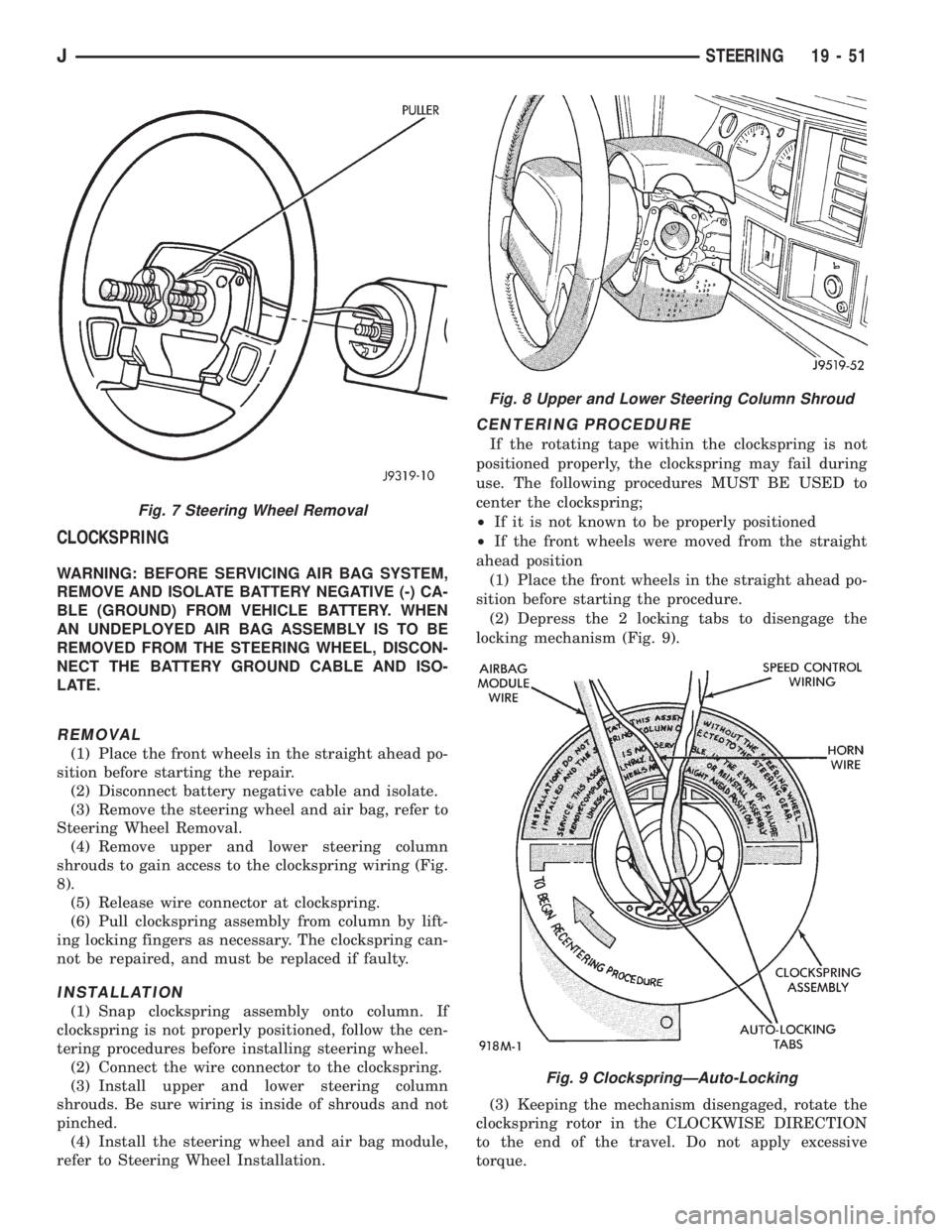
shrouds to gain access to the clockspring wiring (Fig.
8).
(5) Release wire connector at clockspring.
(6) Pull clockspring assembly from column by lift-
ing locking fingers as necessary. The clockspring can-
not be repaired, and must be replaced if faulty.
INSTALLATION
(1) Snap clockspring assembly onto column. If
clockspring is not properly positioned, follow the cen-
tering procedures before installing steering wheel.
(2) Connect the wire connector to the clockspring.
(3) Install upper and lower steering column
shrouds. Be sure wiring is inside of shrouds and not
pinched.
(4) Install the steering wheel and air bag module,
refer to Steering Wheel Installation.
CENTERING PROCEDURE
If the rotating tape within the clockspring is not
positioned properly, the clockspring may fail during
use. The following procedures MUST BE USED to
center the clockspring;
²If it is not known to be properly positioned
²If the front wheels were moved from the straight
ahead position
(1) Place the front wheels in the straight ahead po-
sition before starting the procedure.
(2) Depress the 2 locking tabs to disengage the
locking mechanism (Fig. 9).
(3) Keeping the mechanism disengaged, rotate the
clockspring rotor in the CLOCKWISE DIRECTION
to the end of the travel. Do not apply excessive
torque.
Fig. 7 Steering Wheel Removal
Fig. 8 Upper and Lower Steering Column Shroud
Fig. 9 ClockspringÐAuto-Locking
JSTEERING 19 - 51