1995 JEEP YJ wiring
[x] Cancel search: wiringPage 819 of 2158

WIRING DIAGRAMS
CONTENTS
page page
8W-01 GENERAL INFORMATIONÐWIRING
DIAGRAMS...................... 8W-01-1
8W-10 FUSE/FUSE BLOCK........... 8W-10-1
8W-11 POWER DISTRIBUTION........ 8W-11-1
8W-15 GROUND DISTRIBUTION....... 8W-15-1
8W-20 CHARGING SYSTEM.......... 8W-20-1
8W-21 STARTING SYSTEM........... 8W-21-1
8W-30 FUEL/IGNITION.............. 8W-30-1
8W-31 TRANSMISSION CONTROLS.... 8W-31-1
8W-32 ANTI-LOCK BRAKES........... 8W-32-1
8W-33 VEHICLE SPEED CONTROL..... 8W-33-1
8W-40 INSTRUMENT CLUSTER....... 8W-40-1
8W-41 HORN/CIGAR LIGHTER........ 8W-41-1
8W-42 AIR CONDITIONING/HEATER.... 8W-42-1
8W-44 INTERIOR LIGHTING.......... 8W-44-1
8W-47 AUDIO SYSTEM.............. 8W-47-18W-48 HEATED REAR WINDOW....... 8W-48-1
8W-49 OVERHEAD CONSOLE.......... 8W-49-1
8W-50 FRONT LIGHTING............ 8W-50-1
8W-51 REAR LIGHTING............. 8W-51-1
8W-52 TURN SIGNALS.............. 8W-52-1
8W-53 WIPERS.................... 8W-53-1
8W-54 TRAILER TOW................ 8W-54-1
8W-60 POWER WINDOWS............ 8W-60-1
8W-61 POWER DOOR LOCKS......... 8W-61-1
8W-62 POWER MIRRORS............ 8W-62-1
8W-63 POWER SEAT................ 8W-63-1
8W-70 SPLICE INFORMATION........ 8W-70-1
8W-80 CONNECTOR PIN OUTS....... 8W-80-1
8W-90 CONNECTOR LOCATIONS...... 8W-90-1
8W-95 SPLICE LOCATIONS........... 8W-95-1
HOW TO USE THIS GROUP
The purpose of this group is to show the electrical
circuits in a clear, simple fashion and to make trou-
bleshooting easier. Components that work together
are shown together. All electrical components used in
a specific system are shown on one diagram. The feed
for a system is shown at the top of the page. All
wires, connectors, splices, and components are shown
in the flow of current to the bottom of the page. Wir-
ing which is not part of the circuit represented is ref-
erenced to another page/section, where the complete
circuit is shown. In addition, all switches, compo-
nents, and modules are shown in theat rest posi-
tion with the doors closed and the key removed
from the ignition.
If a component is part of several different circuits,
it is shown in the diagram for each. For example, the
headlamp switch is the main part of the exterior
lighting, but it also affects the interior lighting and
the chime warning system.
It is important to realize that no attempt is
made on the diagrams to represent components
and wiring as they appear on the vehicle. For
example, a short piece of wire is treated the
same as a long one. In addition, switches and
other components are shown as simply as pos-
sible, with regard to function only.
The wiring diagram show circuits for all wheel-
bases. If there is a difference in systems or compo-
nents between wheel-bases, an identifier is placed
next to the component.
SECTION IDENTIFICATION
Sections in Group 8W are organized by sub-sys-
tems. The sections contain circuit operation descrip-
tions, helpful information, and system diagrams. The
intention is to organize information by system, con-
sistently from year to year.
CONNECTOR LOCATIONS
Section 8W-90 contains Connector Location illus-
trations. The illustrations contain the connector
number and component identification. Connector Lo-
cation charts in Section 8W-90 reference the illustra-
tion number for components and connectors.
Section 8W-80 shows each connector and the cir-
cuits involved with that connector. The connectors
are identified using the number on the Diagram
pages.
SPLICE LOCATIONS
Splice Location charts in Section 8W-70 show the
entire splice, and provide references to other sections
the splice serves.
Section 8W-95 contains illustrations that show the
general location of the splices in each harness. The
illustrations show the splice by number, and provide
a written location.
JWIRING DIAGRAMSÐXJ-RHD 8W - 1 - 1
Page 821 of 2158
FUSE/FUSE BLOCK
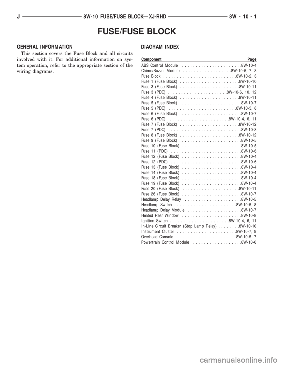
GENERAL INFORMATION
This section covers the Fuse Block and all circuits
involved with it. For additional information on sys-
tem operation, refer to the appropriate section of the
wiring diagrams.
DIAGRAM INDEX
Component Page
ABS Control Module......................8W-10-4
Chime/Buzzer Module..................8W-10-5, 7, 8
Fuse Block...........................8W-10-2, 3
Fuse 1 (Fuse Block)......................8W-10-10
Fuse 3 (Fuse Block)......................8W-10-11
Fuse 3 (PDC)......................8W-10-6, 10, 12
Fuse 4 (Fuse Block)......................8W-10-11
Fuse 5 (Fuse Block).......................8W-10-7
Fuse 5 (PDC).........................8W-10-5, 8
Fuse 6 (Fuse Block).......................8W-10-7
Fuse 6 (PDC)......................8W-10-4, 6, 11
Fuse 7 (Fuse Block)......................8W-10-12
Fuse 7 (PDC)...........................8W-10-8
Fuse 8 (Fuse Block)......................8W-10-12
Fuse 9 (Fuse Block).......................8W-10-5
Fuse 10 (Fuse Block)......................8W-10-5
Fuse 11 (PDC)..........................8W-10-6
Fuse 12 (Fuse Block)......................8W-10-4
Fuse 12 (PDC)..........................8W-10-6
Fuse 13 (Fuse Block)......................8W-10-4
Fuse 14 (Fuse Block)......................8W-10-4
Fuse 18 (Fuse Block)......................8W-10-4
Fuse 19 (Fuse Block)......................8W-10-4
Fuse 20 (Fuse Block).....................8W-10-11
Fuse 26 (Fuse Block)......................8W-10-7
Headlamp Delay Relay.....................8W-10-5
Headlamp Switch.......................8W-10-5, 8
Headlamp Delay Module....................8W-10-7
Heated Rear Window......................8W-10-8
Ignition Switch......................8W-10-4, 6, 11
In-Line Circuit Breaker (Stop Lamp Relay)........8W-10-10
Instrument Cluster......................8W-10-7, 9
Overhead Console......................8W-10-5, 7
Powertrain Control Module..................8W-10-6
J8W-10 FUSE/FUSE BLOCKÐXJ-RHD 8W - 10 - 1
Page 833 of 2158
POWER DISTRIBUTION
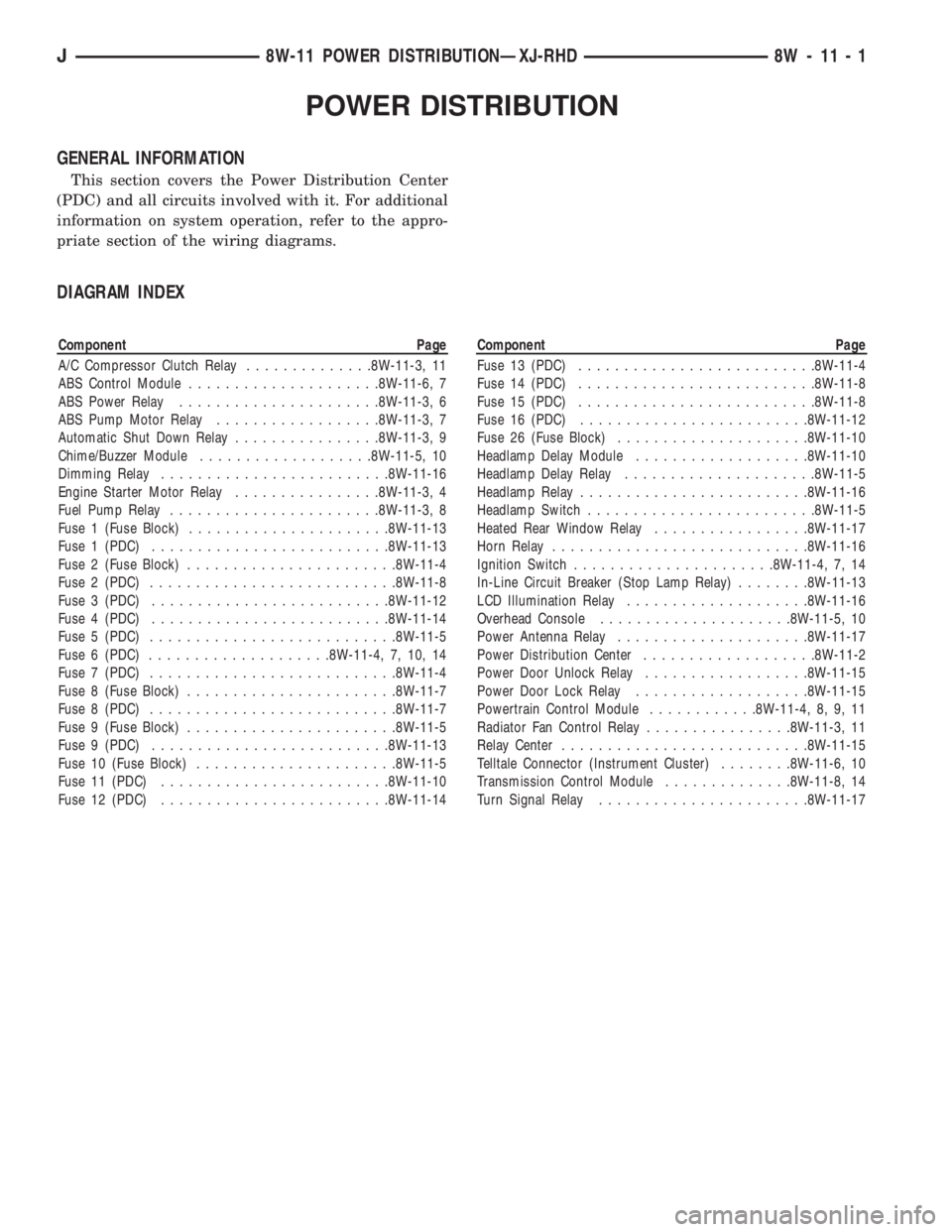
GENERAL INFORMATION
This section covers the Power Distribution Center
(PDC) and all circuits involved with it. For additional
information on system operation, refer to the appro-
priate section of the wiring diagrams.
DIAGRAM INDEX
Component Page
A/C Compressor Clutch Relay..............8W-11-3, 11
ABS Control Module.....................8W-11-6, 7
ABS Power Relay......................8W-11-3, 6
ABS Pump Motor Relay..................8W-11-3, 7
Automatic Shut Down Relay................8W-11-3, 9
Chime/Buzzer Module...................8W-11-5, 10
Dimming Relay.........................8W-11-16
Engine Starter Motor Relay................8W-11-3, 4
Fuel Pump Relay.......................8W-11-3, 8
Fuse 1 (Fuse Block)......................8W-11-13
Fuse 1 (PDC)..........................8W-11-13
Fuse 2 (Fuse Block).......................8W-11-4
Fuse 2 (PDC)...........................8W-11-8
Fuse 3 (PDC)..........................8W-11-12
Fuse 4 (PDC)..........................8W-11-14
Fuse 5 (PDC)...........................8W-11-5
Fuse 6 (PDC)....................8W-11-4, 7, 10, 14
Fuse 7 (PDC)...........................8W-11-4
Fuse 8 (Fuse Block).......................8W-11-7
Fuse 8 (PDC)...........................8W-11-7
Fuse 9 (Fuse Block).......................8W-11-5
Fuse 9 (PDC)..........................8W-11-13
Fuse 10 (Fuse Block)......................8W-11-5
Fuse 11 (PDC).........................8W-11-10
Fuse 12 (PDC).........................8W-11-14Component Page
Fuse 13 (PDC)..........................8W-11-4
Fuse 14 (PDC)..........................8W-11-8
Fuse 15 (PDC)..........................8W-11-8
Fuse 16 (PDC).........................8W-11-12
Fuse 26 (Fuse Block).....................8W-11-10
Headlamp Delay Module...................8W-11-10
Headlamp Delay Relay.....................8W-11-5
Headlamp Relay.........................8W-11-16
Headlamp Switch.........................8W-11-5
Heated Rear Window Relay.................8W-11-17
Horn Relay............................8W-11-16
Ignition Switch......................8W-11-4, 7, 14
In-Line Circuit Breaker (Stop Lamp Relay)........8W-11-13
LCD Illumination Relay....................8W-11-16
Overhead Console.....................8W-11-5, 10
Power Antenna Relay.....................8W-11-17
Power Distribution Center...................8W-11-2
Power Door Unlock Relay..................8W-11-15
Power Door Lock Relay...................8W-11-15
Powertrain Control Module............8W-11-4, 8, 9, 11
Radiator Fan Control Relay................8W-11-3, 11
Relay Center...........................8W-11-15
Telltale Connector (Instrument Cluster)........8W-11-6, 10
Transmission Control Module..............8W-11-8, 14
Turn Signal Relay.......................8W-11-17
J8W-11 POWER DISTRIBUTIONÐXJ-RHD 8W - 11 - 1
Page 851 of 2158
GROUND DISTRIBUTION
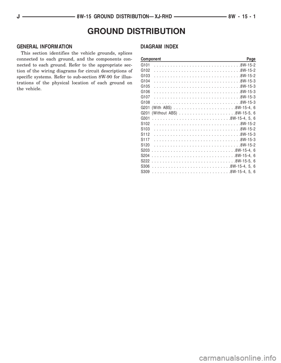
GENERAL INFORMATION
This section identifies the vehicle grounds, splices
connected to each ground, and the components con-
nected to each ground. Refer to the appropriate sec-
tion of the wiring diagrams for circuit descriptions of
specific systems. Refer to sub-section 8W-90 for illus-
trations of the physical location of each ground on
the vehicle.
DIAGRAM INDEX
Component Page
G101................................8W-15-2
G102................................8W-15-2
G103................................8W-15-2
G104................................8W-15-3
G105................................8W-15-3
G106................................8W-15-3
G107................................8W-15-3
G108................................8W-15-3
G201 (With ABS).......................8W-15-4, 6
G201 (Without ABS).....................8W-15-5, 6
G301.............................8W-15-4, 5, 6
S102................................8W-15-2
S103................................8W-15-2
S112................................8W-15-3
S117................................8W-15-3
S120................................8W-15-2
S203...............................8W-15-4, 6
S204...............................8W-15-4, 6
S222...............................8W-15-5, 6
S306.............................8W-15-4, 5, 6
S309.............................8W-15-4, 5, 6
J8W-15 GROUND DISTRIBUTIONÐXJ-RHD 8W - 15 - 1
Page 907 of 2158
AIR CONDITIONING/HEATER
CONTENTS
page page
A/C-HEATER SYSTEM...................... 1 HEATERSYSTEM......................... 1
GENERAL INFORMATION
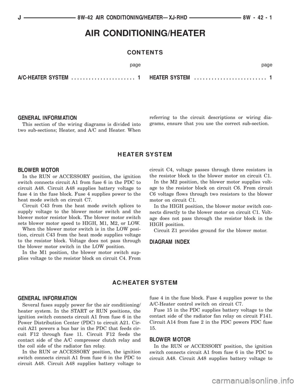
This section of the wiring diagrams is divided into
two sub-sections; Heater, and A/C and Heater. Whenreferring to the circuit descriptions or wiring dia-
grams, ensure that you use the correct sub-section.
HEATER SYSTEM
BLOWER MOTOR
In the RUN or ACCESSORY position, the ignition
switch connects circuit A1 from fuse 6 in the PDC to
circuit A48. Circuit A48 supplies battery voltage to
fuse 4 in the fuse block. Fuse 4 supplies power to the
heat mode switch on circuit C7.
Circuit C43 from the heat mode switch splices to
supply voltage to the blower motor switch and the
blower motor resistor block. The blower motor switch
sets blower motor speed to HIGH, M1, M2, or LOW.
When the blower motor switch is in the LOW posi-
tion, circuit C43 from the heat mode supplies voltage
to the resistor block. Voltage does not pass through
the blower motor switch in the LOW position.
In the M1 position, the blower motor switch sup-
plies voltage to the resistor block on circuit C4. Fromcircuit C4, voltage passes through three resistors in
the resistor block to the blower motor on circuit C1.
In the M2 position, the blower motor supplies volt-
age to the resistor block on circuit C6. From circuit
C6 voltage flows through two resistors to the blower
motor on circuit C1.
In the HIGH position, the blower motor switch con-
nects directly to the blower motor on circuit C1. Volt-
age does not pass through the resistor block in the
HIGH position.
Circuit Z1 provides ground for the blower motor.
DIAGRAM INDEX
AC/HEATER SYSTEM
GENERAL INFORMATION
Several fuses supply power for the air conditioning/
heater system. In the START or RUN positions, the
ignition switch connects circuit A1 from fuse 6 in the
Power Distribution Center (PDC) to circuit A21. Cir-
cuit A21 powers a bus bar in the PDC that feeds cir-
cuit F12 through fuse 11. Circuit F12 feeds the
contact side of the A/C compressor clutch relay and
the coil side of the radiator fan relay.
In the RUN or ACCESSORY position, the ignition
switch connects circuit A1 from fuse 6 in the PDC to
circuit A48. Circuit A48 supplies battery voltage tofuse 4 in the fuse block. Fuse 4 supplies power to the
A/C-Heater control switch on circuit C7.
Fuse 15 in the PDC supplies battery voltage to the
contact side of the radiator fan relay on circuit F141.
Circuit A14 from fuse 2 in the PDC powers PDC fuse
15.
BLOWER MOTOR
In the RUN or ACCESSORY position, the ignition
switch connects circuit A1 from fuse 6 in the PDC to
circuit A48. Circuit A48 supplies battery voltage to
J8W-42 AIR CONDITIONING/HEATERÐXJ-RHD 8W - 42 - 1
Page 965 of 2158
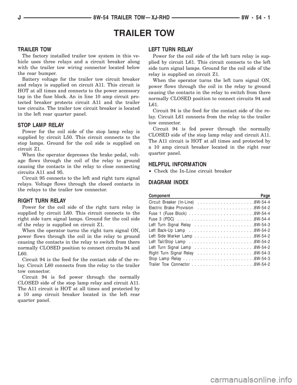
TRAILER TOW
TRAILER TOW
The factory installed trailer tow system in this ve-
hicle uses three relays and a circuit breaker along
with the trailer tow wiring connector located below
the rear bumper.
Battery voltage for the trailer tow circuit breaker
and relays is supplied on circuit A11. This circuit is
HOT at all times and connects to the power accessory
tap in the fuse block. An in line 10 amp circuit pro-
tected breaker protects circuit A11 and the trailer
tow circuits. The trailer tow circuit breaker is located
in the left rear quarter panel.
STOP LAMP RELAY
Power for the coil side of the stop lamp relay is
supplied by circuit L50. This circuit connects to the
stop lamps. Ground for the coil side is supplied on
circuit Z1.
When the operator depresses the brake pedal, volt-
age flows through the coil of the relay to ground
causing the contacts in the relay to close connecting
circuits A11 and 95.
Circuit 95 connects to the left and right turn signal
relays. Voltage flows through the closed contacts in
the relays to the trailer tow connector.
RIGHT TURN RELAY
Power for the coil side of the right turn relay is
supplied by circuit L60. This circuit connects to the
right side turn signal lamps. Ground for the coil side
of the relay is supplied on circuit Z1.
When the operator turns the right turn signal ON,
power flows through the coil in the relay to ground
causing the contacts in the relay to switch from there
normally CLOSED position to connect circuits 94 and
L60.
Circuit 94 is the feed for the contact side of the re-
lay. Circuit L60 connects from the relay to the trailer
tow connector.
Circuit 94 is fed power through the normally
CLOSED side of the stop lamp relay and circuit A11.
The A11 circuit is HOT at all times and protected by
a 10 amp circuit breaker located in the left rear
quarter panel.
LEFT TURN RELAY
Power for the coil side of the left turn relay is sup-
plied by circuit L61. This circuit connects to the left
side turn signal lamps. Ground for the coil side of the
relay is supplied on circuit Z1.
When the operator turns the left turn signal ON,
power flows through the coil in the relay to ground
causing the contacts in the relay to switch from there
normally CLOSED position to connect circuits 94 and
L61.
Circuit 94 is the feed for the contact side of the re-
lay. Circuit L61 connects from the relay to the trailer
tow connector.
Circuit 94 is fed power through the normally
CLOSED side of the stop lamp relay and circuit A11.
The A11 circuit is HOT at all times and protected by
a 10 amp circuit breaker located in the right rear
quarter panel.
HELPFUL INFORMATION
²Check the In-Line circuit breaker
DIAGRAM INDEX
Component Page
Circuit Breaker (In-Line)....................8W-54-4
Electric Brake Provision....................8W-54-2
Fuse 1 (Fuse Block).......................8W-54-4
Fuse 3 (PDC)...........................8W-54-4
Left Turn Signal Relay.....................8W-54-3
Left Back-Up Lamp.......................8W-54-2
Left Side Marker Lamp.....................8W-54-2
Left Tail/Stop Lamp.......................8W-54-2
Left Turn Signal Lamp.....................8W-54-2
Right Turn Signal Relay....................8W-54-3
Stop Lamp Relay.........................8W-54-3
Trailer Tow Connector......................8W-54-2
J8W-54 TRAILER TOWÐXJ-RHD 8W - 54 - 1
Page 982 of 2158
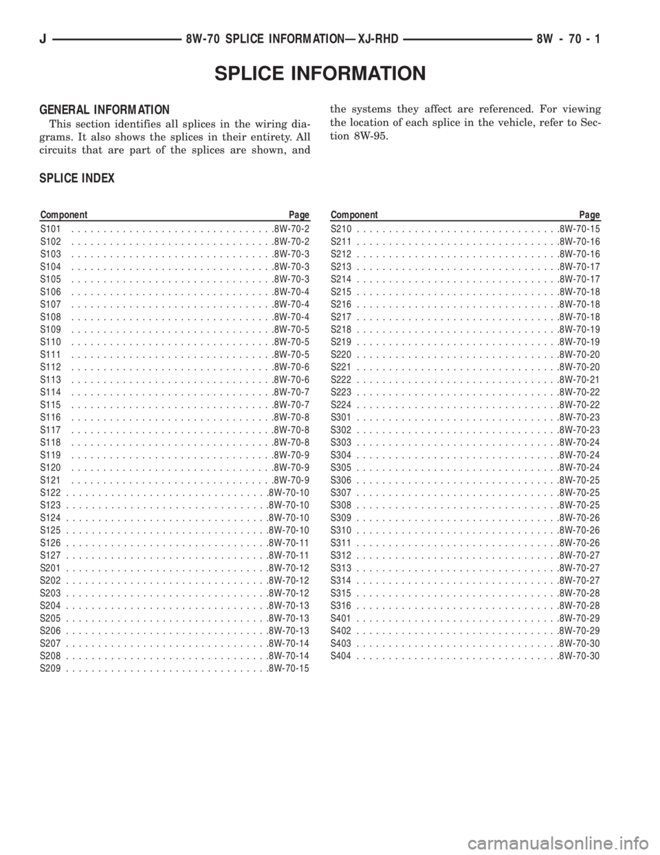
SPLICE INFORMATION
GENERAL INFORMATION
This section identifies all splices in the wiring dia-
grams. It also shows the splices in their entirety. All
circuits that are part of the splices are shown, andthe systems they affect are referenced. For viewing
the location of each splice in the vehicle, refer to Sec-
tion 8W-95.
SPLICE INDEX
Component Page
S101................................8W-70-2
S102................................8W-70-2
S103................................8W-70-3
S104................................8W-70-3
S105................................8W-70-3
S106................................8W-70-4
S107................................8W-70-4
S108................................8W-70-4
S109................................8W-70-5
S110................................8W-70-5
S111................................8W-70-5
S112................................8W-70-6
S113................................8W-70-6
S114................................8W-70-7
S115................................8W-70-7
S116................................8W-70-8
S117................................8W-70-8
S118................................8W-70-8
S119................................8W-70-9
S120................................8W-70-9
S121................................8W-70-9
S122................................8W-70-10
S123................................8W-70-10
S124................................8W-70-10
S125................................8W-70-10
S126................................8W-70-11
S127................................8W-70-11
S201................................8W-70-12
S202................................8W-70-12
S203................................8W-70-12
S204................................8W-70-13
S205................................8W-70-13
S206................................8W-70-13
S207................................8W-70-14
S208................................8W-70-14
S209................................8W-70-15Component Page
S210................................8W-70-15
S211................................8W-70-16
S212................................8W-70-16
S213................................8W-70-17
S214................................8W-70-17
S215................................8W-70-18
S216................................8W-70-18
S217................................8W-70-18
S218................................8W-70-19
S219................................8W-70-19
S220................................8W-70-20
S221................................8W-70-20
S222................................8W-70-21
S223................................8W-70-22
S224................................8W-70-22
S301................................8W-70-23
S302................................8W-70-23
S303................................8W-70-24
S304................................8W-70-24
S305................................8W-70-24
S306................................8W-70-25
S307................................8W-70-25
S308................................8W-70-25
S309................................8W-70-26
S310................................8W-70-26
S311................................8W-70-26
S312................................8W-70-27
S313................................8W-70-27
S314................................8W-70-27
S315................................8W-70-28
S316................................8W-70-28
S401................................8W-70-29
S402................................8W-70-29
S403................................8W-70-30
S404................................8W-70-30
J8W-70 SPLICE INFORMATIONÐXJ-RHD 8W - 70 - 1
Page 1067 of 2158
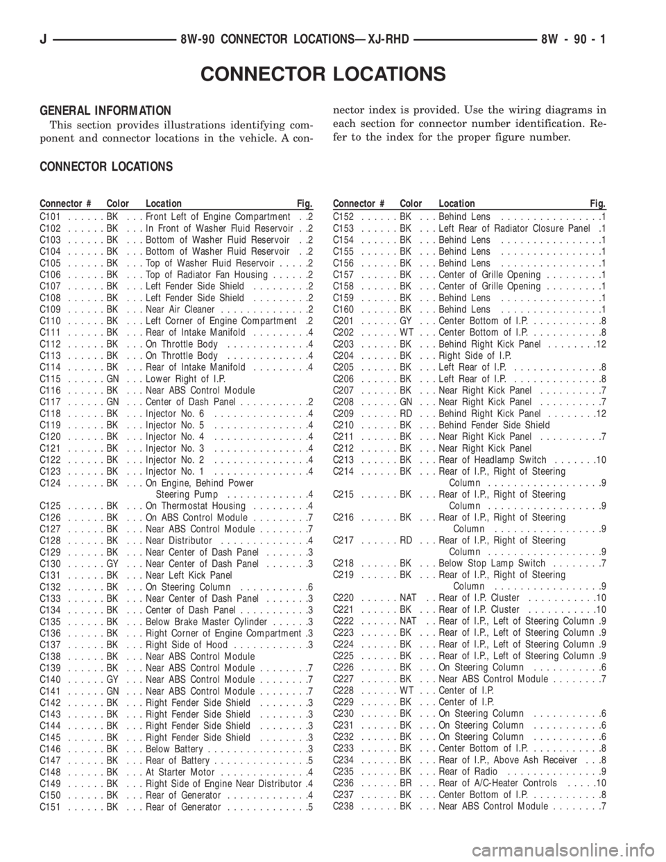
CONNECTOR LOCATIONS
GENERAL INFORMATION
This section provides illustrations identifying com-
ponent and connector locations in the vehicle. A con-nector index is provided. Use the wiring diagrams in
each section for connector number identification. Re-
fer to the index for the proper figure number.
CONNECTOR LOCATIONS
Connector # Color Location Fig.
C101......BK ...Front Left of Engine Compartment . .2
C102......BK ...InFront of Washer Fluid Reservoir . .2
C103......BK ...Bottom of Washer Fluid Reservoir . .2
C104......BK ...Bottom of Washer Fluid Reservoir . .2
C105......BK ...TopofWasher Fluid Reservoir.....2
C106......BK ...TopofRadiator Fan Housing......2
C107......BK ...Left Fender Side Shield.........2
C108......BK ...Left Fender Side Shield.........2
C109......BK ...Near Air Cleaner..............2
C110......BK ...Left Corner of Engine Compartment .2
C111......BK ...Rear of Intake Manifold.........4
C112......BK ...OnThrottle Body.............4
C113......BK ...OnThrottle Body.............4
C114......BK ...Rear of Intake Manifold.........4
C115......GN ...Lower Right of I.P.
C116......BK ...Near ABS Control Module
C117......GN ...Center of Dash Panel...........2
C118......BK ...Injector No. 6...............4
C119......BK ...Injector No. 5...............4
C120......BK ...Injector No. 4...............4
C121......BK ...Injector No. 3...............4
C122......BK ...Injector No. 2...............4
C123......BK ...Injector No. 1...............4
C124......BK ...OnEngine, Behind Power
Steering Pump.............4
C125......BK ...OnThermostat Housing.........4
C126......BK ...OnABSControl Module.........7
C127......BK ...Near ABS Control Module........7
C128......BK ...Near Distributor..............4
C129......BK ...Near Center of Dash Panel.......3
C130......GY ...Near Center of Dash Panel.......3
C131......BK ...Near Left Kick Panel
C132......BK ...OnSteering Column...........6
C133......BK ...Near Center of Dash Panel.......3
C134......BK ...Center of Dash Panel...........3
C135......BK ...Below Brake Master Cylinder......3
C136......BK ...Right Corner of Engine Compartment .3
C137......BK ...Right Side of Hood............3
C138......BK ...Near ABS Control Module
C139......BK ...Near ABS Control Module........7
C140......GY ...Near ABS Control Module........7
C141......GN ...Near ABS Control Module........7
C142......BK ...Right Fender Side Shield........3
C143......BK ...Right Fender Side Shield........3
C144......BK ...Right Fender Side Shield........3
C145......BK ...Right Fender Side Shield........3
C146......BK ...Below Battery................3
C147......BK ...Rear of Battery...............5
C148......BK ...AtStarter Motor..............4
C149......BK ...Right Side of Engine Near Distributor .4
C150......BK ...Rear of Generator.............4
C151......BK ...Rear of Generator.............5Connector # Color Location Fig.
C152......BK ...Behind Lens................1
C153......BK ...Left Rear of Radiator Closure Panel .1
C154......BK ...Behind Lens................1
C155......BK ...Behind Lens................1
C156......BK ...Behind Lens................1
C157......BK ...Center of Grille Opening.........1
C158......BK ...Center of Grille Opening.........1
C159......BK ...Behind Lens................1
C160......BK ...Behind Lens................1
C201......GY ...Center Bottom of I.P............8
C202......WT ...Center Bottom of I.P............8
C203......BK ...Behind Right Kick Panel........12
C204......BK ...Right Side of I.P.
C205......BK ...Left Rear of I.P...............8
C206......BK ...Left Rear of I.P...............8
C207......BK ...Near Right Kick Panel..........7
C208......GN ...Near Right Kick Panel..........7
C209......RD ...Behind Right Kick Panel........12
C210......BK ...Behind Fender Side Shield
C211......BK ...Near Right Kick Panel..........7
C212......BK ...Near Right Kick Panel
C213......BK ...Rear of Headlamp Switch.......10
C214......BK ...Rear of I.P., Right of Steering
Column..................9
C215......BK ...Rear of I.P., Right of Steering
Column..................9
C216......BK ...Rear of I.P., Right of Steering
Column.................9
C217......RD ...Rear of I.P., Right of Steering
Column..................9
C218......BK ...Below Stop Lamp Switch........7
C219......BK ...Rear of I.P., Right of Steering
Column.................9
C220......NAT ..Rear of I.P. Cluster...........10
C221......BK ...Rear of I.P. Cluster...........10
C222......NAT ..Rear of I.P., Left of Steering Column .9
C223......BK ...Rear of I.P., Left of Steering Column .9
C224......BK ...Rear of I.P., Left of Steering Column .9
C225......BK ...Rear of I.P., Left of Steering Column .9
C226......BK ...OnSteering Column...........6
C227......BK ...Near ABS Control Module........7
C228......WT ...Center of I.P.
C229......BK ...Center of I.P.
C230......BK ...OnSteering Column...........6
C231......BK ...OnSteering Column...........6
C232......BK ...OnSteering Column...........6
C233......BK ...Center Bottom of I.P............8
C234......BK ...Rear of I.P., Above Ash Receiver . . .8
C235......BK ...Rear of Radio...............9
C236......BR ...Rear of A/C-Heater Controls.....10
C237......BK ...Center Bottom of I.P............8
C238......BK ...Near ABS Control Module........7
J8W-90 CONNECTOR LOCATIONSÐXJ-RHD 8W - 90 - 1