1995 JEEP YJ wiring
[x] Cancel search: wiringPage 1168 of 2158
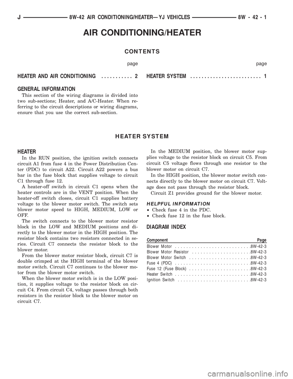
AIR CONDITIONING/HEATER
CONTENTS
page page
HEATER AND AIR CONDITIONING........... 2 HEATERSYSTEM......................... 1
GENERAL INFORMATION
This section of the wiring diagrams is divided into
two sub-sections; Heater, and A/C-Heater. When re-
ferring to the circuit descriptions or wiring diagrams,
ensure that you use the correct sub-section.
HEATER SYSTEM
HEATER
In the RUN position, the ignition switch connects
circuit A1 from fuse 4 in the Power Distribution Cen-
ter (PDC) to circuit A22. Circuit A22 powers a bus
bar in the fuse block that supplies voltage to circuit
C1 through fuse 12.
A heater-off switch in circuit C1 opens when the
heater controls are in the VENT position. When the
heater-off switch closes, circuit C1 supplies battery
voltage to the blower motor switch. The switch sets
blower motor speed to HIGH, MEDIUM, LOW or
OFF.
The switch connects to the blower motor resistor
block in the LOW and MEDIUM positions and di-
rectly to the blower motor in the HIGH position. The
resistor block contains two resistors connected in se-
ries. Circuit C7 connects the resistor block to the
blower motor.
From the blower motor resistor block, circuit C7 is
double crimped at the HIGH terminal of the blower
motor switch. Circuit C7 continues to the blower mo-
tor from the blower motor switch.
When the blower motor switch is in the LOW posi-
tion, it supplies voltage to the resistor block on cir-
cuit C4. From circuit C4, voltage passes through both
resistors in the resistor block to the blower motor on
circuit C7.In the MEDIUM position, the blower motor sup-
plies voltage to the resistor block on circuit C5. From
circuit C5 voltage flows through one resistor to the
blower motor on circuit C7.
In the HIGH position, the blower motor switch con-
nects directly to the blower motor on circuit C7. Volt-
age does not pass through the resistor block.
Circuit Z1 provides ground for the blower motor.
HELPFUL INFORMATION
²Check fuse 4 in the PDC.
²Check fuse 12 in the fuse block.
DIAGRAM INDEX
Component Page
Blower Motor...........................8W-42-3
Blower Motor Resistor.....................8W-42-3
Blower Motor Switch......................8W-42-3
Fuse 4 (PDC)...........................8W-42-3
Fuse 12 (Fuse Block)......................8W-42-3
Heater Switch...........................8W-42-3
Ignition Switch..........................8W-42-3
J8W-42 AIR CONDITIONING/HEATERÐYJ VEHICLES 8W - 42 - 1
Page 1216 of 2158
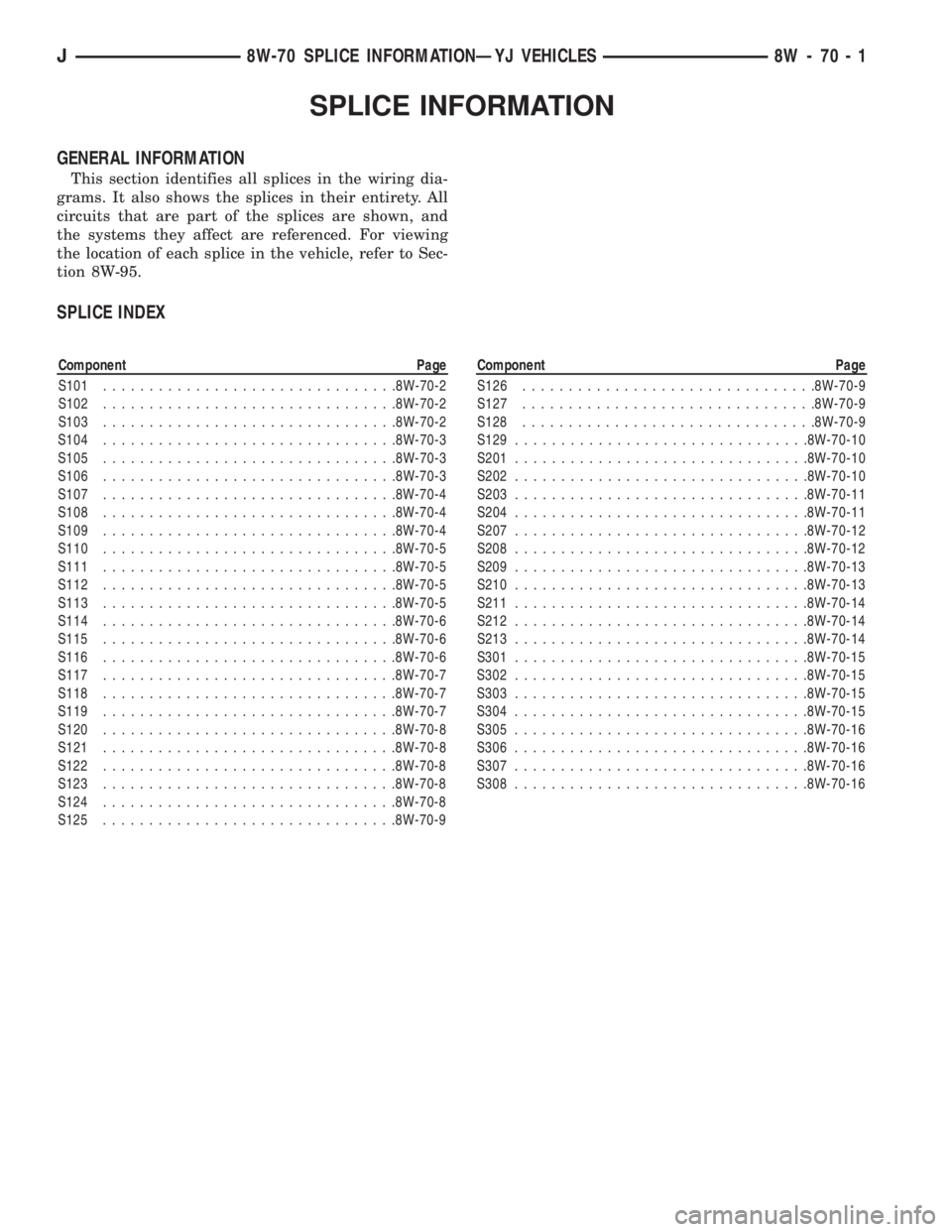
SPLICE INFORMATION
GENERAL INFORMATION
This section identifies all splices in the wiring dia-
grams. It also shows the splices in their entirety. All
circuits that are part of the splices are shown, and
the systems they affect are referenced. For viewing
the location of each splice in the vehicle, refer to Sec-
tion 8W-95.
SPLICE INDEX
Component Page
S101................................8W-70-2
S102................................8W-70-2
S103................................8W-70-2
S104................................8W-70-3
S105................................8W-70-3
S106................................8W-70-3
S107................................8W-70-4
S108................................8W-70-4
S109................................8W-70-4
S110................................8W-70-5
S111................................8W-70-5
S112................................8W-70-5
S113................................8W-70-5
S114................................8W-70-6
S115................................8W-70-6
S116................................8W-70-6
S117................................8W-70-7
S118................................8W-70-7
S119................................8W-70-7
S120................................8W-70-8
S121................................8W-70-8
S122................................8W-70-8
S123................................8W-70-8
S124................................8W-70-8
S125................................8W-70-9Component Page
S126................................8W-70-9
S127................................8W-70-9
S128................................8W-70-9
S129................................8W-70-10
S201................................8W-70-10
S202................................8W-70-10
S203................................8W-70-11
S204................................8W-70-11
S207................................8W-70-12
S208................................8W-70-12
S209................................8W-70-13
S210................................8W-70-13
S211................................8W-70-14
S212................................8W-70-14
S213................................8W-70-14
S301................................8W-70-15
S302................................8W-70-15
S303................................8W-70-15
S304................................8W-70-15
S305................................8W-70-16
S306................................8W-70-16
S307................................8W-70-16
S308................................8W-70-16
J8W-70 SPLICE INFORMATIONÐYJ VEHICLES 8W - 70 - 1
Page 1262 of 2158
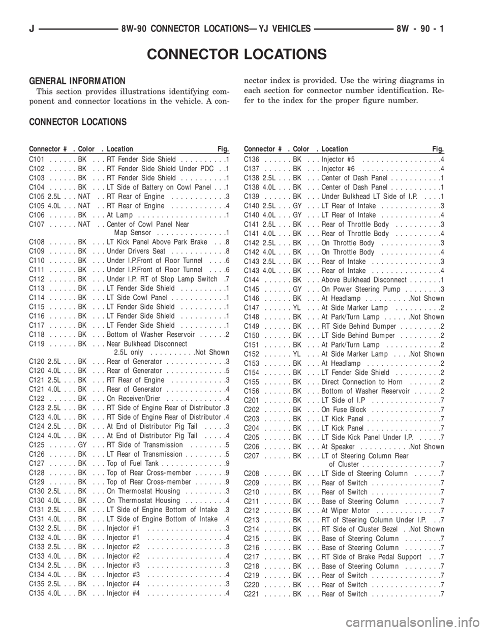
CONNECTOR LOCATIONS
GENERAL INFORMATION
This section provides illustrations identifying com-
ponent and connector locations in the vehicle. A con-nector index is provided. Use the wiring diagrams in
each section for connector number identification. Re-
fer to the index for the proper figure number.
CONNECTOR LOCATIONS
Connector # . Color . Location Fig.
C101......BK ...RTFender Side Shield..........1
C102......BK ...RTFender Side Shield Under PDC . .1
C103......BK ...RTFender Side Shield..........1
C104......BK ...LTSide of Battery on Cowl Panel . . .1
C105 2.5L . . . NAT . . RT Rear of Engine............3
C105 4.0L . . . NAT . . RT Rear of Engine............4
C106......BK ...AtLamp...................1
C107......NAT ..Center of Cowl Panel Near
Map Sensor...............1
C108......BK ...LTKick Panel Above Park Brake . . .8
C109......BK ...Under Drivers Seat............8
C110......BK ...Under I.P.Front of Floor Tunnel....6
C111......BK ...Under I.P.Front of Floor Tunnel....6
C112......BK ...Under I.P. RT of Stop Lamp Switch .7
C113......BK ...LTFender Side Shield..........1
C114......BK ...LTSide Cowl Panel............1
C115......BK ...LTFender Side Shield..........1
C116......BK ...LTFender Side Shield..........1
C117......BK ...LTFender Side Shield..........1
C118......BK ...Bottom of Washer Reservoir......2
C119......BK ...Near Bulkhead Disconnect
2.5L only..........Not Shown
C120 2.5L . . . BK . . . Rear of Generator.............3
C120 4.0L . . . BK . . . Rear of Generator.............5
C121 2.5L . . . BK . . . RT Rear of Engine............3
C121 4.0L . . . BK . . . Rear of Generator.............4
C122......BK ...OnReceiver/Drier.............4
C123 2.5L . . . BK . . . RT Side of Engine Rear of Distributor .3
C123 4.0L . . . BK . . . RT Side of Engine Rear of Distributor .4
C124 2.5L . . . BK . . . At End of Distributor Pig Tail.....3
C124 4.0L . . . BK . . . At End of Distributor Pig Tail.....4
C125......GY ...RTSide of Transmission........5
C126......BK ...LTRear of Transmission.........5
C127......BK ...TopofFuel Tank..............9
C128......BK ...TopofRear Cross-member.......9
C129......BK ...TopofRear Cross-member.......9
C130 2.5L . . . BK . . . On Thermostat Housing.........3
C130 4.0L . . . BK . . . On Thermostat Housing.........4
C131 2.5L . . . BK . . . LT Side of Engine Bottom of Intake .3
C131 4.0L . . . BK . . . LT Side of Engine Bottom of Intake .4
C132 2.5L . . . BK . . . Injector #1.................3
C132 4.0L . . . BK . . . Injector #1.................4
C133 2.5L . . . BK . . . Injector #2.................3
C133 4.0L . . . BK . . . Injector #2.................4
C134 2.5L . . . BK . . . Injector #3.................3
C134 4.0L . . . BK . . . Injector #3.................4
C135 2.5L . . . BK . . . Injector #4.................3
C135 4.0L . . . BK . . . Injector #4.................4Connector # . Color . Location Fig.
C136......BK ...Injector #5.................4
C137......BK ...Injector #6.................4
C138 2.5L . . . BK . . . Center of Dash Panel...........1
C138 4.0L . . . BK . . . Center of Dash Panel...........1
C139......BK ...Under Bulkhead LT Side of I.P.....1
C140 2.5L . . . GY . . . LT Rear of Intake.............3
C140 4.0L . . . GY . . . LT Rear of Intake.............4
C141 2.5L . . . BK . . . Rear of Throttle Body..........3
C141 4.0L . . . BK . . . Rear of Throttle Body..........4
C142 2.5L . . . BK . . . On Throttle Body.............3
C142 4.0L . . . BK . . . On Throttle Body.............4
C143 2.5L . . . BK . . . Rear of Intake...............3
C143 4.0L . . . BK . . . Rear of Intake...............4
C144......BK ...Above Bulkhead Disconnect.......1
C145......GY ...OnPower Steering Pump........3
C146......BK ...AtHeadlamp..........Not Shown
C147......YL ...AtSide Marker Lamp..........2
C148......BK ...AtPark/Turn Lamp......Not Shown
C149......BK ...RTSide Behind Bumper.........2
C150......BK ...LTSide Behind Bumper.........2
C151......BK ...AtPark/Turn Lamp............2
C152......YL ...AtSide Marker Lamp. . . .Not Shown
C153......BK ...AtHeadlamp................2
C154......BK ...LTFender Side Shield..........2
C155......BK ...Direct Connection to Horn.......2
C156......BK ...Bottom of Washer Reservoir......2
C201......BK ...LTSide of I.P...............7
C202......BK ...OnFuse Block...............7
C203......BK ...LTKick Panel................7
C204......BK ...LTKick Panel................7
C205......BK ...LTSide Kick Panel Under I.P......7
C206......BK ...AtSpeaker...........Not Shown
C207......BK ...LTofSteering Column Rear
of Cluster.................7
C208......BK ...LTSide of Steering Column......7
C209......BK ...Rear of Switch...............7
C210......BK ...Rear of Switch...............7
C211......BK ...Base of Steering Column........7
C212......BK ...AtWiper Motor..............7
C213......BK ...RTofSteering Column Under I.P. . .7
C214......BK ...RTSide of Cluster Bezel . .Not Shown
C215......BK ...Base of Steering Column........7
C216......BK ...Base of Steering Column........7
C217......BK ...RTSide of Brake Pedal Support . . .7
C218......BK ...Base of Steering Column........7
C219......BK ...Rear of Switch...............7
C220......BK ...Rear of Switch...............7
C221......BK ...Rear of Switch...............7
J8W-90 CONNECTOR LOCATIONSÐYJ VEHICLES 8W - 90 - 1
Page 1273 of 2158
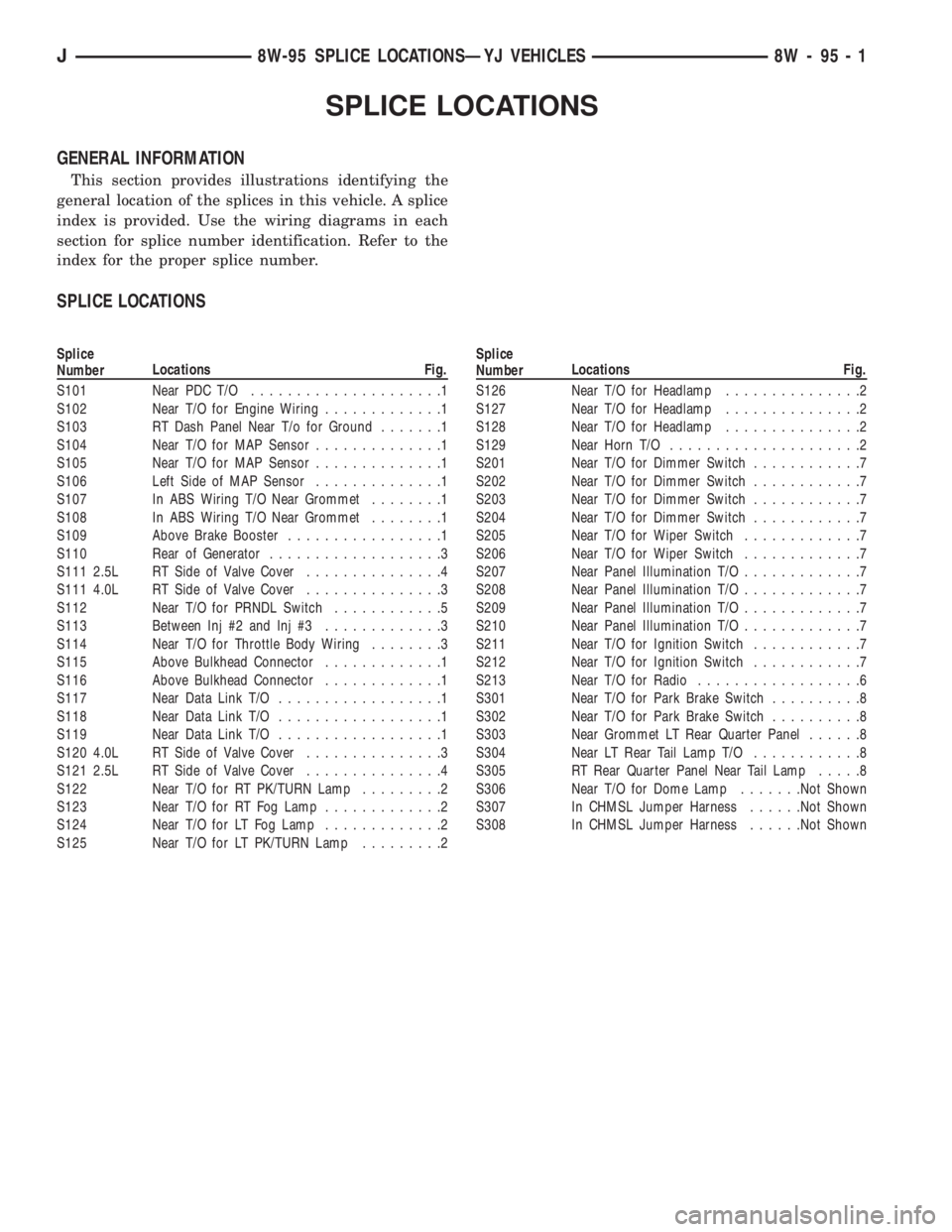
SPLICE LOCATIONS
GENERAL INFORMATION
This section provides illustrations identifying the
general location of the splices in this vehicle. A splice
index is provided. Use the wiring diagrams in each
section for splice number identification. Refer to the
index for the proper splice number.
SPLICE LOCATIONS
Splice
NumberLocations Fig.
S101 Near PDC T/O.....................1
S102 Near T/O for Engine Wiring.............1
S103 RT Dash Panel Near T/o for Ground.......1
S104 Near T/O for MAP Sensor..............1
S105 Near T/O for MAP Sensor..............1
S106 Left Side of MAP Sensor..............1
S107 In ABS Wiring T/O Near Grommet........1
S108 In ABS Wiring T/O Near Grommet........1
S109 Above Brake Booster.................1
S110 Rear of Generator...................3
S111 2.5L RT Side of Valve Cover...............4
S111 4.0L RT Side of Valve Cover...............3
S112 Near T/O for PRNDL Switch............5
S113 Between Inj #2 and Inj #3.............3
S114 Near T/O for Throttle Body Wiring........3
S115 Above Bulkhead Connector.............1
S116 Above Bulkhead Connector.............1
S117 Near Data Link T/O..................1
S118 Near Data Link T/O..................1
S119 Near Data Link T/O..................1
S120 4.0L RT Side of Valve Cover...............3
S121 2.5L RT Side of Valve Cover...............4
S122 Near T/O for RT PK/TURN Lamp.........2
S123 Near T/O for RT Fog Lamp.............2
S124 Near T/O for LT Fog Lamp.............2
S125 Near T/O for LT PK/TURN Lamp.........2Splice
NumberLocations Fig.
S126 Near T/O for Headlamp...............2
S127 Near T/O for Headlamp...............2
S128 Near T/O for Headlamp...............2
S129 Near Horn T/O.....................2
S201 Near T/O for Dimmer Switch............7
S202 Near T/O for Dimmer Switch............7
S203 Near T/O for Dimmer Switch............7
S204 Near T/O for Dimmer Switch............7
S205 Near T/O for Wiper Switch.............7
S206 Near T/O for Wiper Switch.............7
S207 Near Panel Illumination T/O.............7
S208 Near Panel Illumination T/O.............7
S209 Near Panel Illumination T/O.............7
S210 Near Panel Illumination T/O.............7
S211 Near T/O for Ignition Switch............7
S212 Near T/O for Ignition Switch............7
S213 Near T/O for Radio..................6
S301 Near T/O for Park Brake Switch..........8
S302 Near T/O for Park Brake Switch..........8
S303 Near Grommet LT Rear Quarter Panel......8
S304 Near LT Rear Tail Lamp T/O............8
S305 RT Rear Quarter Panel Near Tail Lamp.....8
S306 Near T/O for Dome Lamp.......Not Shown
S307 In CHMSL Jumper Harness......Not Shown
S308 In CHMSL Jumper Harness......Not Shown
J8W-95 SPLICE LOCATIONSÐYJ VEHICLES 8W - 95 - 1
Page 1425 of 2158
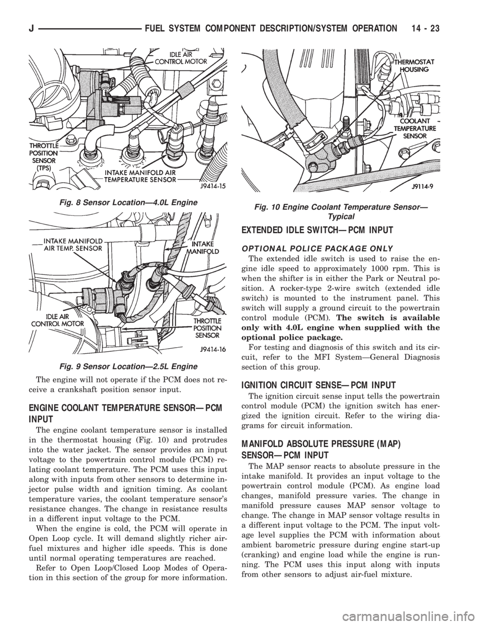
The engine will not operate if the PCM does not re-
ceive a crankshaft position sensor input.
ENGINE COOLANT TEMPERATURE SENSORÐPCM
INPUT
The engine coolant temperature sensor is installed
in the thermostat housing (Fig. 10) and protrudes
into the water jacket. The sensor provides an input
voltage to the powertrain control module (PCM) re-
lating coolant temperature. The PCM uses this input
along with inputs from other sensors to determine in-
jector pulse width and ignition timing. As coolant
temperature varies, the coolant temperature sensor's
resistance changes. The change in resistance results
in a different input voltage to the PCM.
When the engine is cold, the PCM will operate in
Open Loop cycle. It will demand slightly richer air-
fuel mixtures and higher idle speeds. This is done
until normal operating temperatures are reached.
Refer to Open Loop/Closed Loop Modes of Opera-
tion in this section of the group for more information.
EXTENDED IDLE SWITCHÐPCM INPUT
OPTIONAL POLICE PACKAGE ONLY
The extended idle switch is used to raise the en-
gine idle speed to approximately 1000 rpm. This is
when the shifter is in either the Park or Neutral po-
sition. A rocker-type 2-wire switch (extended idle
switch) is mounted to the instrument panel. This
switch will supply a ground circuit to the powertrain
control module (PCM).The switch is available
only with 4.0L engine when supplied with the
optional police package.
For testing and diagnosis of this switch and its cir-
cuit, refer to the MFI SystemÐGeneral Diagnosis
section of this group.
IGNITION CIRCUIT SENSEÐPCM INPUT
The ignition circuit sense input tells the powertrain
control module (PCM) the ignition switch has ener-
gized the ignition circuit. Refer to the wiring dia-
grams for circuit information.
MANIFOLD ABSOLUTE PRESSURE (MAP)
SENSORÐPCM INPUT
The MAP sensor reacts to absolute pressure in the
intake manifold. It provides an input voltage to the
powertrain control module (PCM). As engine load
changes, manifold pressure varies. The change in
manifold pressure causes MAP sensor voltage to
change. The change in MAP sensor voltage results in
a different input voltage to the PCM. The input volt-
age level supplies the PCM with information about
ambient barometric pressure during engine start-up
(cranking) and engine load while the engine is run-
ning. The PCM uses this input along with inputs
from other sensors to adjust air-fuel mixture.
Fig. 8 Sensor LocationÐ4.0L Engine
Fig. 9 Sensor LocationÐ2.5L Engine
Fig. 10 Engine Coolant Temperature SensorÐ
Typical
JFUEL SYSTEM COMPONENT DESCRIPTION/SYSTEM OPERATION 14 - 23
Page 1429 of 2158
DATA LINK CONNECTORÐPCM OUTPUT
Refer to the previous paragraphs on Data Link
ConnectorÐPCM Input for information.
EMR LAMPÐPCM OUTPUT
The EMR (SRI) lamp is not used for the 1995
model year.
FUEL PUMP RELAYÐPCM OUTPUT
The PCM energizes the fuel pump and the oxygen
sensor (O2S) heating element through the fuel pump
relay. Battery voltage is applied to the relay from the
ignition switch. The relay is energized when a
ground is provided by the PCM. Refer to Automatic
Shutdown Relay for additional information.
FUEL INJECTORSÐPCM OUTPUT
Six individual fuel injectors are used with the 4.0L
6-cylinder engine. Four individual fuel injectors are
used with the 2.5L 4-cylinder engine. The injectors
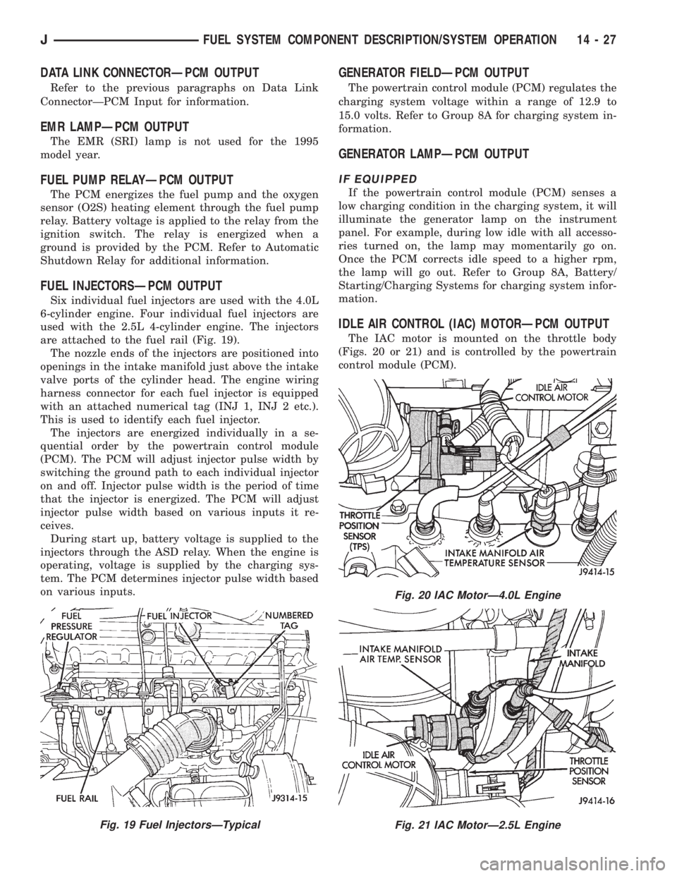
are attached to the fuel rail (Fig. 19).
The nozzle ends of the injectors are positioned into
openings in the intake manifold just above the intake
valve ports of the cylinder head. The engine wiring
harness connector for each fuel injector is equipped
with an attached numerical tag (INJ 1, INJ 2 etc.).
This is used to identify each fuel injector.
The injectors are energized individually in a se-
quential order by the powertrain control module
(PCM). The PCM will adjust injector pulse width by
switching the ground path to each individual injector
on and off. Injector pulse width is the period of time
that the injector is energized. The PCM will adjust
injector pulse width based on various inputs it re-
ceives.
During start up, battery voltage is supplied to the
injectors through the ASD relay. When the engine is
operating, voltage is supplied by the charging sys-
tem. The PCM determines injector pulse width based
on various inputs.
GENERATOR FIELDÐPCM OUTPUT
The powertrain control module (PCM) regulates the
charging system voltage within a range of 12.9 to
15.0 volts. Refer to Group 8A for charging system in-
formation.
GENERATOR LAMPÐPCM OUTPUT
IF EQUIPPED
If the powertrain control module (PCM) senses a
low charging condition in the charging system, it will
illuminate the generator lamp on the instrument
panel. For example, during low idle with all accesso-
ries turned on, the lamp may momentarily go on.
Once the PCM corrects idle speed to a higher rpm,
the lamp will go out. Refer to Group 8A, Battery/
Starting/Charging Systems for charging system infor-
mation.
IDLE AIR CONTROL (IAC) MOTORÐPCM OUTPUT
The IAC motor is mounted on the throttle body
(Figs. 20 or 21) and is controlled by the powertrain
control module (PCM).
Fig. 19 Fuel InjectorsÐTypical
Fig. 20 IAC MotorÐ4.0L Engine
Fig. 21 IAC MotorÐ2.5L Engine
JFUEL SYSTEM COMPONENT DESCRIPTION/SYSTEM OPERATION 14 - 27
Page 1438 of 2158
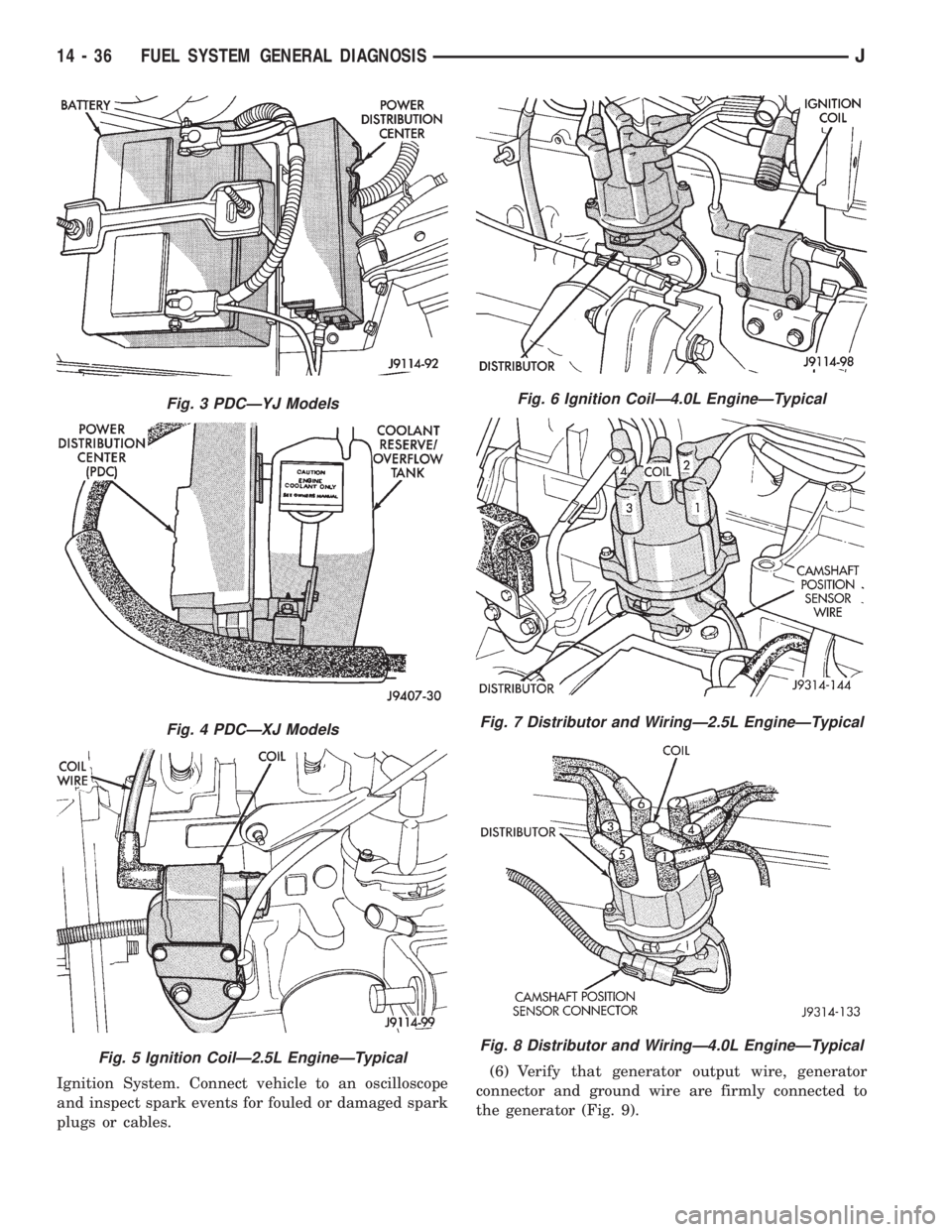
Ignition System. Connect vehicle to an oscilloscope
and inspect spark events for fouled or damaged spark
plugs or cables.(6) Verify that generator output wire, generator
connector and ground wire are firmly connected to
the generator (Fig. 9).
Fig. 3 PDCÐYJ Models
Fig. 4 PDCÐXJ Models
Fig. 5 Ignition CoilÐ2.5L EngineÐTypical
Fig. 6 Ignition CoilÐ4.0L EngineÐTypical
Fig. 7 Distributor and WiringÐ2.5L EngineÐTypical
Fig. 8 Distributor and WiringÐ4.0L EngineÐTypical
14 - 36 FUEL SYSTEM GENERAL DIAGNOSISJ
Page 1439 of 2158
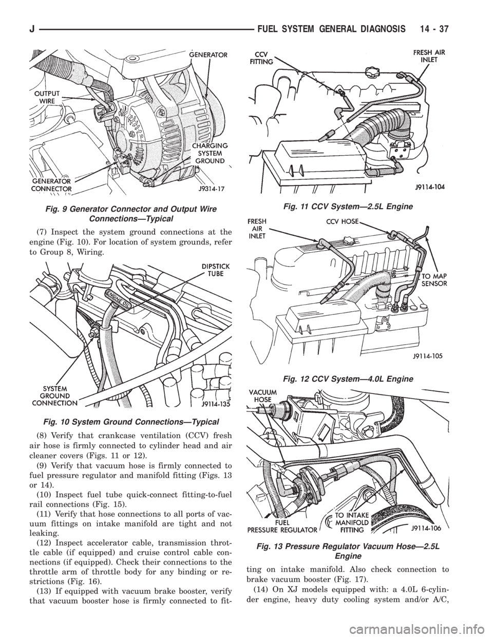
(7) Inspect the system ground connections at the
engine (Fig. 10). For location of system grounds, refer
to Group 8, Wiring.
(8) Verify that crankcase ventilation (CCV) fresh
air hose is firmly connected to cylinder head and air
cleaner covers (Figs. 11 or 12).
(9) Verify that vacuum hose is firmly connected to
fuel pressure regulator and manifold fitting (Figs. 13
or 14).
(10) Inspect fuel tube quick-connect fitting-to-fuel
rail connections (Fig. 15).
(11) Verify that hose connections to all ports of vac-
uum fittings on intake manifold are tight and not
leaking.
(12) Inspect accelerator cable, transmission throt-
tle cable (if equipped) and cruise control cable con-
nections (if equipped). Check their connections to the
throttle arm of throttle body for any binding or re-
strictions (Fig. 16).
(13) If equipped with vacuum brake booster, verify
that vacuum booster hose is firmly connected to fit-ting on intake manifold. Also check connection to
brake vacuum booster (Fig. 17).
(14) On XJ models equipped with: a 4.0L 6-cylin-
der engine, heavy duty cooling system and/or A/C,
Fig. 9 Generator Connector and Output Wire
ConnectionsÐTypical
Fig. 10 System Ground ConnectionsÐTypical
Fig. 11 CCV SystemÐ2.5L Engine
Fig. 12 CCV SystemÐ4.0L Engine
Fig. 13 Pressure Regulator Vacuum HoseÐ2.5L
Engine
JFUEL SYSTEM GENERAL DIAGNOSIS 14 - 37