1995 JEEP YJ wiring
[x] Cancel search: wiringPage 1536 of 2158
(4) From the end of travel, rotate the rotor 2 1/2
full turns in the COUNTER CLOCKWISE direction.
The horn wire should end up at the top and the
squib wire at the bottom (Fig. 9).
(5) Install the steering wheel and air bag module,
refer to Steering Wheel Installation.
COLUMN ASSEMBLY REPLACEMENT
CAUTION: Bumping, jolting and hammering on the
steering column shaft and gear shift tube must be
avoided during all service procedures.
REMOVAL
(1) Make sure the front wheels are in thestraight
aheadposition.
(2) Observe Cautions and disconnect the negative
(ground) cable from the battery.
(3) Disarm airbag, refer to Arming/Disarming Air-
bag in this section.
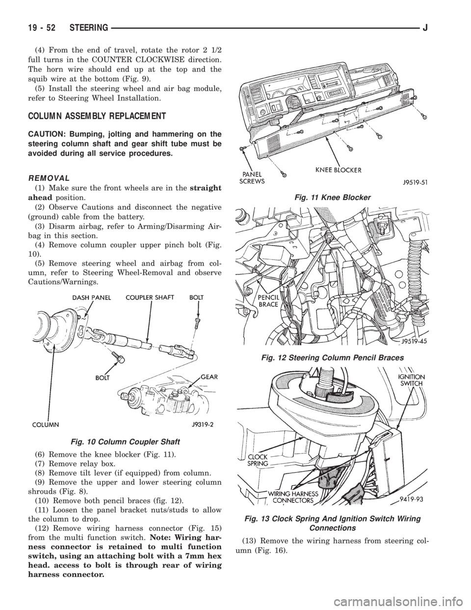
(4) Remove column coupler upper pinch bolt (Fig.
10).
(5) Remove steering wheel and airbag from col-
umn, refer to Steering Wheel-Removal and observe
Cautions/Warnings.
(6) Remove the knee blocker (Fig. 11).
(7) Remove relay box.
(8) Remove tilt lever (if equipped) from column.
(9) Remove the upper and lower steering column
shrouds (Fig. 8).
(10) Remove both pencil braces (fig. 12).
(11) Loosen the panel bracket nuts/studs to allow
the column to drop.
(12) Remove wiring harness connector (Fig. 15)
from the multi function switch.Note: Wiring har-
ness connector is retained to multi function
switch, using an attaching bolt with a 7mm hex
head. access to bolt is through rear of wiring
harness connector.(13) Remove the wiring harness from steering col-
umn (Fig. 16).
Fig. 10 Column Coupler Shaft
Fig. 11 Knee Blocker
Fig. 12 Steering Column Pencil Braces
Fig. 13 Clock Spring And Ignition Switch Wiring
Connections
19 - 52 STEERINGJ
Page 1537 of 2158
(14) Remove the Interlock cable from the steering
column. Refer to Automatic Transmission Shifter/Ig-
nition Interlock in this group.
(15) Remove the column. Use care to avoid damag-
ing the paint or trim.
INSTALLATION
CAUTION: Bumping, jolting and hammering on the
steering column shaft and gear shift tube must be
avoided during all service procedures.
(1) With the front wheels in the straight ahead po-
sition. Align and install the column to coupler.Do
not apply force at the top of the steering col-
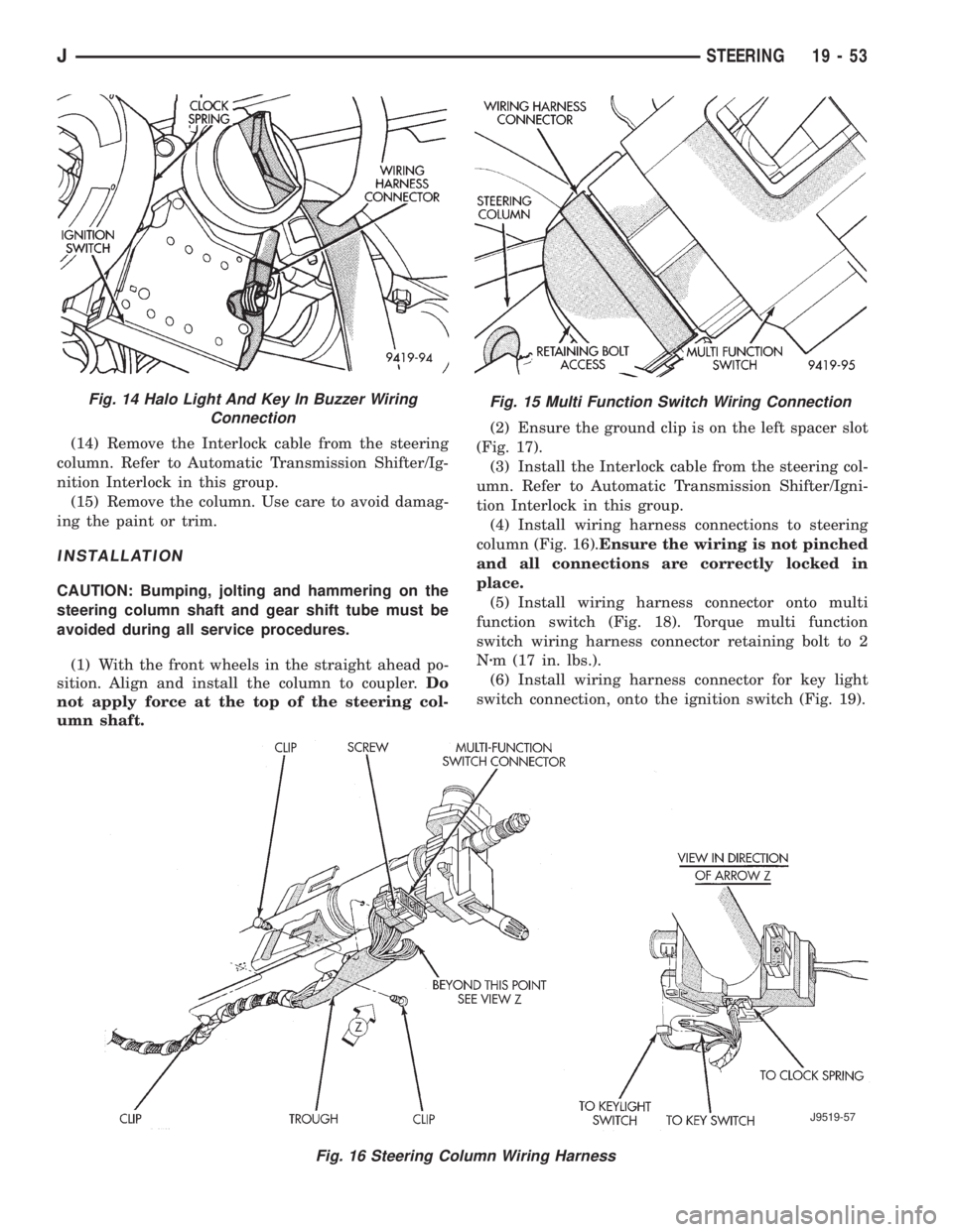
umn shaft.(2) Ensure the ground clip is on the left spacer slot
(Fig. 17).
(3) Install the Interlock cable from the steering col-
umn. Refer to Automatic Transmission Shifter/Igni-
tion Interlock in this group.
(4) Install wiring harness connections to steering
column (Fig. 16).Ensure the wiring is not pinched
and all connections are correctly locked in
place.
(5) Install wiring harness connector onto multi
function switch (Fig. 18). Torque multi function
switch wiring harness connector retaining bolt to 2
Nzm (17 in. lbs.).
(6) Install wiring harness connector for key light
switch connection, onto the ignition switch (Fig. 19).
Fig. 15 Multi Function Switch Wiring Connection
Fig. 16 Steering Column Wiring Harness
J9519-57
Fig. 14 Halo Light And Key In Buzzer Wiring
Connection
JSTEERING 19 - 53
Page 1538 of 2158
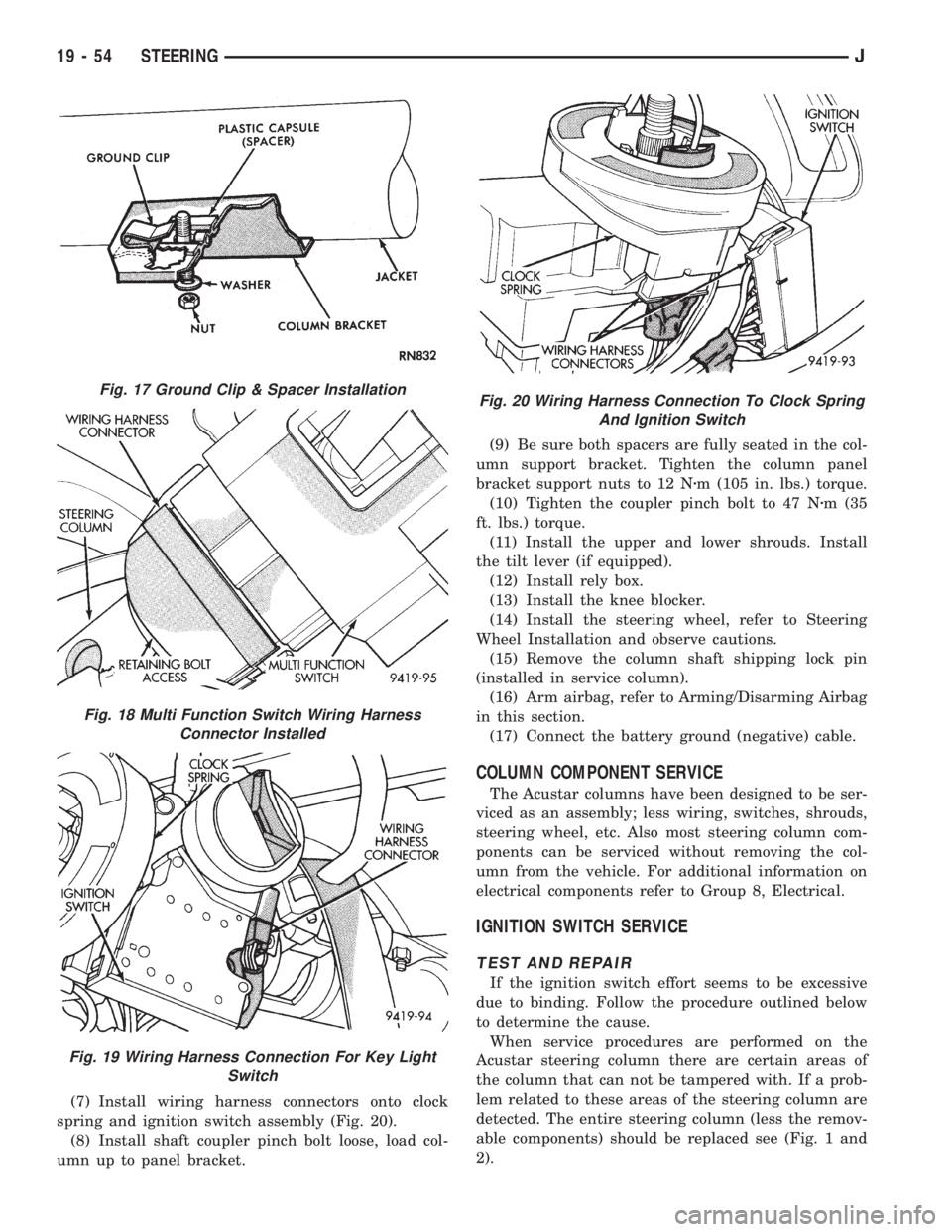
(7) Install wiring harness connectors onto clock
spring and ignition switch assembly (Fig. 20).
(8) Install shaft coupler pinch bolt loose, load col-
umn up to panel bracket.(9) Be sure both spacers are fully seated in the col-
umn support bracket. Tighten the column panel
bracket support nuts to 12 Nzm (105 in. lbs.) torque.
(10) Tighten the coupler pinch bolt to 47 Nzm (35
ft. lbs.) torque.
(11) Install the upper and lower shrouds. Install
the tilt lever (if equipped).
(12) Install rely box.
(13) Install the knee blocker.
(14) Install the steering wheel, refer to Steering
Wheel Installation and observe cautions.
(15) Remove the column shaft shipping lock pin
(installed in service column).
(16) Arm airbag, refer to Arming/Disarming Airbag
in this section.
(17) Connect the battery ground (negative) cable.
COLUMN COMPONENT SERVICE
The Acustar columns have been designed to be ser-
viced as an assembly; less wiring, switches, shrouds,
steering wheel, etc. Also most steering column com-
ponents can be serviced without removing the col-
umn from the vehicle. For additional information on
electrical components refer to Group 8, Electrical.
IGNITION SWITCH SERVICE
TEST AND REPAIR
If the ignition switch effort seems to be excessive
due to binding. Follow the procedure outlined below
to determine the cause.
When service procedures are performed on the
Acustar steering column there are certain areas of
the column that can not be tampered with. If a prob-
lem related to these areas of the steering column are
detected. The entire steering column (less the remov-
able components) should be replaced see (Fig. 1 and
2).
Fig. 17 Ground Clip & Spacer Installation
Fig. 18 Multi Function Switch Wiring Harness
Connector Installed
Fig. 19 Wiring Harness Connection For Key Light
Switch
Fig. 20 Wiring Harness Connection To Clock Spring
And Ignition Switch
19 - 54 STEERINGJ
Page 1671 of 2158
Inspection
Check the sprag shaft for scores and for free move-
ment in the housing and sprag.
Check the sprag and control rod springs for loss of
tension or distortion. Check the square lug on the
sprag for broken edges. Check the lugs on the gover-
nor support (park gear) for broken edges. Replace
any park lock components that are worn or damaged.
Check the knob on the end of the control rod for
nicks, burrs and free turning. Replace the rod if the
knob is grooved, or worn, or if the rod is bent. The
park lock rods used in Chrysler 3-speed transmis-
sions are different lengths. If the rod must be re-
placed, be sure to install the correct length and
shape rod.
COMPONENT INSTALLATION
(1) Install park lock rod on valve body.
(2) Install reaction plug and pin assembly in the
housing and install the snap ring.
(3) Position sprag and spring in housing and in-
stall sprag shaft. Be sure square lug on sprag is fac-
ing park gear and that spring is positioned so it
moves sprag away from park gear.
(4) Install valve body.
(5) Install adapter housing and transfer case.
PARK/NEUTRAL POSITION SWITCH SERVICE
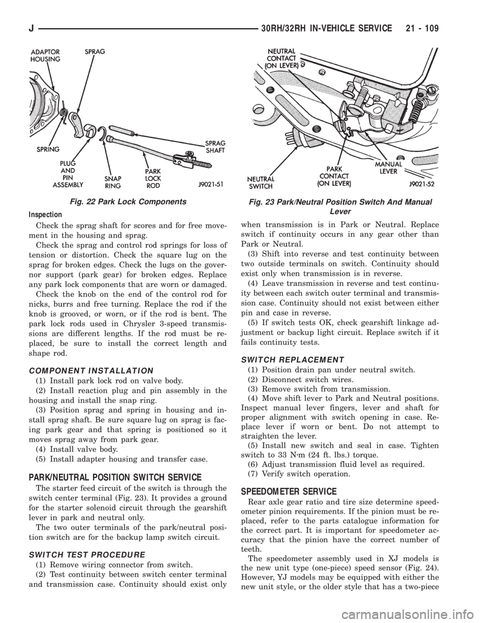
The starter feed circuit of the switch is through the
switch center terminal (Fig. 23). It provides a ground
for the starter solenoid circuit through the gearshift
lever in park and neutral only.
The two outer terminals of the park/neutral posi-
tion switch are for the backup lamp switch circuit.
SWITCH TEST PROCEDURE
(1) Remove wiring connector from switch.
(2) Test continuity between switch center terminal
and transmission case. Continuity should exist onlywhen transmission is in Park or Neutral. Replace
switch if continuity occurs in any gear other than
Park or Neutral.
(3) Shift into reverse and test continuity between
two outside terminals on switch. Continuity should
exist only when transmission is in reverse.
(4) Leave transmission in reverse and test continu-
ity between each switch outer terminal and transmis-
sion case. Continuity should not exist between either
pin and case in reverse.
(5) If switch tests OK, check gearshift linkage ad-
justment or backup light circuit. Replace switch if it
fails continuity tests.
SWITCH REPLACEMENT
(1) Position drain pan under neutral switch.
(2) Disconnect switch wires.
(3) Remove switch from transmission.
(4) Move shift lever to Park and Neutral positions.
Inspect manual lever fingers, lever and shaft for
proper alignment with switch opening in case. Re-
place lever if worn or bent. Do not attempt to
straighten the lever.
(5) Install new switch and seal in case. Tighten
switch to 33 Nzm (24 ft. lbs.) torque.
(6) Adjust transmission fluid level as required.
(7) Verify switch operation.
SPEEDOMETER SERVICE
Rear axle gear ratio and tire size determine speed-
ometer pinion requirements. If the pinion must be re-
placed, refer to the parts catalogue information for
the correct part. It is important for speedometer ac-
curacy that the pinion have the correct number of
teeth.
The speedometer assembly used in XJ models is
the new unit type (one-piece) speed sensor (Fig. 24).
However, YJ models may be equipped with either the
new unit style, or the older style that has a two-piece
Fig. 22 Park Lock ComponentsFig. 23 Park/Neutral Position Switch And Manual
Lever
J30RH/32RH IN-VEHICLE SERVICE 21 - 109
Page 2095 of 2158
HEATING AND AIR CONDITIONING TEST PROCEDURES
INDEX
page page
A/C Compressor Clutch..................... 15
A/C Compressor Clutch Relay................ 15
A/C Compressor Clutch Relay................ 16
Air Conditioning ControlsÐXJ Vehicles......... 15
Air Conditioning ControlsÐYJ Vehicles......... 16
Blower Motor............................ 17
Blower Motor Switch....................... 16Compressor Clutch........................ 16
Fin Sensing Cycling Clutch Switch............. 15
Heater Diagnosis......................... 17
Low-Pressure High-Pressure Cut-Off Switch..... 15
Low-Pressure High-Pressure Cut-Off Switch..... 16
Thermostatic Control....................... 16
AIR CONDITIONING CONTROLSÐXJ VEHICLES
The A/C Compressor Clutch is controlled by several
components: the Pressure Cut-Off Switch, Cycling
Clutch Switch, Clutch Relay and Powertrain Control
Module (PCM).
Powertrain Control Module may delay A/C clutch
engagement up to 30 seconds.
Refer to Group 8W Wiring Diagrams for wiring and
terminals. Use volt ohmmeter to test switches.
A/C COMPRESSOR CLUTCH
The clutch assembly consists of a stationary elec-
tromagnetic coil, hub bearing pulley assembly, and
clutch plate. When the coil is energized the plate is
magnetically engaged with the pulley and turns the
compressor shaft.
A/C COMPRESSOR CLUTCH TEST
(1) Unplug clutch coil connector.
(2) Connect a jumper wire from the battery posi-
tive post to the clutch coil terminal. The clutch
should engage, if not leave jumper wire connected
and go to next step.
(3) Connect a jumper wire from clutch coil frame to
chassis ground. The clutch should engage if not re-
pair clutch coil ground or replace coil.
A/C COMPRESSOR CLUTCH RELAY
The A/C compressor clutch relay controls the 12-
volt source to the A/C clutch. The relay is activated
when the PCM receives a A/C request signal from the
fin-sensed cycling clutch switch. The PCM then sends
a ground signal to the relay. The relay is activated
and sends 12-volts to the clutch coil which energizes
the clutch. The relay is located in the power distribu-
tion center.
COMPRESSOR CLUTCH RELAY TEST
For test procedure refer to Powertrain Diagnostic
Service Manual for A/C clutch relay circuit test.
LOW-PRESSURE HIGH-PRESSURE CUT-OFF
SWITCH
The pressure cut-off switch is located on the filter
drier and is wired in series with compressor clutch.
The switch interrupts the power to the compressor
clutch circuit when the pressure drops to 193 kPa (28
psi) or increases above 3100 to 3375 kPa (450 to 490
psi).
PRESSURE CUT-OFF SWITCH TEST
(1) Verify system has correct refrigerant charge.
(2) Turn ignition switch to RUN, A/C blower switch
to ON and control set to MAX.
(3) Unplug pressure cut-off switch and test feed
circuit from select switch. It should be battery volt-
age if not, repair open to select switch.
(4) Test for continuity between the switch termi-
nals. If continuity is not present recover refrigerant
from the system. Replace switch, evacuate and re-
charge system.
FIN SENSING CYCLING CLUTCH SWITCH
The switch is attached to the evaporator coil with
the temperature sensing probe inserted into the coil
fins. This switch prevents condensate water on the
evaporator coil from freezing. It does this by sending
signals to the PCM to cycling the compressor clutch
on and off.
FIN-SENSED CYCLING CLUTCH SWITCH TEST
Test area ambient temperature should be around
21ÉC (70ÉF) for test.
(1) Verify system has correct refrigerant charge.
(2) Start Engine and turn on A/C.
(3) If the compressor clutch cycles ON and OFF 2
to 3 times per minute the cycling clutch switch is
normal. The ambient temperature should be between
20ÉC-30ÉC (68ÉF-90ÉF). Above 32ÉC (90ÉF) the com-
pressor clutch may stay engaged (non cycling) due to
the high heat load, this condition is normal. If the
compressor clutch fails to engage go to next step.
(4) Disconnect wiring harness connector from
switch. With a volt meter test feed circuit from cut-
JHEATING AND AIR CONDITIONING 24 - 15
Page 2096 of 2158
off switch for battery voltage. If no voltage is present
test pressure cut-off switch. If voltage is present go
to next step.
(5) With ohmmeter test harness connector ground
circuit for continuity to ground. If circuit is open, (no
continuity) repair ground circuit. If circuit test OK
and clutch does not engage refer to Powertrain Diag-
nostic Service Manual for A/C clutch circuit test.
AIR CONDITIONING CONTROLSÐYJ VEHICLES
The air conditioning circuit consists of 3 segments;
battery supply, blower motor and compressor clutch.
The 3 segments have a common connection point at
the blower switch.
The power supply circuit extends from the HTR/
FAN fuse to the blower switch. From the blower
switch, battery feed is routed to the blower motor
and compressor clutch circuit.
Refer to Group 8W Wiring Diagrams for wiring
schematic and terminals. Use volt ohmmeter to test
switches.
COMPRESSOR CLUTCH
The clutch assembly consists of a stationary elec-
tromagnetic coil, hub bearing pulley assembly, and
clutch plate. When the coil is energized the plate is
magnetically engaged with the pulley and turns the
compressor shaft.
COMPRESSOR CLUTCH TEST
(1) Unplug clutch coil connector.
(2) Connect jumper wire from battery positive post
to clutch coil connector. The clutch should engage, if
not leave jumper wire connected and go to next step.
(3) Connect jumper wire from clutch coil frame to
chassis ground. The clutch should engage, if not re-
pair clutch coil ground or replace coil.
A/C COMPRESSOR CLUTCH RELAY
The A/C compressor clutch relay controls the 12-
volt source to the A/C clutch. The relay is activated
when the PCM receives a A/C request signal. The
PCM then sends a ground signal to the relay. The re-
lay is activated and sends 12-volts to the clutch coil
which energizes the clutch. The relay is located in
the power distribution center.
COMPRESSOR CLUTCH RELAY TEST
For test procedure refer to Powertrain Diagnostic
Service Manual for A/C clutch relay circuit test.
LOW-PRESSURE HIGH-PRESSURE CUT-OFF
SWITCH
The pressure cut-off switch is located on the filter
drier and is wired in series with compressor clutch.
The switch interrupts the power to the compressorclutch circuit when the pressure drops to 193 kPa (28
psi) or increases above 3100 to 3375 kPa (450 to 490
psi).
PRESSURE CUT-OFF SWITCH TEST
(1) Turn ignition switch to RUN, A/C blower switch
to ON and control set to MAX.
(2) Unplug pressure cut-off switch connector and
test feed circuit from the thermostatic, should be bat-
tery voltage. If not, proceed to thermostatic control
tests.
(3) Test for continuity between the switch termi-
nals. If continuity is not present recover refrigerant
system, replace switch, evacuate and recharge sys-
tem.
THERMOSTATIC CONTROL
Cycling of the compressor and therefore the tem-
perature of the outlet air is regulated by the thermo-
static control. A thermal sensor extends from the
control to the evaporator housing. When the temper-
ature of the evaporator drops below the set tempera-
ture, the thermostatic control opens the clutch
circuit. The circuit remains open until evaporator
temperature rises above the set temperature.
THERMOSTATIC CONTROL TEST
(1) Turn ignition switch to RUN, A/C blower switch
to ON and thermostatic control set to MAX cool.
(2) Test thermostatic control feed terminal from
blower switch, should be battery voltage. If not re-
pair open from blower switch.
(3) Test thermostatic control output terminal to
pressure cut-out switch, should be battery voltage. If
not, replace thermostatic control.
BLOWER MOTOR SWITCH
The blower switch controls blower motor speed.
The blower motor segment consists of the 3 wires
from the blower switch to the motor. Through the
switch, the 3 wires connect the motor brushes to bat-
tery supply. When connected to battery feed, the sep-
arate brushes provide the 3 blower speeds LO, MED,
and HIGH.
BLOWER MOTOR SWITCH TEST
(1) Turn ignition to RUN position.
(2) Test battery side of fuse for battery voltage. If
not, repair open from ignition switch.
(3) Test A/C blower switch feed circuit from fuse
box should be battery voltage. If not, repair open
from fuse panel.
(4) Test A/C blower switch LO terminal with
blower switch in LO, should be battery voltage. If
not, replace switch.
(5) Test A/C blower switch MED terminal with
blower switch in MED, should be battery voltage. If
not, replace switch.
24 - 16 HEATING AND AIR CONDITIONINGJ
Page 2097 of 2158
(6) Test A/C blower switch HIGH terminal with
blower switch in HIGH, should be battery voltage. If
not, replace switch.
BLOWER MOTOR
The A/C blower motor is attached to the evaporator
housing mounted under the instrument panel. The
motor has a ground wire and 3 wires connect to the
motor brushes. When voltage is applied to the sepa-
rate brushes it provides the 3 blower speeds LO,
MED, and HIGH.
BLOWER MOTOR TEST
Turn ignition switch to RUN for voltage tests and
turn ignition switch to OFF for resistance test.
(1) Test A/C blower motor ground terminal should
be 0 ohms. If not, repair ground circuit.
(2) Test A/C blower motor connector LO terminal
with blower switch in LO, should be battery voltage.
If not repair open from blower switch. If the blower
motor is still inoperative replace motor.
(3) Test A/C blower motor connector MED terminal
with blower switch in MED, should be battery volt-
age. If not repair open from blower switch. If the
blower motor is still inoperative replace motor.
(4) Test A/C blower motor connector HIGH termi-
nal with blower switch in HIGH, should be battery
voltage. If not, repair open from blower switch. If the
blower motor is still inoperative, replace motor.
HEATER DIAGNOSIS
On LHD XJ vehicles a water valve controls coolant
flow to the heater core. The valve is vacuum oper-
ated. When vacuum is applied, the valve opens and
coolant is directed through the heater core and back
to the engine. When the water valve is closed (no
vacuum applied) coolant flow bypasses the heater
core back to the engine.
The heating system receives its battery feed from
the fuse box. On YJ vehicles the feed circuit runs to
the HEATER/OFF switch and then to the BLOWER
switch. On XJ vehicles the feed circuit runs to the
HEAT/MODE switch and then to the BLOWER
switch.
The blower speed is controlled by the blower switch
and blower resistors. With the switch in LO, battery
voltage is supplied to the motor through all of the re-
sistors. The motor runs slowly. When the blower
switch is moved to a higher speed, battery voltage in-
creases to the blower motor which increase its speed.
This is accomplished by bypassing some of the blower
resistors. When the switch is in HI, blower resistors
are bypassed and battery voltage is applied directly
to the blower motor.
The following chart has been developed for quick
reference.
Refer to the Group 8W Wiring Diagrams for com-
plete wiring schematic.
JHEATING AND AIR CONDITIONING 24 - 17
Page 2103 of 2158
COMPONENT SERVICEÐXJ VEHICLES
INDEX
page page
A/C Recirculating Door Vacuum Motor
Replacement........................... 27
Blower Motor Resistors Replacement.......... 31
Blower Motor/Fan Replacement............... 24
Condenser Filter DrierÐ2.5L Engines.......... 27
CondenserÐ4.0L Engines................... 28
Description.............................. 23
Evaporator Coil........................... 30
Evaporator/Blower Housing.................. 29Expansion Valve.......................... 31
Filter DrierÐ4.0L Engines................... 28
Fin Sensing Cycling Clutch Switch............. 31
Heater and A/C Control Replacement.......... 23
Heater Core............................. 26
Heater Housing Replacement................ 26
Heater/Defroster/Instrument Panel Outlet Vacuum
Motor Replacement...................... 26
DESCRIPTION
The Climate Control System combines air condi-
tioning, heating and ventilating capabilities for vehi-
cles equipped with air conditioning. Vehicles without
air conditioning perform heating and ventilating
functions without the air conditioning evaporator.
Both systems consist basically of 2 parts:
²Blower and Air Inlet Assembly
²Heater Core and Air Distribution Assembly
These unit may be removed separately from under
the instrument panel for service.
HEATER AND A/C CONTROL REPLACEMENT
(1) Disconnect negative cable from battery.
(2) Remove the instrument panel bezel attaching
screws and remove the instrument panel bezel (Fig.
1). Bezel is snap fit at locations shown.(3) Remove the radio attaching screws (Fig. 2).
(4) Disconnect the radio electrical connector,
ground lead and antenna lead (Fig. 3).
Fig. 1 Instrument Bezel
Fig. 2 Radio Mounting Screws
Fig. 3 Radio Wiring Harness
JHEATING AND AIR CONDITIONING 24 - 23