1995 JEEP YJ ABS
[x] Cancel search: ABSPage 1297 of 2158
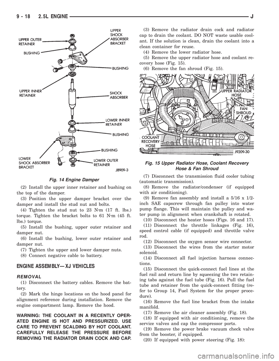
(2) Install the upper inner retainer and bushing on
the top of the damper.
(3) Position the upper damper bracket over the
damper and install the stud nut and bolts.
(4) Tighten the stud nut to 23 Nzm (17 ft. lbs.)
torque. Tighten the bracket bolts to 61 Nzm (45 ft.
lbs.) torque.
(5) Install the bushing, upper outer retainer and
damper nut.
(6) Install the bushing, lower outer retainer and
damper nut.
(7) Tighten the upper and lower damper nuts.
(8) Connect negative cable to battery.
ENGINE ASSEMBLYÐXJ VEHICLES
REMOVAL
(1) Disconnect the battery cables. Remove the bat-
tery.
(2) Mark the hinge locations on the hood panel for
alignment reference during installation. Remove the
engine compartment lamp. Remove the hood.
WARNING: THE COOLANT IN A RECENTLY OPER-
ATED ENGINE IS HOT AND PRESSURIZED. USE
CARE TO PREVENT SCALDING BY HOT COOLANT.
CAREFULLY RELEASE THE PRESSURE BEFORE
REMOVING THE RADIATOR DRAIN COCK AND CAP.(3) Remove the radiator drain cock and radiator
cap to drain the coolant. DO NOT waste usable cool-
ant. If the solution is clean, drain the coolant into a
clean container for reuse.
(4) Remove the lower radiator hose.
(5) Remove the upper radiator hose and coolant re-
covery hose (Fig. 15).
(6) Remove the fan shroud (Fig. 15).
(7) Disconnect the transmission fluid cooler tubing
(automatic transmission).
(8) Remove the radiator/condenser (if equipped
with air conditioning).
(9) Remove fan assembly and install a 5/16 x 1/2-
inch SAE capscrew through fan pulley into water
pump flange. This will maintain the pulley and wa-
ter pump in alignment when crankshaft is rotated.
(10) Disconnect the heater hoses (Figs. 16 and 17).
(11) Disconnect the throttle linkages (Fig. 16),
speed control cable (if equipped) and throttle valve
rod.
(12) Disconnect the oxygen sensor wire connector.
(13) Disconnect the wires from the starter motor
solenoid.
(14) Disconnect all fuel injection harness connec-
tions.
(15) Disconnect the quick-connect fuel lines at the
fuel rail and return line by squeezing the two retain-
ing tabs against the fuel tube (Fig. 16). Pull the fuel
tube and retainer from the quick-connect fitting (re-
fer to Group 14, Fuel System for the proper proce-
dure).
(16) Remove the fuel line bracket from the intake
manifold.
(17) Remove the air cleaner assembly (Fig. 18).
(18) If equipped with air conditioning, remove the
service valves and cap the compressor ports.
(19) Remove the power brake vacuum check valve
from the booster, if equipped.
(20) If equipped with power steering (Fig. 18):
Fig. 14 Engine Damper
Fig. 15 Upper Radiator Hose, Coolant Recovery
Hose & Fan Shroud
9 - 18 2.5L ENGINEJ
Page 1300 of 2158
(7) Disconnect the wires at the starter motor sole-
noid and injection wire harness connector.
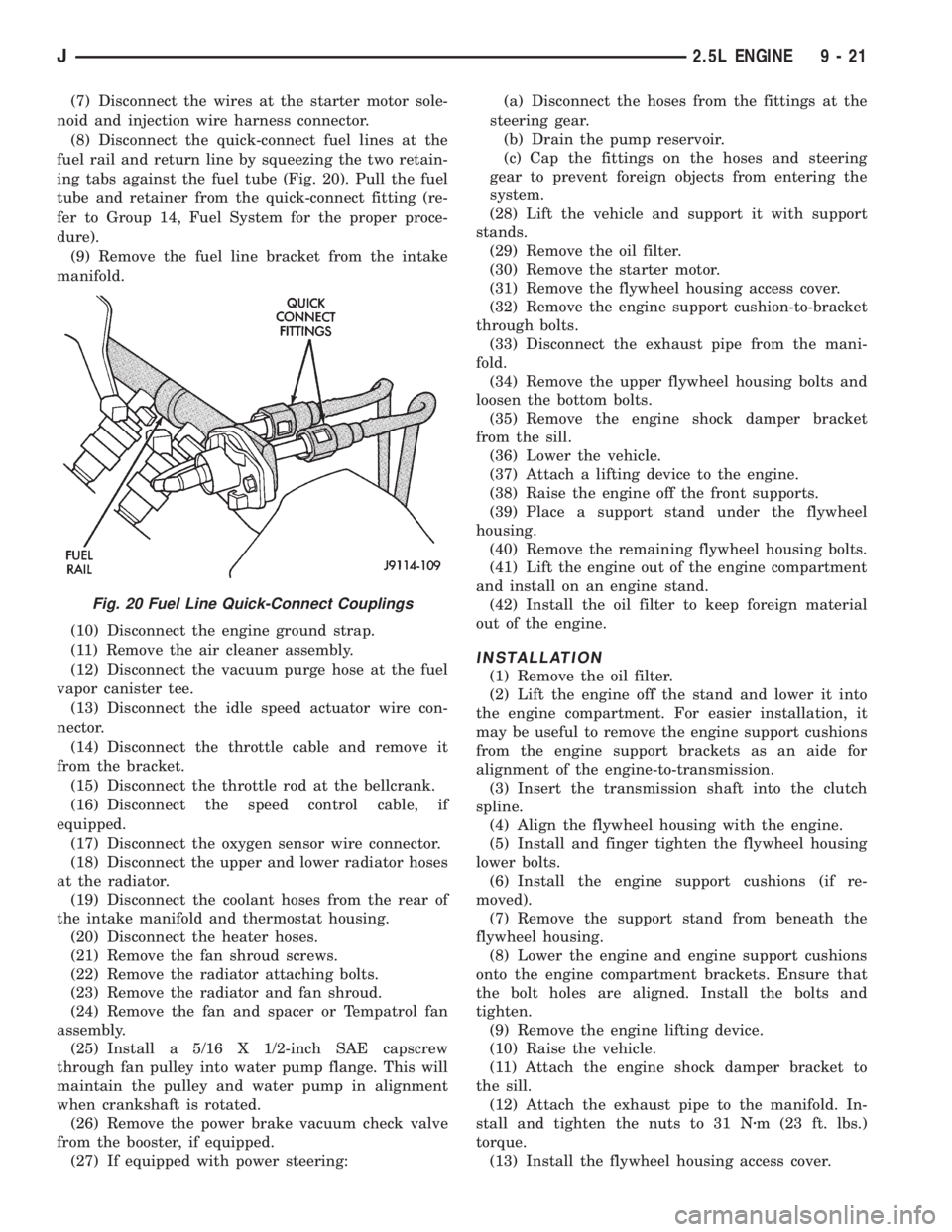
(8) Disconnect the quick-connect fuel lines at the
fuel rail and return line by squeezing the two retain-
ing tabs against the fuel tube (Fig. 20). Pull the fuel
tube and retainer from the quick-connect fitting (re-
fer to Group 14, Fuel System for the proper proce-
dure).
(9) Remove the fuel line bracket from the intake
manifold.
(10) Disconnect the engine ground strap.
(11) Remove the air cleaner assembly.
(12) Disconnect the vacuum purge hose at the fuel
vapor canister tee.
(13) Disconnect the idle speed actuator wire con-
nector.
(14) Disconnect the throttle cable and remove it
from the bracket.
(15) Disconnect the throttle rod at the bellcrank.
(16) Disconnect the speed control cable, if
equipped.
(17) Disconnect the oxygen sensor wire connector.
(18) Disconnect the upper and lower radiator hoses
at the radiator.
(19) Disconnect the coolant hoses from the rear of
the intake manifold and thermostat housing.
(20) Disconnect the heater hoses.
(21) Remove the fan shroud screws.
(22) Remove the radiator attaching bolts.
(23) Remove the radiator and fan shroud.
(24) Remove the fan and spacer or Tempatrol fan
assembly.
(25) Install a 5/16 X 1/2-inch SAE capscrew
through fan pulley into water pump flange. This will
maintain the pulley and water pump in alignment
when crankshaft is rotated.
(26) Remove the power brake vacuum check valve
from the booster, if equipped.
(27) If equipped with power steering:(a) Disconnect the hoses from the fittings at the
steering gear.
(b) Drain the pump reservoir.
(c) Cap the fittings on the hoses and steering
gear to prevent foreign objects from entering the
system.
(28) Lift the vehicle and support it with support
stands.
(29) Remove the oil filter.
(30) Remove the starter motor.
(31) Remove the flywheel housing access cover.
(32) Remove the engine support cushion-to-bracket
through bolts.
(33) Disconnect the exhaust pipe from the mani-
fold.
(34) Remove the upper flywheel housing bolts and
loosen the bottom bolts.
(35) Remove the engine shock damper bracket
from the sill.
(36) Lower the vehicle.
(37) Attach a lifting device to the engine.
(38) Raise the engine off the front supports.
(39) Place a support stand under the flywheel
housing.
(40) Remove the remaining flywheel housing bolts.
(41) Lift the engine out of the engine compartment
and install on an engine stand.
(42) Install the oil filter to keep foreign material
out of the engine.
INSTALLATION
(1) Remove the oil filter.
(2) Lift the engine off the stand and lower it into
the engine compartment. For easier installation, it
may be useful to remove the engine support cushions
from the engine support brackets as an aide for
alignment of the engine-to-transmission.
(3) Insert the transmission shaft into the clutch
spline.
(4) Align the flywheel housing with the engine.
(5) Install and finger tighten the flywheel housing
lower bolts.
(6) Install the engine support cushions (if re-
moved).
(7) Remove the support stand from beneath the
flywheel housing.
(8) Lower the engine and engine support cushions
onto the engine compartment brackets. Ensure that
the bolt holes are aligned. Install the bolts and
tighten.
(9) Remove the engine lifting device.
(10) Raise the vehicle.
(11) Attach the engine shock damper bracket to
the sill.
(12) Attach the exhaust pipe to the manifold. In-
stall and tighten the nuts to 31 Nzm (23 ft. lbs.)
torque.
(13) Install the flywheel housing access cover.
Fig. 20 Fuel Line Quick-Connect Couplings
J2.5L ENGINE 9 - 21
Page 1318 of 2158
OIL PUMP
The positive-displacement gear-type oil pump is
driven by the distributor shaft, which is driven by a
gear on the camshaft. Oil is siphoned into the pump
through an inlet tube and strainer assembly that is
pressed into the pump body.
The pump incorporates a nonadjustable pressure
relief valve to limit maximum pressure to 517 kPa
(75 psi). In the relief position, the valve permits oil to
bypass through a passage in the pump body to the
inlet side of the pump.
Oil pump removal or replacement will not affect
the distributor timing because the distributor drive
gear remains in mesh with the camshaft gear.
REMOVAL
(1) Drain the engine oil.
(2) Remove the oil pan.
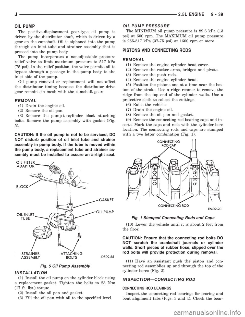
(3) Remove the pump-to-cylinder block attaching
bolts. Remove the pump assembly with gasket (Fig.
5).
CAUTION: If the oil pump is not to be serviced, DO
NOT disturb position of oil inlet tube and strainer
assembly in pump body. If the tube is moved within
the pump body, a replacement tube and strainer as-
sembly must be installed to assure an airtight seal.
INSTALLATION
(1) Install the oil pump on the cylinder block using
a replacement gasket. Tighten the bolts to 23 Nzm
(17 ft. lbs.) torque.
(2) Install the oil pan and gasket.
(3) Fill the oil pan with oil to the specified level.
OIL PUMP PRESSURE
The MINIMUM oil pump pressure is 89.6 kPa (13
psi) at 600 rpm. The MAXIMUM oil pump pressure
is 255-517 kPa (37-75 psi) at 1600 rpm or more.
PISTONS AND CONNECTING RODS
REMOVAL
(1) Remove the engine cylinder head cover.
(2) Remove the rocker arms, bridges and pivots.
(3) Remove the push rods.
(4) Remove the engine cylinder head.
(5) Position the pistons one at a time near the bot-
tom of the stroke. Use a ridge reamer to remove the
ridge from the top end of the cylinder walls. Use a
protective cloth to collect the cuttings.
(6) Raise the vehicle.
(7) Drain the engine oil.
(8) Remove the oil pan and gasket.
(9) Remove the connecting rod bearing caps and in-
serts. Mark the caps and rods with the cylinder bore
location. The connecting rods and caps are stamped
with a two letter combination (Fig. 1).
(10) Lower the vehicle until it is about 2 feet from
the floor.
CAUTION: Ensure that the connecting rod bolts DO
NOT scratch the crankshaft journals or cylinder
walls. Short pieces of rubber hose, slipped over the
rod bolts will provide protection during removal.
(11) Have an assistant push the piston and con-
necting rod assemblies up and through the top of the
cylinder bores (Fig. 2).
INSPECTIONÐCONNECTING ROD
CONNECTING ROD BEARINGS
Inspect the connecting rod bearings for scoring and
bent alignment tabs (Figs. 3 and 4). Check the bear-
Fig. 5 Oil Pump Assembly
Fig. 1 Stamped Connecting Rods and Caps
J2.5L ENGINE 9 - 39
Page 1324 of 2158
CAUTION: Verify that the oil squirt holes in the rods
face the camshaft and that the arrows on the pis-
tons face the front of the engine.
(7) Install the oil pan and gaskets as outlined in
the installation procedure.
(8) Lower the vehicle.
(9) Install the engine cylinder head, push rods,
rocker arms, bridges, pivots and engine cylinder head
cover.
(10) Fill the crankcase with engine oil.
CRANKSHAFT MAIN BEARINGS
REMOVAL
(1) Disconnect negative cable from battery.
(2) Remove the spark plugs.
(3) Raise the vehicle.
(4) Remove the oil pan and oil pump.
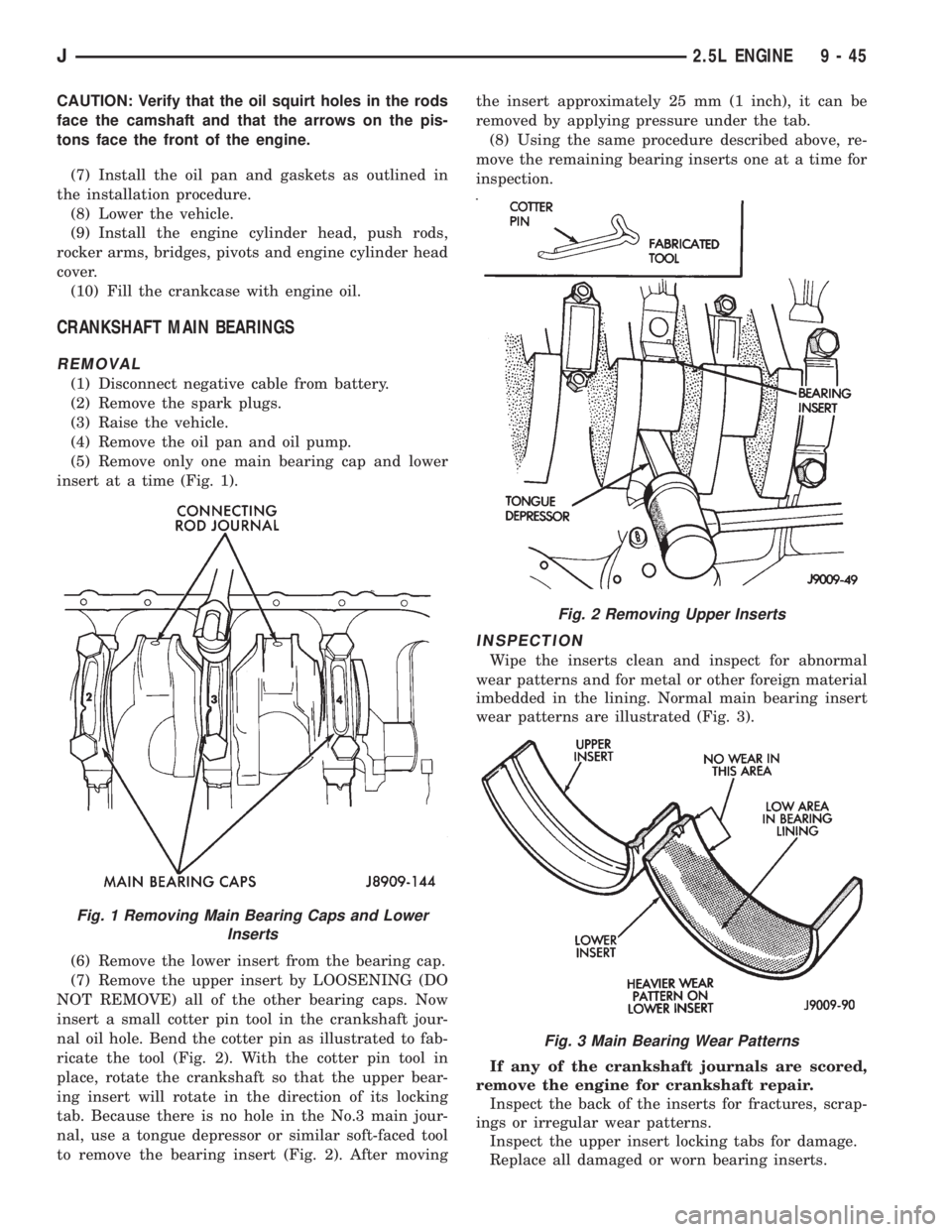
(5) Remove only one main bearing cap and lower
insert at a time (Fig. 1).
(6) Remove the lower insert from the bearing cap.
(7) Remove the upper insert by LOOSENING (DO
NOT REMOVE) all of the other bearing caps. Now
insert a small cotter pin tool in the crankshaft jour-
nal oil hole. Bend the cotter pin as illustrated to fab-
ricate the tool (Fig. 2). With the cotter pin tool in
place, rotate the crankshaft so that the upper bear-
ing insert will rotate in the direction of its locking
tab. Because there is no hole in the No.3 main jour-
nal, use a tongue depressor or similar soft-faced tool
to remove the bearing insert (Fig. 2). After movingthe insert approximately 25 mm (1 inch), it can be
removed by applying pressure under the tab.
(8) Using the same procedure described above, re-
move the remaining bearing inserts one at a time for
inspection.
INSPECTION
Wipe the inserts clean and inspect for abnormal
wear patterns and for metal or other foreign material
imbedded in the lining. Normal main bearing insert
wear patterns are illustrated (Fig. 3).
If any of the crankshaft journals are scored,
remove the engine for crankshaft repair.
Inspect the back of the inserts for fractures, scrap-
ings or irregular wear patterns.
Inspect the upper insert locking tabs for damage.
Replace all damaged or worn bearing inserts.
Fig. 1 Removing Main Bearing Caps and Lower
Inserts
Fig. 2 Removing Upper Inserts
Fig. 3 Main Bearing Wear Patterns
J2.5L ENGINE 9 - 45
Page 1339 of 2158
(6) Remove upper radiator support retaining bolts
and remove radiator support.
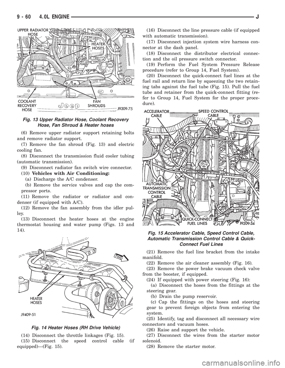
(7) Remove the fan shroud (Fig. 13) and electric
cooling fan.
(8) Disconnect the transmission fluid cooler tubing
(automatic transmission).
(9) Disconnect radiator fan switch wire connector.
(10)Vehicles with Air Conditioning:
(a) Discharge the A/C condenser.
(b) Remove the service valves and cap the com-
pressor ports.
(11) Remove the radiator or radiator and con-
denser (if equipped with A/C).
(12) Remove the fan assembly from the idler pul-
ley.
(13) Disconnect the heater hoses at the engine
thermostat housing and water pump (Figs. 13 and
14).
(14) Disconnect the throttle linkages (Fig. 15).
(15) Disconnect the speed control cable (if
equipped)Ð(Fig. 15).(16) Disconnect the line pressure cable (if equipped
with automatic transmission).
(17) Disconnect injection system wire harness con-
nector at the dash panel.
(18) Disconnect the distributor electrical connec-
tion and the oil pressure switch connector.
(19) Perform the Fuel System Pressure Release
procedure (refer to Group 14, Fuel System).
(20) Disconnect the quick-connect fuel lines at the
fuel rail and return line by squeezing the two retain-
ing tabs against the fuel tube (Fig. 15). Pull the fuel
tube and retainer from the quick-connect fitting (re-
fer to Group 14, Fuel System for the proper proce-
dure).
(21) Remove the fuel line bracket from the intake
manifold.
(22) Remove the air cleaner assembly (Fig. 16).
(23) Remove the power brake vacuum check valve
from the booster, if equipped.
(24) If equipped with power steering (Fig. 16):
(a) Disconnect the hoses from the fittings at the
steering gear.
(b) Drain the pump reservoir.
(c) Cap the fittings on the hoses and steering
gear to prevent foreign objects from entering the
system.
(25) Identify, tag and disconnect all necessary wire
connectors and vacuum hoses.
(26) Raise and support the vehicle.
(27) Disconnect the wires from the starter motor
solenoid.
(28) Remove the starter motor.
Fig. 13 Upper Radiator Hose, Coolant Recovery
Hose, Fan Shroud & Heater hoses
Fig. 14 Heater Hoses (RH Drive Vehicle)
Fig. 15 Accelerator Cable, Speed Control Cable,
Automatic Transmission Control Cable & Quick-
Connect Fuel Lines
9 - 60 4.0L ENGINEJ
Page 1341 of 2158
(26) Connect the speed control cable, if equipped.
(27) Connect the throttle cable linkages.
(28) Connect the heater hoses at the engine ther-
mostat housing and water pump.
(29) Install the fan assembly to the idler pulley.
(30) Install the radiator or radiator and condenser
(if equipped with A/C).
(31) Connect the service valves to the A/C compres-
sor ports, if equipped with A/C.
(32) Charge the air conditioner system.
(33) Connect radiator fan switch wire.
(34) Connect automatic transmission fluid cooler
lines, if equipped.
(35) Install the fan shroud, electric cooling fan and
radiator and condenser (if equipped with A/C).
(36) Install upper radiator support.
(37) Connect the upper radiator hose.
(38) Connect the lower radiator hose.
(39) Fill the cooling system with reusable coolant
and/or new coolant.
(40) Align the hood to the scribe marks. Install the
hood.
(41) Connect the vacuum harness connector.
(a) Firmly push the connectors together ensuring
that the retaining tabs are engaged.
(b) Insert the vacuum connector assembly into
the retaining bracket on the intake manifold.
(42) Install the air cleaner assembly.
(43) Install the battery and connect the battery ca-
ble.
WARNING: USE EXTREME CAUTION WHEN THE
ENGINE IS OPERATING. DO NOT STAND IN A DI-
RECT LINE WITH THE FAN. DO NOT PUT YOUR
HANDS NEAR THE PULLEYS, BELTS OR FAN. DO
NOT WEAR LOOSE CLOTHING.
(44) Start the engine, inspect for leaks and correct
the fluid levels, as necessary.
ENGINE ASSEMBLYÐYJ VEHICLES
REMOVAL
(1) Place a protective cloth over the windshield
frame. Raise the hood and rest it on the windshield
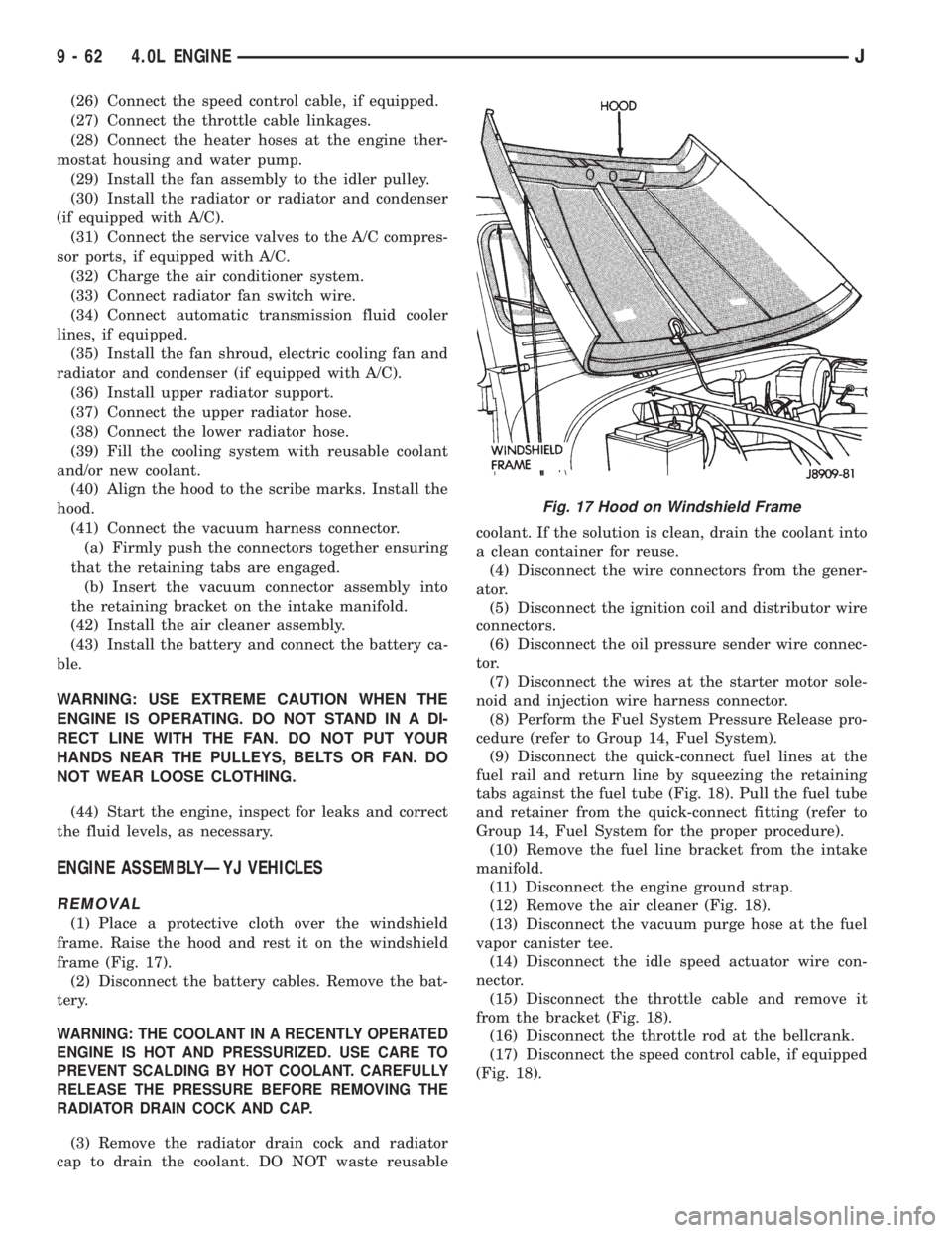
frame (Fig. 17).
(2) Disconnect the battery cables. Remove the bat-
tery.
WARNING: THE COOLANT IN A RECENTLY OPERATED
ENGINE IS HOT AND PRESSURIZED. USE CARE TO
PREVENT SCALDING BY HOT COOLANT. CAREFULLY
RELEASE THE PRESSURE BEFORE REMOVING THE
RADIATOR DRAIN COCK AND CAP.
(3) Remove the radiator drain cock and radiator
cap to drain the coolant. DO NOT waste reusablecoolant. If the solution is clean, drain the coolant into
a clean container for reuse.
(4) Disconnect the wire connectors from the gener-
ator.
(5) Disconnect the ignition coil and distributor wire
connectors.
(6) Disconnect the oil pressure sender wire connec-
tor.
(7) Disconnect the wires at the starter motor sole-
noid and injection wire harness connector.
(8) Perform the Fuel System Pressure Release pro-
cedure (refer to Group 14, Fuel System).
(9) Disconnect the quick-connect fuel lines at the
fuel rail and return line by squeezing the retaining
tabs against the fuel tube (Fig. 18). Pull the fuel tube
and retainer from the quick-connect fitting (refer to
Group 14, Fuel System for the proper procedure).
(10) Remove the fuel line bracket from the intake
manifold.
(11) Disconnect the engine ground strap.
(12) Remove the air cleaner (Fig. 18).
(13) Disconnect the vacuum purge hose at the fuel
vapor canister tee.
(14) Disconnect the idle speed actuator wire con-
nector.
(15) Disconnect the throttle cable and remove it
from the bracket (Fig. 18).
(16) Disconnect the throttle rod at the bellcrank.
(17) Disconnect the speed control cable, if equipped
(Fig. 18).
Fig. 17 Hood on Windshield Frame
9 - 62 4.0L ENGINEJ
Page 1360 of 2158
OIL PUMP
A gear-type oil pump is mounted at the underside
of the cylinder block opposite the No.4 main bearing.
The pump incorporates a nonadjustable pressure
relief valve to limit maximum pressure to 517 kPa
(75 psi). In the relief position, the valve permits oil to
bypass through a passage in the pump body to the
inlet side of the pump.
Oil pump removal or replacement will not affect
the distributor timing because the distributor drive
gear remains in mesh with the camshaft gear.
REMOVAL
(1) Drain the engine oil.
(2) Remove the oil pan.
(3) Remove the pump-to-cylinder block attaching
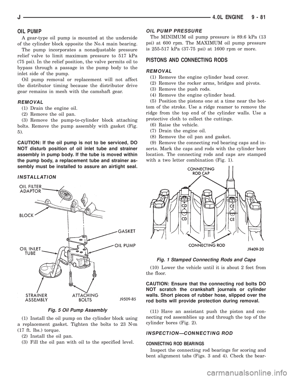
bolts. Remove the pump assembly with gasket (Fig.
5).
CAUTION: If the oil pump is not to be serviced, DO
NOT disturb position of oil inlet tube and strainer
assembly in pump body. If the tube is moved within
the pump body, a replacement tube and strainer as-
sembly must be installed to assure an airtight seal.
INSTALLATION
(1) Install the oil pump on the cylinder block using
a replacement gasket. Tighten the bolts to 23 Nzm
(17 ft. lbs.) torque.
(2) Install the oil pan.
(3) Fill the oil pan with oil to the specified level.
OIL PUMP PRESSURE
The MINIMUM oil pump pressure is 89.6 kPa (13
psi) at 600 rpm. The MAXIMUM oil pump pressure
is 255-517 kPa (37-75 psi) at 1600 rpm or more.
PISTONS AND CONNECTING RODS
REMOVAL
(1) Remove the engine cylinder head cover.
(2) Remove the rocker arms, bridges and pivots.
(3) Remove the push rods.
(4) Remove the engine cylinder head.
(5) Position the pistons one at a time near the bot-
tom of the stroke. Use a ridge reamer to remove the
ridge from the top end of the cylinder walls. Use a
protective cloth to collect the cuttings.
(6) Raise the vehicle.
(7) Drain the engine oil.
(8) Remove the oil pan and gasket.
(9) Remove the connecting rod bearing caps and in-
serts. Mark the caps and rods with the cylinder bore
location. The connecting rods and caps are stamped
with a two letter combination (Fig. 1).
(10) Lower the vehicle until it is about 2 feet from
the floor.
CAUTION: Ensure that the connecting rod bolts DO
NOT scratch the crankshaft journals or cylinder
walls. Short pieces of rubber hose, slipped over the
rod bolts will provide protection during removal.
(11) Have an assistant push the piston and con-
necting rod assemblies up and through the top of the
cylinder bores (Fig. 2).
INSPECTIONÐCONNECTING ROD
CONNECTING ROD BEARINGS
Inspect the connecting rod bearings for scoring and
bent alignment tabs (Figs. 3 and 4). Check the bear-
Fig. 5 Oil Pump Assembly
Fig. 1 Stamped Connecting Rods and Caps
J4.0L ENGINE 9 - 81
Page 1366 of 2158
(8) Lower the vehicle.
(9) Install the engine cylinder head, push rods,
rocker arms, bridges, pivots and engine cylinder head
cover.
(10) Fill the crankcase with engine oil.
CRANKSHAFT MAIN BEARINGS
REMOVAL
(1) Disconnect negative cable from battery.
(2) Remove the spark plugs.
(3) Raise the vehicle.
(4) Remove the oil pan and oil pump.
(5) Remove only one main bearing cap and lower
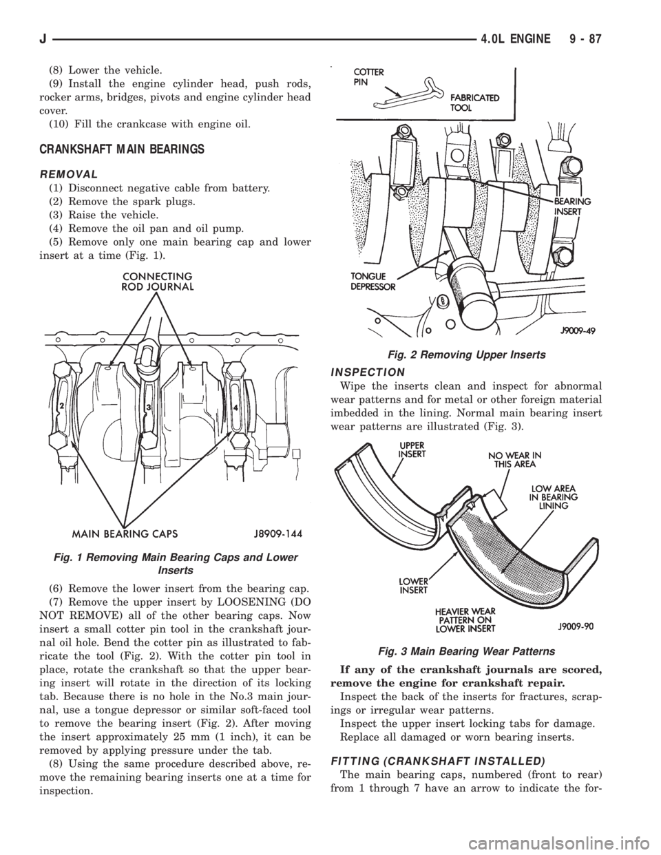
insert at a time (Fig. 1).
(6) Remove the lower insert from the bearing cap.
(7) Remove the upper insert by LOOSENING (DO
NOT REMOVE) all of the other bearing caps. Now
insert a small cotter pin tool in the crankshaft jour-
nal oil hole. Bend the cotter pin as illustrated to fab-
ricate the tool (Fig. 2). With the cotter pin tool in
place, rotate the crankshaft so that the upper bear-
ing insert will rotate in the direction of its locking
tab. Because there is no hole in the No.3 main jour-
nal, use a tongue depressor or similar soft-faced tool
to remove the bearing insert (Fig. 2). After moving
the insert approximately 25 mm (1 inch), it can be
removed by applying pressure under the tab.
(8) Using the same procedure described above, re-
move the remaining bearing inserts one at a time for
inspection.
INSPECTION
Wipe the inserts clean and inspect for abnormal
wear patterns and for metal or other foreign material
imbedded in the lining. Normal main bearing insert
wear patterns are illustrated (Fig. 3).
If any of the crankshaft journals are scored,
remove the engine for crankshaft repair.
Inspect the back of the inserts for fractures, scrap-
ings or irregular wear patterns.
Inspect the upper insert locking tabs for damage.
Replace all damaged or worn bearing inserts.
FITTING (CRANKSHAFT INSTALLED)
The main bearing caps, numbered (front to rear)
from 1 through 7 have an arrow to indicate the for-
Fig. 1 Removing Main Bearing Caps and Lower
Inserts
Fig. 2 Removing Upper Inserts
Fig. 3 Main Bearing Wear Patterns
J4.0L ENGINE 9 - 87