1995 JEEP YJ ABS
[x] Cancel search: ABSPage 1556 of 2158
(9) Install the shift tube thrust washer and the re-
tainer plate snap ring.
(10) Install the lower bearing in the steering col-
umn.
(11) Position the shift gate in the steering column
support. Install the attaching screws.
(12) Position the support in the steering column.
(13) Install all support attaching screws finger-
tight. Next, tighten the screws alternately and evenly
to7Nzm (60 in. lbs.) torque.
(14) Install the remote rod in the support. Route
the rod through the upper end of the shroud and in-
sert it into the rod slot located in the support.
(15) Install the dimmer switch and ignition switch.
(16) Install the steering shaft in the steering col-
umn.
(17) Install replacement races and bearings in the
key/lock cylinder, if removed.Ensure that the bear-
ings are lubricated with chassis lubricant be-
fore installation.
(18) Install the lock shoes, the lock shoe springs
and the lock shoe pin the key/lock cylinder housing.
Use a 4.5-mm (0.18-in) diameter rod to align the
shoes and the pin during installation.
(19) Install the tilt-release lever, the lever spring
and the lever pin in the key/lock cylinder housing.
Insert a wedge between the housing and the lever to
relieve the spring tension. This will allow easier re-
lease lever pin installation.
(20) Install the lock bolt in the key/lock cylinder
housing and engage it in the lock sector cam surface.
(21) Install the lock rack, the rack preload spring
and a replacement shim in the key/lock cylinder
housing. Align and mate the square block tooth on
the lock rack and the lock sector.
(22) Install the lock spring and the spring retain-
ing screw. Tighten the screw to 4 Nzm (35 in. lbs.)
torque.
(23) Align and install the assembled key/lock cylin-
der housing on the support. Retain the lock shoes in
the disengaged position for easier housing installa-
tion.
(24) Align the pivot pin holes in the housing with
those in the support. Insert the pivot pins.Press the
housing firmly downward when inserting the
pivot pins. This prevents damaging the holes in
the support.When the pivot pins are within both
the housing and the support holes, seat them fully
with a punch and a hammer.
(25) Insert tilt-release lever in key/lock cylinder
housing and place housing in the full-upward tilt po-
sition.
(26) Lubricate the tilt spring guide and the tilt
spring liberally with chassis lubricant and position
the spring on the guide.
(27) Insert the tilt spring guide and the spring into
the key/lock cylinder housing. Install the guide re-tainer over the spring. Engage the retainer lock tabs
with the housing lugs by pressing the retainer down-
ward and turning clockwise with a screwdriver.
(28) Place the cover on the key/lock cylinder hous-
ing. Align and install the cover retaining screws.
Tighten the screws to 7 Nzm (60 in. lbs.) torque.
(29) Install the gear selector indicator lamp mount-
ing bracket screw.
(30) Install the gear selector indicator cover and
retaining screws.
(31) Route the dimmer switch wire harness and
gear selector indicator down through the steering col-
umn.
(32) To install ignition switch lock, turn the key to
the LOCK position and remove the key. This will
cause the buzzer operating lever to retract in the
key/lock cylinder. Now insert the key/lock cylinder
into the housing far enough to contact the drive
shaft. Force it inward and move the ignition switch
actuator rod up and down to align the components.
When the components align, the key/lock cylinder
will move inward and the spring-loaded retainer will
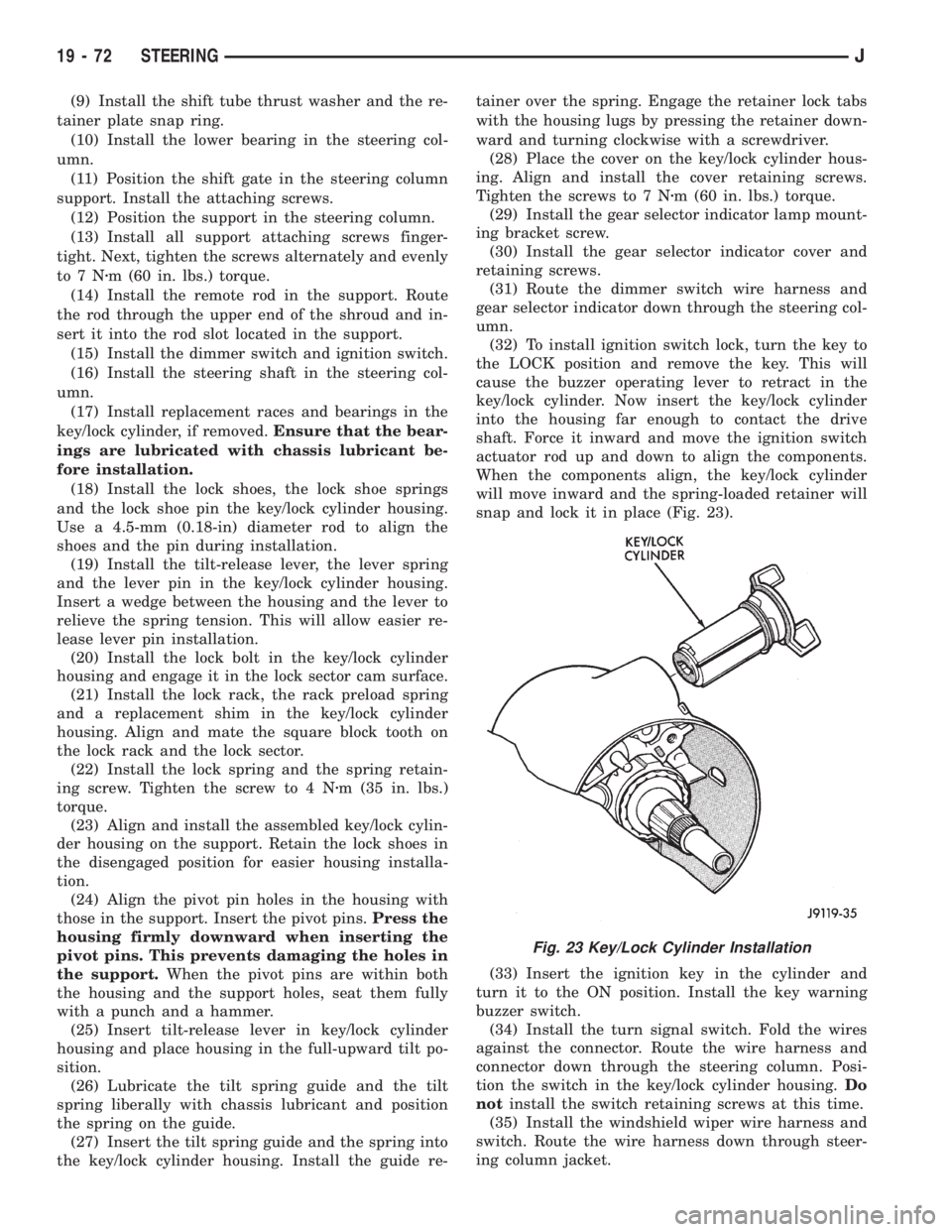
snap and lock it in place (Fig. 23).
(33) Insert the ignition key in the cylinder and
turn it to the ON position. Install the key warning
buzzer switch.
(34) Install the turn signal switch. Fold the wires
against the connector. Route the wire harness and
connector down through the steering column. Posi-
tion the switch in the key/lock cylinder housing.Do
notinstall the switch retaining screws at this time.
(35) Install the windshield wiper wire harness and
switch. Route the wire harness down through steer-
ing column jacket.
Fig. 23 Key/Lock Cylinder Installation
19 - 72 STEERINGJ
Page 1674 of 2158
Early production models will have the type 2 fit-
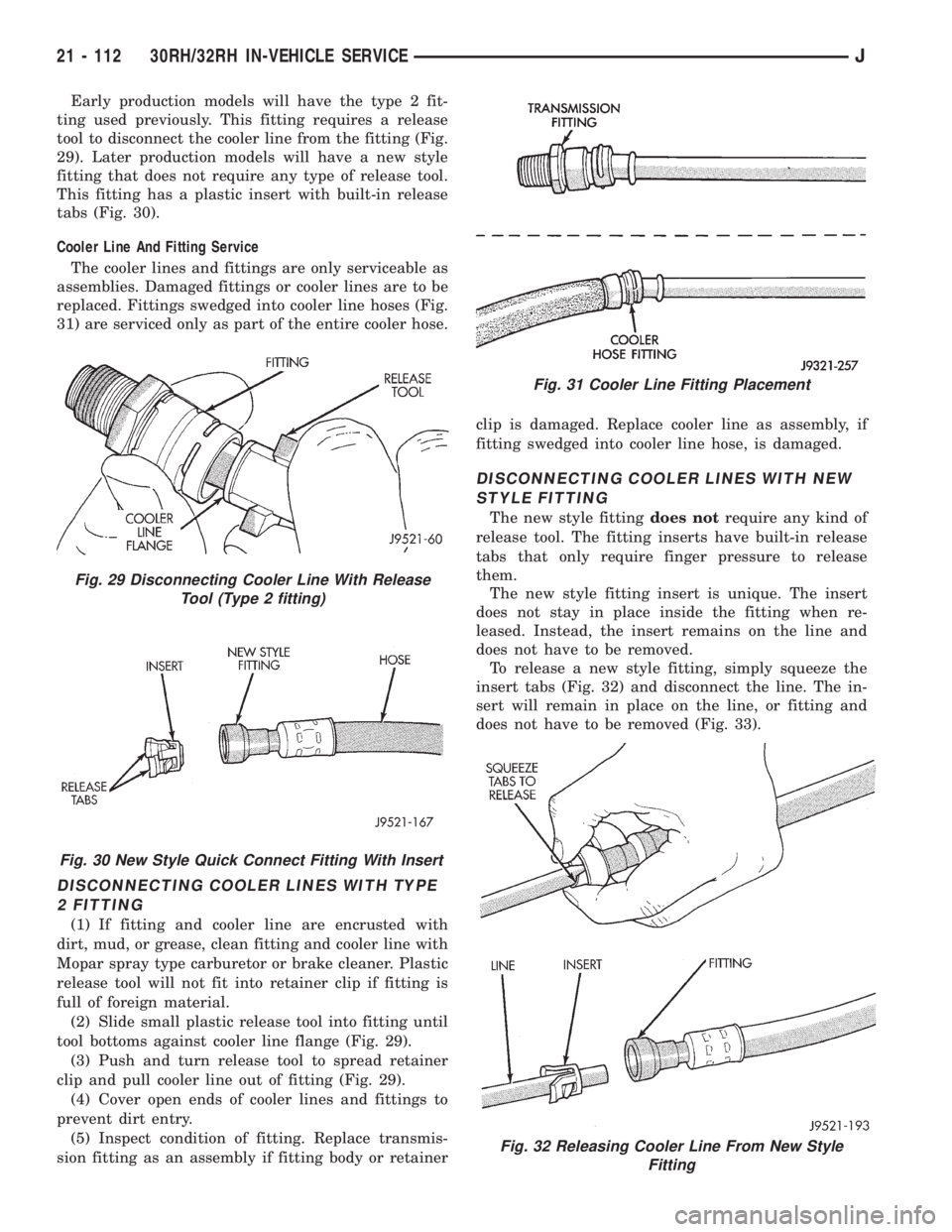
ting used previously. This fitting requires a release
tool to disconnect the cooler line from the fitting (Fig.
29). Later production models will have a new style
fitting that does not require any type of release tool.
This fitting has a plastic insert with built-in release
tabs (Fig. 30).
Cooler Line And Fitting Service
The cooler lines and fittings are only serviceable as
assemblies. Damaged fittings or cooler lines are to be
replaced. Fittings swedged into cooler line hoses (Fig.
31) are serviced only as part of the entire cooler hose.
DISCONNECTING COOLER LINES WITH TYPE
2 FITTING
(1) If fitting and cooler line are encrusted with
dirt, mud, or grease, clean fitting and cooler line with
Mopar spray type carburetor or brake cleaner. Plastic
release tool will not fit into retainer clip if fitting is
full of foreign material.
(2) Slide small plastic release tool into fitting until
tool bottoms against cooler line flange (Fig. 29).
(3) Push and turn release tool to spread retainer
clip and pull cooler line out of fitting (Fig. 29).
(4) Cover open ends of cooler lines and fittings to
prevent dirt entry.
(5) Inspect condition of fitting. Replace transmis-
sion fitting as an assembly if fitting body or retainerclip is damaged. Replace cooler line as assembly, if
fitting swedged into cooler line hose, is damaged.
DISCONNECTING COOLER LINES WITH NEW
STYLE FITTING
The new style fittingdoes notrequire any kind of
release tool. The fitting inserts have built-in release
tabs that only require finger pressure to release
them.
The new style fitting insert is unique. The insert
does not stay in place inside the fitting when re-
leased. Instead, the insert remains on the line and
does not have to be removed.
To release a new style fitting, simply squeeze the
insert tabs (Fig. 32) and disconnect the line. The in-
sert will remain in place on the line, or fitting and
does not have to be removed (Fig. 33).
Fig. 30 New Style Quick Connect Fitting With Insert
Fig. 29 Disconnecting Cooler Line With Release
Tool (Type 2 fitting)
Fig. 31 Cooler Line Fitting Placement
Fig. 32 Releasing Cooler Line From New Style
Fitting
21 - 112 30RH/32RH IN-VEHICLE SERVICEJ
Page 1675 of 2158
CONNECTING COOLER LINES AND FITTINGS
(ALL TYPES)
(1) Wipe cooler line and fitting clean with shop
towel.
(2) Insert cooler line into fitting. Then push line
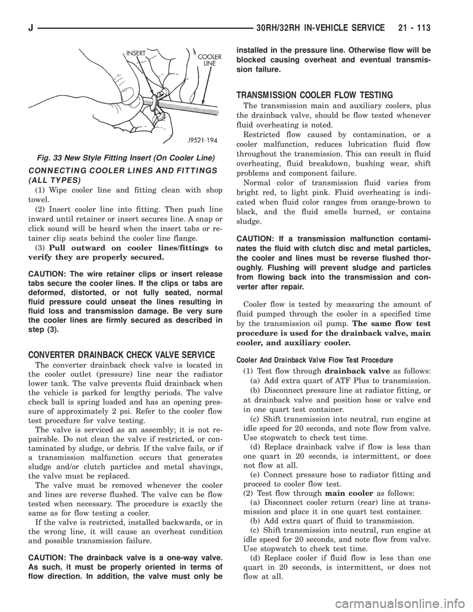
inward until retainer or insert secures line. A snap or
click sound will be heard when the insert tabs or re-
tainer clip seats behind the cooler line flange.
(3)Pull outward on cooler lines/fittings to
verify they are properly secured.
CAUTION: The wire retainer clips or insert release
tabs secure the cooler lines. If the clips or tabs are
deformed, distorted, or not fully seated, normal
fluid pressure could unseat the lines resulting in
fluid loss and transmission damage. Be very sure
the cooler lines are firmly secured as described in
step (3).
CONVERTER DRAINBACK CHECK VALVE SERVICE
The converter drainback check valve is located in
the cooler outlet (pressure) line near the radiator
lower tank. The valve prevents fluid drainback when
the vehicle is parked for lengthy periods. The valve
check ball is spring loaded and has an opening pres-
sure of approximately 2 psi. Refer to the cooler flow
test procedure for valve testing.
The valve is serviced as an assembly; it is not re-
pairable. Do not clean the valve if restricted, or con-
taminated by sludge, or debris. If the valve fails, or if
a transmission malfunction occurs that generates
sludge and/or clutch particles and metal shavings,
the valve must be replaced.
The valve must be removed whenever the cooler
and lines are reverse flushed. The valve can be flow
tested when necessary. The procedure is exactly the
same as for flow testing a cooler.
If the valve is restricted, installed backwards, or in
the wrong line, it will cause an overheat condition
and possible transmission failure.
CAUTION: The drainback valve is a one-way valve.
As such, it must be properly oriented in terms of
flow direction. In addition, the valve must only beinstalled in the pressure line. Otherwise flow will be
blocked causing overheat and eventual transmis-
sion failure.
TRANSMISSION COOLER FLOW TESTING
The transmission main and auxiliary coolers, plus
the drainback valve, should be flow tested whenever
fluid overheating is noted.
Restricted flow caused by contamination, or a
cooler malfunction, reduces lubrication fluid flow
throughout the transmission. This can result in fluid
overheating, fluid breakdown, bushing wear, shift
problems and component failure.
Normal color of transmission fluid varies from
bright red, to light pink. Fluid overheating is indi-
cated when fluid color ranges from orange-brown to
black, and the fluid smells burned, or contains
sludge.
CAUTION: If a transmission malfunction contami-
nates the fluid with clutch disc and metal particles,
the cooler and lines must be reverse flushed thor-
oughly. Flushing will prevent sludge and particles
from flowing back into the transmission and con-
verter after repair.
Cooler flow is tested by measuring the amount of
fluid pumped through the cooler in a specified time
by the transmission oil pump.The same flow test
procedure is used for the drainback valve, main
cooler, and auxiliary cooler.
Cooler And Drainback Valve Flow Test Procedure
(1) Test flow throughdrainback valveas follows:
(a) Add extra quart of ATF Plus to transmission.
(b) Disconnect pressure line at radiator fitting, or
at drainback valve and position hose or valve end
in one quart test container.
(c) Shift transmission into neutral, run engine at
idle speed for 20 seconds, and note flow from valve.
Use stopwatch to check test time.
(d) Replace drainback valve if flow is less than
one quart in 20 seconds, is intermittent, or does
not flow at all.
(e) Connect pressure hose to radiator fitting and
proceed to cooler flow test.
(2) Test flow throughmain cooleras follows:
(a) Disconnect cooler return (rear) line at trans-
mission and place it in one quart test container.
(b) Add extra quart of fluid to transmission.
(c) Shift transmission into neutral, run engine at
idle speed for 20 seconds, and note flow from valve.
Use stopwatch to check test time.
(d) Replace cooler if fluid flow is less than one
quart in 20 seconds, is intermittent, or does not
flow at all.
Fig. 33 New Style Fitting Insert (On Cooler Line)
J30RH/32RH IN-VEHICLE SERVICE 21 - 113
Page 1698 of 2158
Replace the clutch discs if warped, worn, scored,
burned or charred, or if the facing is flaking off. Re-
place the steel plates if heavily scored, warped, or
broken. Be sure the driving lugs on the plates are in
good condition. The lugs must not be bent, cracked or
damaged in any way.
Replace the clutch spring and spring retainer if ei-
ther is distorted, warped or broken.
Check the lug grooves in the clutch retainer. The
steel plates should slide freely in the slots. Replace
the retainer if the grooves are worn or damaged.
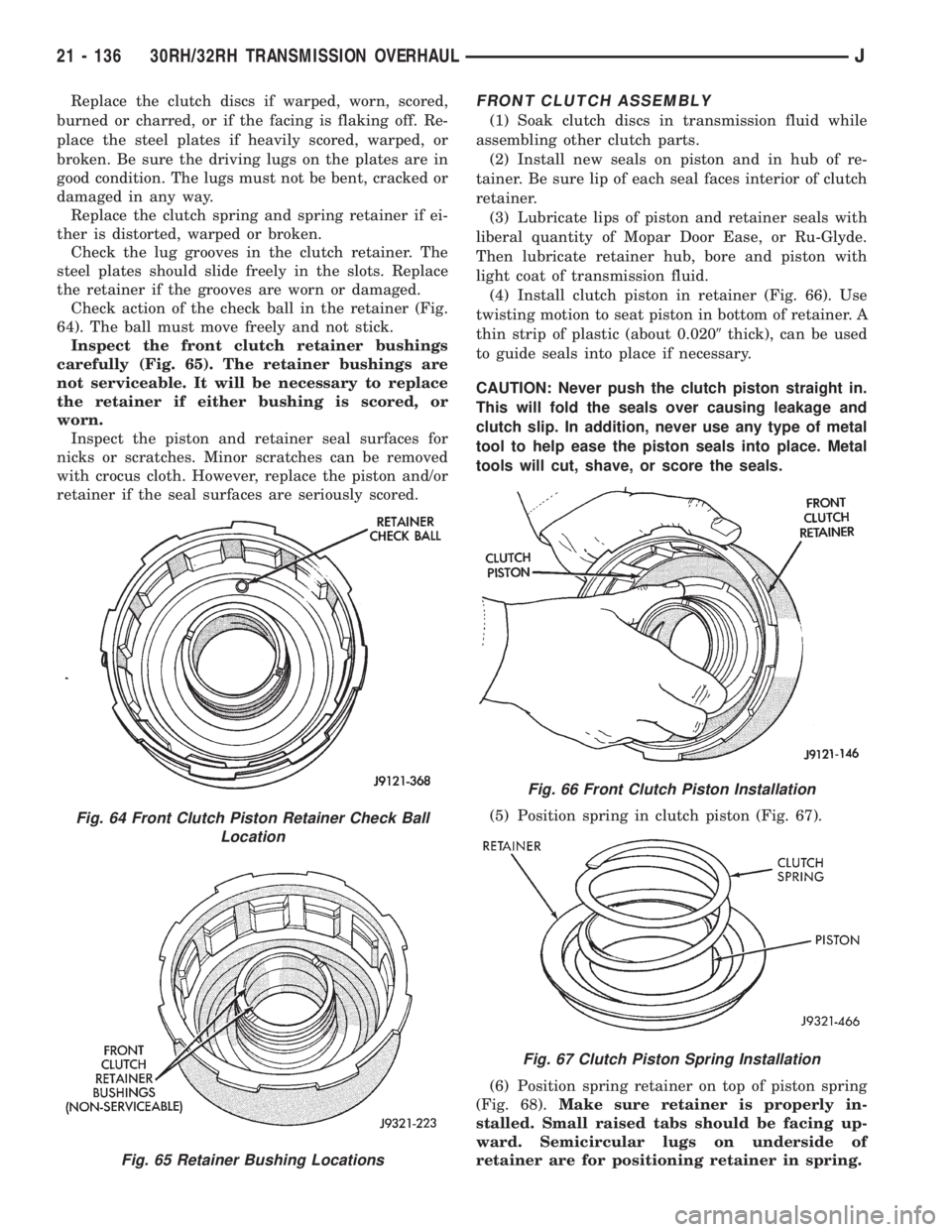
Check action of the check ball in the retainer (Fig.
64). The ball must move freely and not stick.
Inspect the front clutch retainer bushings
carefully (Fig. 65). The retainer bushings are
not serviceable. It will be necessary to replace
the retainer if either bushing is scored, or
worn.
Inspect the piston and retainer seal surfaces for
nicks or scratches. Minor scratches can be removed
with crocus cloth. However, replace the piston and/or
retainer if the seal surfaces are seriously scored.FRONT CLUTCH ASSEMBLY
(1) Soak clutch discs in transmission fluid while
assembling other clutch parts.
(2) Install new seals on piston and in hub of re-
tainer. Be sure lip of each seal faces interior of clutch
retainer.
(3) Lubricate lips of piston and retainer seals with
liberal quantity of Mopar Door Ease, or Ru-Glyde.
Then lubricate retainer hub, bore and piston with
light coat of transmission fluid.
(4) Install clutch piston in retainer (Fig. 66). Use
twisting motion to seat piston in bottom of retainer. A
thin strip of plastic (about 0.0209thick), can be used
to guide seals into place if necessary.
CAUTION: Never push the clutch piston straight in.
This will fold the seals over causing leakage and
clutch slip. In addition, never use any type of metal
tool to help ease the piston seals into place. Metal
tools will cut, shave, or score the seals.
(5) Position spring in clutch piston (Fig. 67).
(6) Position spring retainer on top of piston spring
(Fig. 68).Make sure retainer is properly in-
stalled. Small raised tabs should be facing up-
ward. Semicircular lugs on underside of
retainer are for positioning retainer in spring.
Fig. 64 Front Clutch Piston Retainer Check Ball
Location
Fig. 65 Retainer Bushing Locations
Fig. 66 Front Clutch Piston Installation
Fig. 67 Clutch Piston Spring Installation
21 - 136 30RH/32RH TRANSMISSION OVERHAULJ
Page 1704 of 2158
planetary. All the washers have four locating tabs on
them. These tabs fit in the holes or slots provided in
each planetary gear.
Inspect the output shaft carefully. Pay particular
attention to the machined bushing/bearing surfaces
on the shaft and the governor valve shaft bore at the
shaft rear.
Replace the output shaft if the machined surfaces
are scored, pitted, or damaged in any way. Also re-
place the shaft if the splines are damaged, or exhib-
it cracks at any location (especially at the governor
valve shaft bore).
The annulus gears can be removed from their sup-
ports if necessary. Just remove the snap rings and sep-
arate the two parts when replacement is necessary. In
addition, the annulus gear bushings can be replaced if
severely worn, or scored. However it is not necessary to
replace the bushings if they only exhibit normal wear.
Check bushing fit on the output shaft to be sure.
ASSEMBLING PLANETARY GEARTRAIN
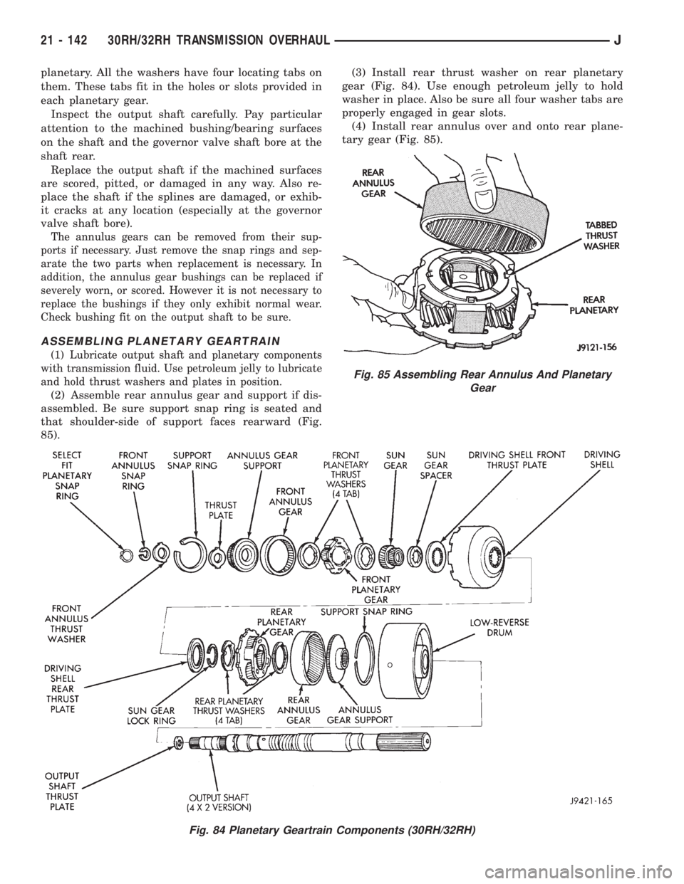
(1) Lubricate output shaft and planetary components
with transmission fluid. Use petroleum jelly to lubricate
and hold thrust washers and plates in position.
(2) Assemble rear annulus gear and support if dis-
assembled. Be sure support snap ring is seated and
that shoulder-side of support faces rearward (Fig.
85).(3) Install rear thrust washer on rear planetary
gear (Fig. 84). Use enough petroleum jelly to hold
washer in place. Also be sure all four washer tabs are
properly engaged in gear slots.
(4) Install rear annulus over and onto rear plane-
tary gear (Fig. 85).
Fig. 84 Planetary Geartrain Components (30RH/32RH)
Fig. 85 Assembling Rear Annulus And Planetary
Gear
21 - 142 30RH/32RH TRANSMISSION OVERHAULJ
Page 1705 of 2158
(5) Install assembled rear planetary and annulus
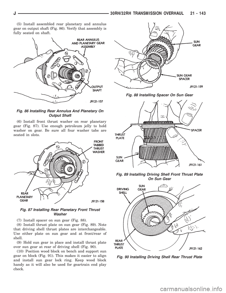
gear on output shaft (Fig. 86). Verify that assembly is
fully seated on shaft.
(6) Install front thrust washer on rear planetary
gear (Fig. 87). Use enough petroleum jelly to hold
washer on gear. Be sure all four washer tabs are
seated in slots.
(7) Install spacer on sun gear (Fig. 88).
(8) Install thrust plate on sun gear (Fig. 89). Note
that driving shell thrust plates are interchangeable.
Use either plate on sun gear and at front/rear of
shell.
(9) Hold sun gear in place and install thrust plate
over sun gear at rear of driving shell (Fig. 90).
(10) Position wood block on bench and support sun
gear on block (Fig. 91). This makes it easier to align
and install sun gear lock ring. Keep wood block
handy as it will also be used for geartrain end play
check.
Fig. 86 Installing Rear Annulus And Planetary On
Output Shaft
Fig. 87 Installing Rear Planetary Front Thrust
Washer
Fig. 88 Installing Spacer On Sun Gear
Fig. 89 Installing Driving Shell Front Thrust Plate
On Sun Gear
Fig. 90 Installing Driving Shell Rear Thrust Plate
J30RH/32RH TRANSMISSION OVERHAUL 21 - 143
Page 1706 of 2158
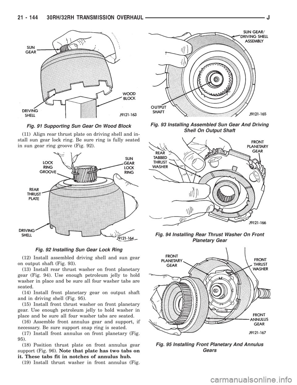
(11) Align rear thrust plate on driving shell and in-
stall sun gear lock ring. Be sure ring is fully seated
in sun gear ring groove (Fig. 92).
(12) Install assembled driving shell and sun gear
on output shaft (Fig. 93).
(13) Install rear thrust washer on front planetary
gear (Fig. 94). Use enough petroleum jelly to hold
washer in place and be sure all four washer tabs are
seated.
(14) Install front planetary gear on output shaft
and in driving shell (Fig. 95).
(15) Install front thrust washer on front planetary
gear. Use enough petroleum jelly to hold washer in
place and be sure all four washer tabs are seated.
(16) Assemble front annulus gear and support, if
necessary. Be sure support snap ring is seated.
(17) Install front annulus on front planetary (Fig.
95).
(18) Position thrust plate on front annulus gear
support (Fig. 96).Note that plate has two tabs on
it. These tabs fit in notches of annulus hub.
(19) Install thrust washer in front annulus (Fig.
Fig. 91 Supporting Sun Gear On Wood Block
Fig. 92 Installing Sun Gear Lock Ring
Fig. 93 Installing Assembled Sun Gear And Driving
Shell On Output Shaft
Fig. 94 Installing Rear Thrust Washer On Front
Planetary Gear
Fig. 95 Installing Front Planetary And Annulus
Gears
21 - 144 30RH/32RH TRANSMISSION OVERHAULJ
Page 1745 of 2158
(6) Let engine run at normal curb idle speed, apply
service brakes. Then shift transmission through all
gear ranges and back to PARK (leave engine run-
ning).
(7) Remove dipstick and check fluid level. Add only
enough fluid to bring level to Full mark on dipstick.
Do not overfill.If too much fluid is added, excess
amount can be removed with suction gun and
plastic tubing. Tubing only has to be long
enough to extend into oil pan.
(8) When fluid level is correct, shut engine off, re-
lease park brake, remove funnel, and reseat dipstick
in fill tube.
TRANSMISSION CONTROL MODULE (TCM)
SERVICE
Use the DRB scan tool to diagnose transmission
control module function whenever a fault is sus-
pected. Replace the module only when the scan tool
indicates the module is actually faulty.
TRANSMISSION CONTROL MODULE
REPLACEMENT
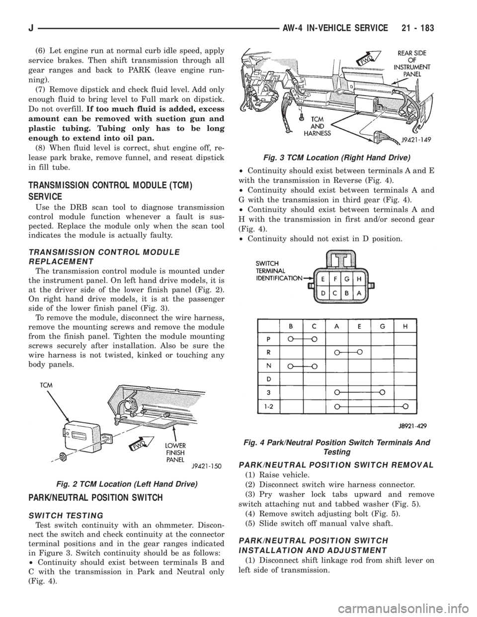
The transmission control module is mounted under
the instrument panel. On left hand drive models, it is
at the driver side of the lower finish panel (Fig. 2).
On right hand drive models, it is at the passenger
side of the lower finish panel (Fig. 3).
To remove the module, disconnect the wire harness,
remove the mounting screws and remove the module
from the finish panel. Tighten the module mounting
screws securely after installation. Also be sure the
wire harness is not twisted, kinked or touching any
body panels.
PARK/NEUTRAL POSITION SWITCH
SWITCH TESTING
Test switch continuity with an ohmmeter. Discon-
nect the switch and check continuity at the connector
terminal positions and in the gear ranges indicated
in Figure 3. Switch continuity should be as follows:
²Continuity should exist between terminals B and
C with the transmission in Park and Neutral only
(Fig. 4).²Continuity should exist between terminals A and E
with the transmission in Reverse (Fig. 4).
²Continuity should exist between terminals A and
G with the transmission in third gear (Fig. 4).
²Continuity should exist between terminals A and
H with the transmission in first and/or second gear
(Fig. 4).
²Continuity should not exist in D position.
PARK/NEUTRAL POSITION SWITCH REMOVAL
(1) Raise vehicle.
(2) Disconnect switch wire harness connector.
(3) Pry washer lock tabs upward and remove
switch attaching nut and tabbed washer (Fig. 5).
(4) Remove switch adjusting bolt (Fig. 5).
(5) Slide switch off manual valve shaft.
PARK/NEUTRAL POSITION SWITCH
INSTALLATION AND ADJUSTMENT
(1) Disconnect shift linkage rod from shift lever on
left side of transmission.
Fig. 2 TCM Location (Left Hand Drive)
Fig. 3 TCM Location (Right Hand Drive)
Fig. 4 Park/Neutral Position Switch Terminals And
Testing
JAW-4 IN-VEHICLE SERVICE 21 - 183