Page 1746 of 2158

(2) Rotate manual shift lever all the way rearward.
Then rotate lever forward two detent positions to
Neutral.
(3) Install switch on manual valve shaft and in-
stall switch adjusting bolt finger tight. Do not tighten
bolt at this time.
(4) Install tabbed washer on manual valve shaft
and install switch attaching nut. Tighten nut to 6.9
Nzm (61 in. lbs.) torque but do not bend washer lock
tabs over nut at this time.
(5) Verify that transmission is in Neutral.
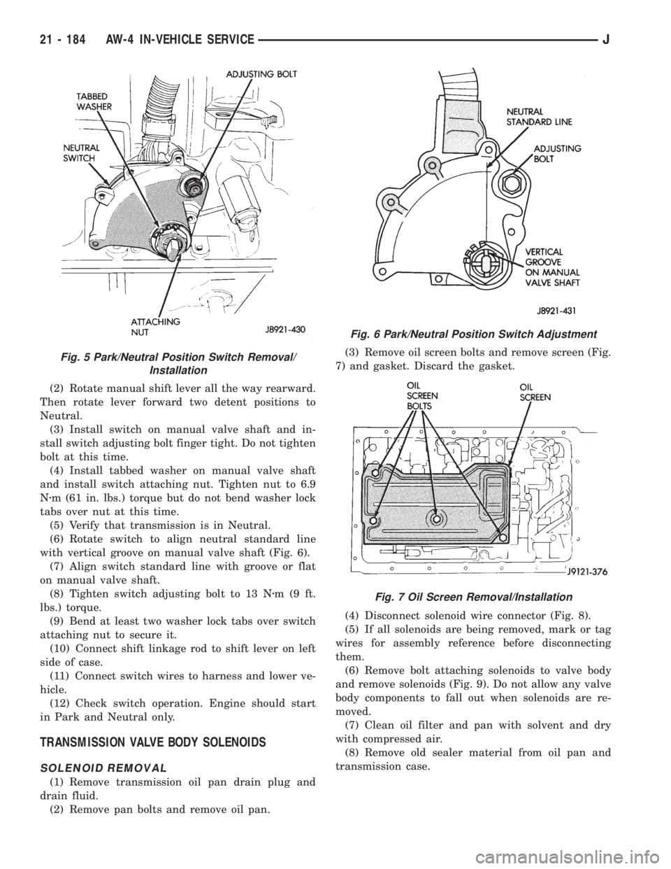
(6) Rotate switch to align neutral standard line
with vertical groove on manual valve shaft (Fig. 6).
(7) Align switch standard line with groove or flat
on manual valve shaft.
(8) Tighten switch adjusting bolt to 13 Nzm(9ft.
lbs.) torque.
(9) Bend at least two washer lock tabs over switch
attaching nut to secure it.
(10) Connect shift linkage rod to shift lever on left
side of case.
(11) Connect switch wires to harness and lower ve-
hicle.
(12) Check switch operation. Engine should start
in Park and Neutral only.
TRANSMISSION VALVE BODY SOLENOIDS
SOLENOID REMOVAL
(1) Remove transmission oil pan drain plug and
drain fluid.
(2) Remove pan bolts and remove oil pan.(3) Remove oil screen bolts and remove screen (Fig.
7) and gasket. Discard the gasket.
(4) Disconnect solenoid wire connector (Fig. 8).
(5) If all solenoids are being removed, mark or tag
wires for assembly reference before disconnecting
them.
(6) Remove bolt attaching solenoids to valve body
and remove solenoids (Fig. 9). Do not allow any valve
body components to fall out when solenoids are re-
moved.
(7) Clean oil filter and pan with solvent and dry
with compressed air.
(8) Remove old sealer material from oil pan and
transmission case.
Fig. 5 Park/Neutral Position Switch Removal/
Installation
Fig. 6 Park/Neutral Position Switch Adjustment
Fig. 7 Oil Screen Removal/Installation
21 - 184 AW-4 IN-VEHICLE SERVICEJ
Page 1760 of 2158

AW-4 TRANSMISSION REMOVAL AND INSTALLATION
INDEX
page page
Oil Pump Seal Replacement................ 199
Torque Converter Stator Clutch Inspection...... 199Transmission and Torque Converter Installation . . 199
Transmission and Torque Converter Removal.... 198
TRANSMISSION AND TORQUE CONVERTER
REMOVAL
(1) Raise vehicle.
(2) Drain transmission fluid and reinstall oil pan
drain plug.
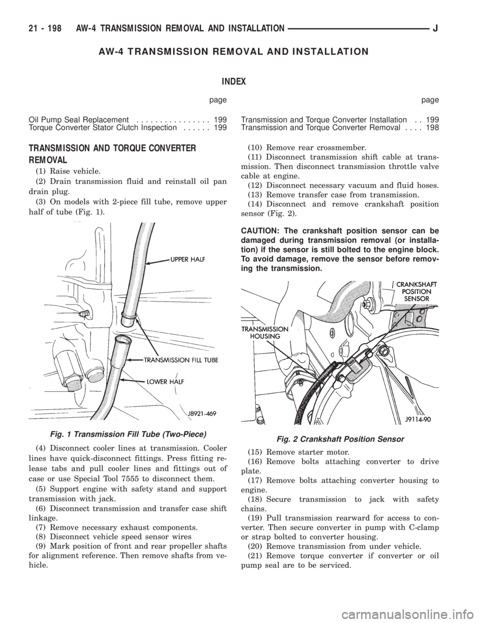
(3) On models with 2-piece fill tube, remove upper
half of tube (Fig. 1).
(4) Disconnect cooler lines at transmission. Cooler
lines have quick-disconnect fittings. Press fitting re-
lease tabs and pull cooler lines and fittings out of
case or use Special Tool 7555 to disconnect them.
(5) Support engine with safety stand and support
transmission with jack.
(6) Disconnect transmission and transfer case shift
linkage.
(7) Remove necessary exhaust components.
(8) Disconnect vehicle speed sensor wires
(9) Mark position of front and rear propeller shafts
for alignment reference. Then remove shafts from ve-
hicle.(10) Remove rear crossmember.
(11) Disconnect transmission shift cable at trans-
mission. Then disconnect transmission throttle valve
cable at engine.
(12) Disconnect necessary vacuum and fluid hoses.
(13) Remove transfer case from transmission.
(14) Disconnect and remove crankshaft position
sensor (Fig. 2).
CAUTION: The crankshaft position sensor can be
damaged during transmission removal (or installa-
tion) if the sensor is still bolted to the engine block.
To avoid damage, remove the sensor before remov-
ing the transmission.
(15) Remove starter motor.
(16) Remove bolts attaching converter to drive
plate.
(17) Remove bolts attaching converter housing to
engine.
(18) Secure transmission to jack with safety
chains.
(19) Pull transmission rearward for access to con-
verter. Then secure converter in pump with C-clamp
or strap bolted to converter housing.
(20) Remove transmission from under vehicle.
(21) Remove torque converter if converter or oil
pump seal are to be serviced.
Fig. 1 Transmission Fill Tube (Two-Piece)Fig. 2 Crankshaft Position Sensor
21 - 198 AW-4 TRANSMISSION REMOVAL AND INSTALLATIONJ
Page 1802 of 2158

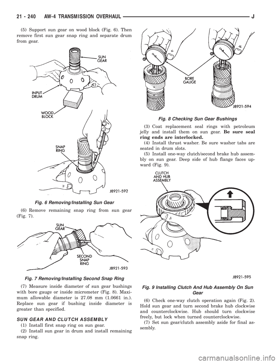
(5) Support sun gear on wood block (Fig. 6). Then
remove first sun gear snap ring and separate drum
from gear.
(6) Remove remaining snap ring from sun gear
(Fig. 7).
(7) Measure inside diameter of sun gear bushings
with bore gauge or inside micrometer (Fig. 8). Maxi-
mum allowable diameter is 27.08 mm (1.0661 in.).
Replace sun gear if bushing inside diameter is
greater than specified.
SUN GEAR AND CLUTCH ASSEMBLY
(1) Install first snap ring on sun gear.
(2) Install sun gear in drum and install remaining
snap ring.(3) Coat replacement seal rings with petroleum
jelly and install them on sun gear.Be sure seal
ring ends are interlocked.
(4) Install thrust washer. Be sure washer tabs are
seated in drum slots.
(5) Install one-way clutch/second brake hub assem-
bly on sun gear. Deep side of hub flange faces up-
ward (Fig. 9).
(6) Check one-way clutch operation again (Fig. 2).
Hold sun gear and turn second brake hub clockwise
and counterclockwise. Hub should turn clockwise
freely, but lock when turned counterclockwise.
(7) Set sun gear/clutch assembly aside for final as-
sembly.
Fig. 6 Removing/Installing Sun Gear
Fig. 7 Removing/Installing Second Snap Ring
Fig. 8 Checking Sun Gear Bushings
Fig. 9 Installing Clutch And Hub Assembly On Sun
Gear
21 - 240 AW-4 TRANSMISSION OVERHAULJ
Page 1805 of 2158
SECOND BRAKE ASSEMBLY
(1) Lubricate and install new O-rings on brake pis-
ton. Then install brake piston in drum.
(2) Install return springs and retainer on brake
piston.
(3) Compress return springs with shop press and
Compressor Tool 7538. Install piston snap ring and
remove brake assembly from press.
(4) Check brake piston operation with low pressure
compressed air (Fig. 7). Apply air pressure through
feed hole in drum. Piston should move smoothly
when applying-releasing air pressure.(5) Coat thrust washer with petroleum jelly and
install it in drum. Be sure washer notches are
aligned with tabs on spring retainer (Fig. 8).
(6) Set brake components aside for final assembly.
Fig. 7 Checking Second Brake Piston Operation
Fig. 8 Installing Second Brake Thrust Washer
JAW-4 TRANSMISSION OVERHAUL 21 - 243
Page 1831 of 2158
(21) Check brake pack clearance with feeler gauge
(Fig. 16). Clearance should be 0.062 - 1.98 mm (0.024
- 0.078 in.). If brake pack clearance is not correct,
brake pack components are not seated. Reassemble
brake pack if necessary.
(22) Install planetary sun gear and input drum
(Fig. 17). Be sure drum thrust washer tabs are
seated in drum. Use petroleum jelly to hold thrust
washer in position if necessary.(23) Install front planetary gear on sun gear (Fig.
18).
(24) Support output shaft with wood blocks (Fig.
19).
Fig. 16 Checking Second Brake Pack Clearance
Fig. 17 Installing Sun Gear And Input Drum
Fig. 18 Installing Front Planetary Gear
Fig. 19 Supporting Output Shaft
JAW-4 TRANSMISSION OVERHAUL 21 - 269
Page 1832 of 2158
(25) Install planetary snap ring on sun gear with
snap ring plier tool 7541 (Fig. 20).
(26) Install tabbed thrust race on front planetary
gear (Fig. 21). Washer tabs face down and toward
gear. Race outer diameter is 47.8 mm (1.882 in.). In-
side diameter is 34.3 mm (1.350 in.).
(27) Install second coast brake band (Fig. 22).
(28) Install pin in second coast brake band. Then
install retaining ring on pin (Fig. 23).
(29) Install thrust bearing and race in forward-di-
rect clutch (Fig. 24). Coat bearing/race with petro-
leum jelly to hold them in place.
Fig. 22 Installing Second Coast Brake Band
Fig. 23 Installing Second Coast Brake Band Retaining Pin
Fig. 20 Installing Front Planetary Snap Ring
Fig. 21 Installing Planetary Thrust Race
21 - 270 AW-4 TRANSMISSION OVERHAULJ
Page 1843 of 2158
(94) Mount park/neutral position switch on manual
valve shaft and tighten switch adjusting bolt just
enough to keep switch from moving (Fig. 68).
(95) Install park/neutral position switch tabbed
washer and retaining nut (Fig. 68). Tighten nut to
6.9 Nzm (61 in. lbs.) torque, but do not bend any of
the washer tabs against the nut at this time.
(96) Align park/neutral position switch standard
line with groove or flat on manual shaft (Fig. 68).(97) Tighten park/neutral position switch adjusting
bolt to 13 Nzm (9 ft. lbs.) torque.
(98) Install transmission shift lever on manual
valve shaft. Tighten lever attaching nut to 16 Nzm
(12 ft. lbs.) torque.
Fig. 65 Applying Sealer To Case Rear Flange
Fig. 66 Installing Transmission Speed Sensor
Fig. 67 Installing Converter Housing
Fig. 68 Park/Neutral Position Switch Installation/
Adjustment
JAW-4 TRANSMISSION OVERHAUL 21 - 281
Page 2084 of 2158

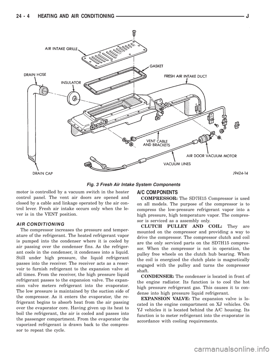
motor is controlled by a vacuum switch in the heater
control panel. The vent air doors are opened and
closed by a cable and linkage operated by the air con-
trol lever. Fresh air intake occurs only when the le-
ver is in the VENT position.
AIR CONDITIONING
The compressor increases the pressure and temper-
ature of the refrigerant. The heated refrigerant vapor
is pumped into the condenser where it is cooled by
air passing over the condenser fins. As the refriger-
ant cools in the condenser, it condenses into a liquid.
Still under high pressure, the liquid refrigerant
passes into the receiver. The receiver acts as a reser-
voir to furnish refrigerant to the expansion valve at
all times. From the receiver, the high pressure liquid
refrigerant passes to the expansion valve. The expan-
sion valve meters refrigerant into the evaporator.
The low pressure is maintained by the suction side of
the compressor. As it enters the evaporator, the re-
frigerant begins to absorb heat from the air passing
over the evaporator core. Having given up its heat to
boil the refrigerant, the air is cooled and passes into
the passenger compartment. From the evaporator the
vaporized refrigerant is drawn back to the compres-
sor to repeat the cycle.
A/C COMPONENTS
COMPRESSOR:The SD7H15 Compressor is used
on all models. The purpose of the compressor is to
compress the low-pressure refrigerant vapor into a
high pressure, high temperature vapor. The compres-
sor is serviced as a assembly only.
CLUTCH PULLEY AND COIL:They are
mounted on the compressor and providing a way to
drive the compressor. The compressor clutch and coil
are the only serviced parts on the SD7H15 compres-
sor. When the compressor is not in operation, the
pulley free wheels on the clutch hub bearing. When
the coil is energized the clutch plate is magnetically
engaged with the pulley and turns the compressor
shaft.
CONDENSER:The condenser is located in front of
the engine radiator. Its function is to cool the hot
high pressure refrigerant gas. This causes it to con-
dense into high pressure liquid refrigerant.
EXPANSION VALVE:The expansion valve is lo-
cated in the engine compartment on XJ vehicles. On
YJ vehicles it is located behind the A/C housing. Its
function is to meter refrigerant into the evaporator in
accordance with cooling requirements.
Fig. 3 Fresh Air Intake System Components
24 - 4 HEATING AND AIR CONDITIONINGJ