Page 1844 of 2158
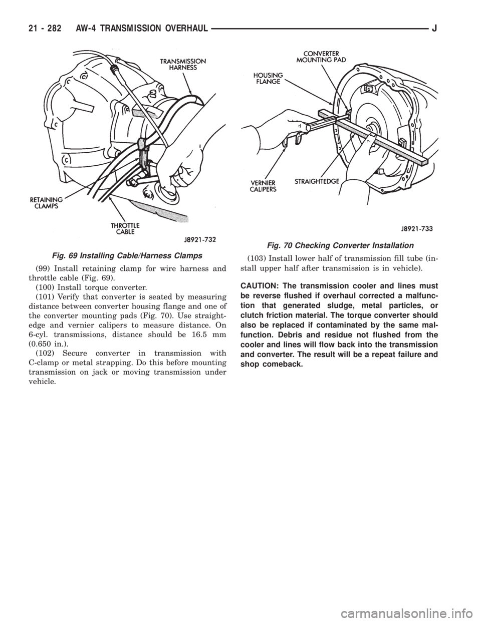
(99) Install retaining clamp for wire harness and
throttle cable (Fig. 69).
(100) Install torque converter.
(101) Verify that converter is seated by measuring
distance between converter housing flange and one of
the converter mounting pads (Fig. 70). Use straight-
edge and vernier calipers to measure distance. On
6-cyl. transmissions, distance should be 16.5 mm
(0.650 in.).
(102) Secure converter in transmission with
C-clamp or metal strapping. Do this before mounting
transmission on jack or moving transmission under
vehicle.(103) Install lower half of transmission fill tube (in-
stall upper half after transmission is in vehicle).
CAUTION: The transmission cooler and lines must
be reverse flushed if overhaul corrected a malfunc-
tion that generated sludge, metal particles, or
clutch friction material. The torque converter should
also be replaced if contaminated by the same mal-
function. Debris and residue not flushed from the
cooler and lines will flow back into the transmission
and converter. The result will be a repeat failure and
shop comeback.
Fig. 69 Installing Cable/Harness Clamps
Fig. 70 Checking Converter Installation
21 - 282 AW-4 TRANSMISSION OVERHAULJ
Page 1849 of 2158
(4) Lower vehicle.
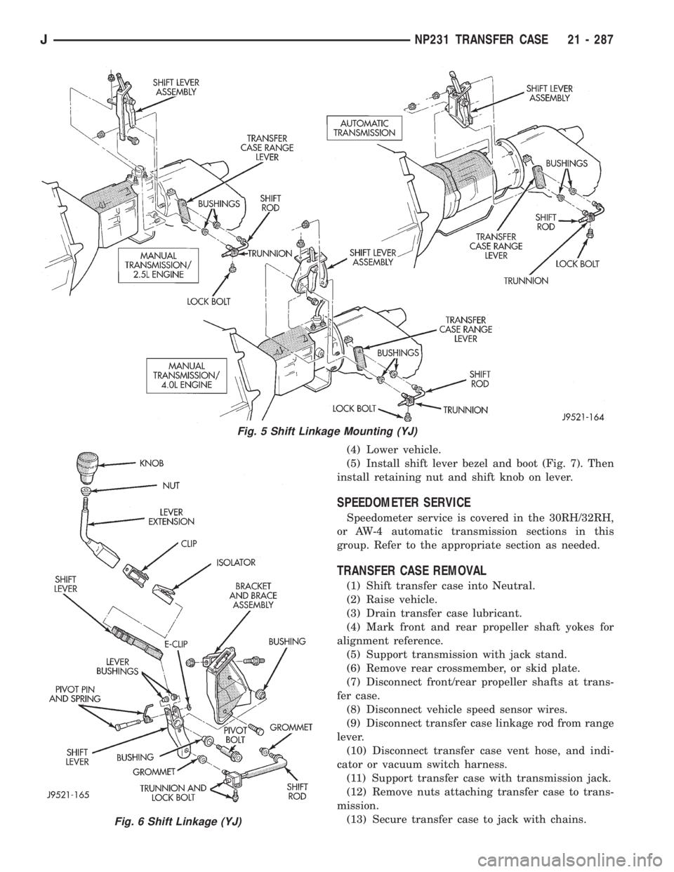
(5) Install shift lever bezel and boot (Fig. 7). Then
install retaining nut and shift knob on lever.
SPEEDOMETER SERVICE
Speedometer service is covered in the 30RH/32RH,
or AW-4 automatic transmission sections in this
group. Refer to the appropriate section as needed.
TRANSFER CASE REMOVAL
(1) Shift transfer case into Neutral.
(2) Raise vehicle.
(3) Drain transfer case lubricant.
(4) Mark front and rear propeller shaft yokes for
alignment reference.
(5) Support transmission with jack stand.
(6) Remove rear crossmember, or skid plate.
(7) Disconnect front/rear propeller shafts at trans-
fer case.
(8) Disconnect vehicle speed sensor wires.
(9) Disconnect transfer case linkage rod from range
lever.
(10) Disconnect transfer case vent hose, and indi-
cator or vacuum switch harness.
(11) Support transfer case with transmission jack.
(12) Remove nuts attaching transfer case to trans-
mission.
(13) Secure transfer case to jack with chains.
Fig. 5 Shift Linkage Mounting (YJ)
Fig. 6 Shift Linkage (YJ)
JNP231 TRANSFER CASE 21 - 287
Page 1850 of 2158
(14) Pull transfer case and jack rearward to disen-
gage transfer case.
(15) Remove transfer case from under vehicle.
(16) If transfer case was removed for overhaul, re-
move damper from rear retainer.
TRANSFER CASE INSTALLATION
(1) Mount transfer case on a transmission jack. Se-
cure transfer case to jack with chains.
(2) Position transfer case under vehicle.(3) Align transfer case and transmission shafts and
install transfer case on transmission.
(4) Install and tighten transfer case attaching nuts
to 35 Nzm (26 ft. lbs.) torque.
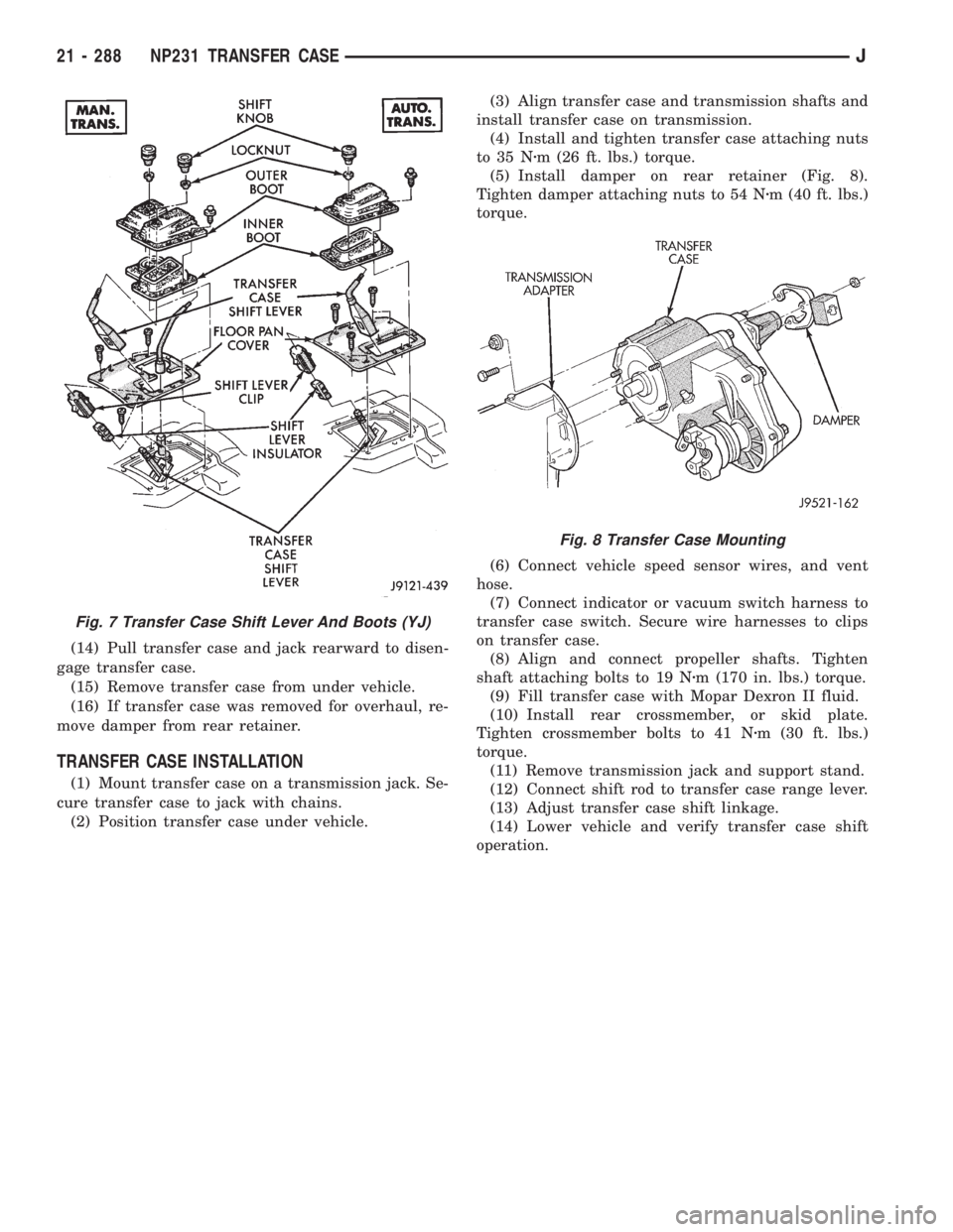
(5) Install damper on rear retainer (Fig. 8).
Tighten damper attaching nuts to 54 Nzm (40 ft. lbs.)
torque.
(6) Connect vehicle speed sensor wires, and vent
hose.
(7) Connect indicator or vacuum switch harness to
transfer case switch. Secure wire harnesses to clips
on transfer case.
(8) Align and connect propeller shafts. Tighten
shaft attaching bolts to 19 Nzm (170 in. lbs.) torque.
(9) Fill transfer case with Mopar Dexron II fluid.
(10) Install rear crossmember, or skid plate.
Tighten crossmember bolts to 41 Nzm (30 ft. lbs.)
torque.
(11) Remove transmission jack and support stand.
(12) Connect shift rod to transfer case range lever.
(13) Adjust transfer case shift linkage.
(14) Lower vehicle and verify transfer case shift
operation.
Fig. 7 Transfer Case Shift Lever And Boots (YJ)
Fig. 8 Transfer Case Mounting
21 - 288 NP231 TRANSFER CASEJ
Page 1857 of 2158
FRONT CASE ASSEMBLY
(1) Lubricate components with automatic transmis-
sion fluid (or petroleum jelly where indicated) during
assembly.
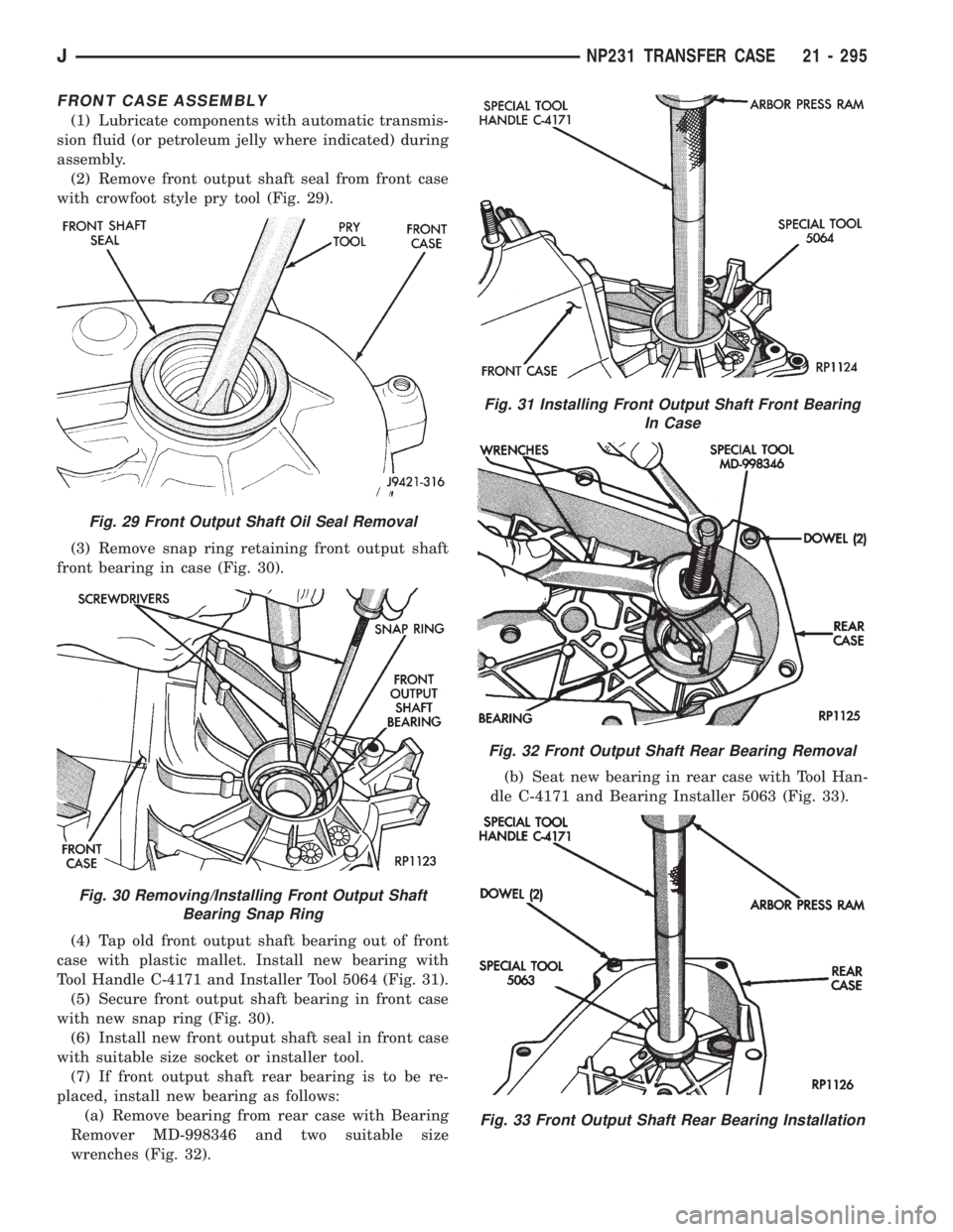
(2) Remove front output shaft seal from front case
with crowfoot style pry tool (Fig. 29).
(3) Remove snap ring retaining front output shaft
front bearing in case (Fig. 30).
(4) Tap old front output shaft bearing out of front
case with plastic mallet. Install new bearing with
Tool Handle C-4171 and Installer Tool 5064 (Fig. 31).
(5) Secure front output shaft bearing in front case
with new snap ring (Fig. 30).
(6) Install new front output shaft seal in front case
with suitable size socket or installer tool.
(7) If front output shaft rear bearing is to be re-
placed, install new bearing as follows:
(a) Remove bearing from rear case with Bearing
Remover MD-998346 and two suitable size
wrenches (Fig. 32).(b) Seat new bearing in rear case with Tool Han-
dle C-4171 and Bearing Installer 5063 (Fig. 33).
Fig. 29 Front Output Shaft Oil Seal Removal
Fig. 30 Removing/Installing Front Output Shaft
Bearing Snap Ring
Fig. 31 Installing Front Output Shaft Front Bearing
In Case
Fig. 32 Front Output Shaft Rear Bearing Removal
Fig. 33 Front Output Shaft Rear Bearing Installation
JNP231 TRANSFER CASE 21 - 295
Page 1861 of 2158
(2) Install shift sector in the case (Fig. 48).
(3) Install range lever and lever attaching nut on
shift sector. Tighten attaching nut to 30 Nzm (22 ft.
lbs.) torque.
(4) Install detent plunger, spring and plug (Fig.
49). Tighten plug to 20 Nzm (15 ft. lbs.) torque.
(5) Inspect pads on range fork (Fig. 50). Be sure
pads are secure and in position. Replace fork as an
assembly if pads are worn through, or broken.
(6) Assemble range fork and shift hub (Fig. 51).
(7) Engage range fork pin in shift sector slot (Fig.
52).
(8) Insert shift hub in low range gear. Be sure hub
is fully seated.
Fig. 48 Shift Sector Installation
Fig. 49 Installing Detent Plunger, Spring And Plug
Fig. 50 Range Fork Pad Locations
Fig. 51 Assembling Range Fork And Shift Hub
Fig. 52 Seating Range Fork Pin In Shift Sector Slot
JNP231 TRANSFER CASE 21 - 299
Page 1866 of 2158
(19) Apply 3 mm (1/8 in.) wide bead of Mopar gas-
ket maker, silicone adhesive sealer, or Loctite 518 to
mounting surface of extension housing.(20) Align and install extension on retainer. Then
install and tighten extension bolts to 27-34 Nzm
(20-25 ft. lbs.) torque.
(21) Install new seal on front output shaft (Fig.
72).
(22) Install front yoke on front shaft. Secure yoke
with replacement nut. Tighten nut to 149 Nzm(110
ft. lbs.) torque.
(23) Install replacement gasket on indicator switch
and install switch in case.
(24) Install tighten drain plug to 47 Nzm (35 ft.
lbs.) torque.
(25) Install indicator or vacuum switch in case.
Tighten switch to 27-34 Nzm (20-25 ft. lbs.) torque.
(26) Install speedometer pinion and adapter.
(27) Fill transfer case with recommended lubri-
cant.
(28) Install and tighten fill plug to 41 Nzm (35 ft.
lbs.) torque.
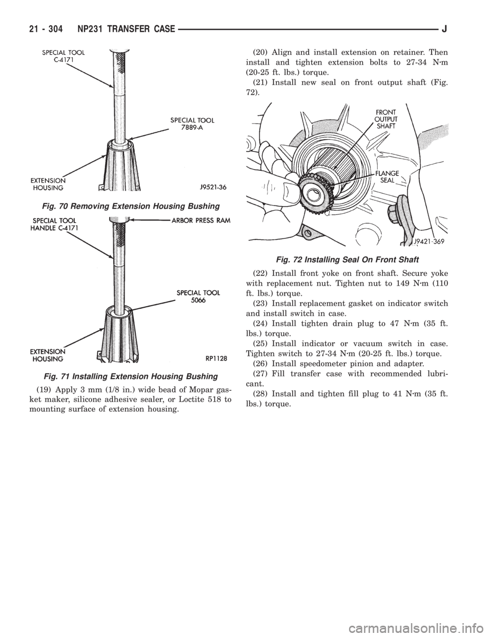
Fig. 70 Removing Extension Housing Bushing
Fig. 71 Installing Extension Housing Bushing
Fig. 72 Installing Seal On Front Shaft
21 - 304 NP231 TRANSFER CASEJ
Page 1871 of 2158
SHIFT LINKAGE ADJUSTMENT
(1) Shift transfer case into 4L position.
(2) Raise vehicle.
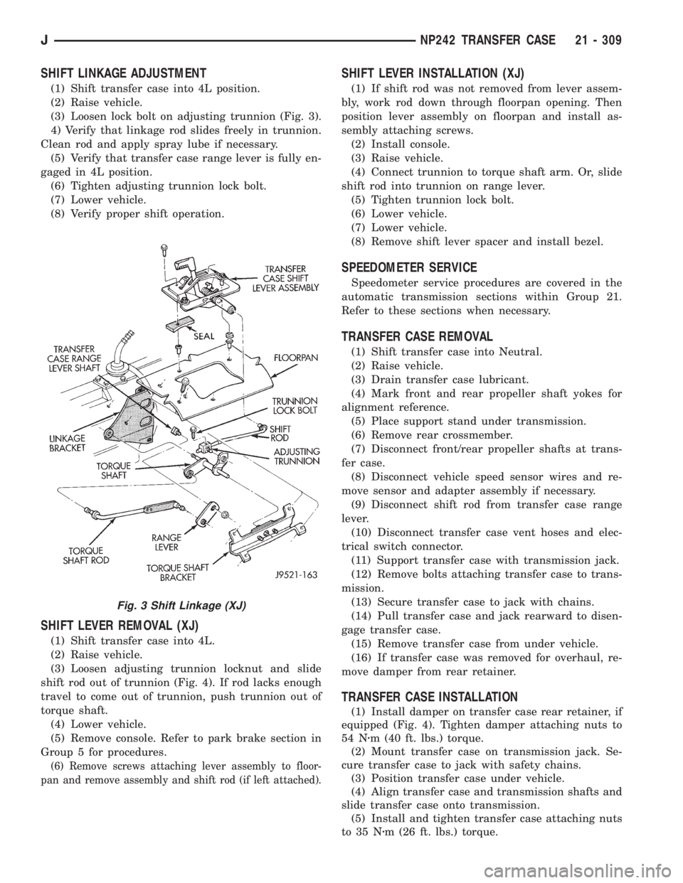
(3) Loosen lock bolt on adjusting trunnion (Fig. 3).
4) Verify that linkage rod slides freely in trunnion.
Clean rod and apply spray lube if necessary.
(5) Verify that transfer case range lever is fully en-
gaged in 4L position.
(6) Tighten adjusting trunnion lock bolt.
(7) Lower vehicle.
(8) Verify proper shift operation.
SHIFT LEVER REMOVAL (XJ)
(1) Shift transfer case into 4L.
(2) Raise vehicle.
(3) Loosen adjusting trunnion locknut and slide
shift rod out of trunnion (Fig. 4). If rod lacks enough
travel to come out of trunnion, push trunnion out of
torque shaft.
(4) Lower vehicle.
(5) Remove console. Refer to park brake section in
Group 5 for procedures.
(6) Remove screws attaching lever assembly to floor-
pan and remove assembly and shift rod (if left attached).
SHIFT LEVER INSTALLATION (XJ)
(1) If shift rod was not removed from lever assem-
bly, work rod down through floorpan opening. Then
position lever assembly on floorpan and install as-
sembly attaching screws.
(2) Install console.
(3) Raise vehicle.
(4) Connect trunnion to torque shaft arm. Or, slide
shift rod into trunnion on range lever.
(5) Tighten trunnion lock bolt.
(6) Lower vehicle.
(7) Lower vehicle.
(8) Remove shift lever spacer and install bezel.
SPEEDOMETER SERVICE
Speedometer service procedures are covered in the
automatic transmission sections within Group 21.
Refer to these sections when necessary.
TRANSFER CASE REMOVAL
(1) Shift transfer case into Neutral.
(2) Raise vehicle.
(3) Drain transfer case lubricant.
(4) Mark front and rear propeller shaft yokes for
alignment reference.
(5) Place support stand under transmission.
(6) Remove rear crossmember.
(7) Disconnect front/rear propeller shafts at trans-
fer case.
(8) Disconnect vehicle speed sensor wires and re-
move sensor and adapter assembly if necessary.
(9) Disconnect shift rod from transfer case range
lever.
(10) Disconnect transfer case vent hoses and elec-
trical switch connector.
(11) Support transfer case with transmission jack.
(12) Remove bolts attaching transfer case to trans-
mission.
(13) Secure transfer case to jack with chains.
(14) Pull transfer case and jack rearward to disen-
gage transfer case.
(15) Remove transfer case from under vehicle.
(16) If transfer case was removed for overhaul, re-
move damper from rear retainer.
TRANSFER CASE INSTALLATION
(1) Install damper on transfer case rear retainer, if
equipped (Fig. 4). Tighten damper attaching nuts to
54 Nzm (40 ft. lbs.) torque.
(2) Mount transfer case on transmission jack. Se-
cure transfer case to jack with safety chains.
(3) Position transfer case under vehicle.
(4) Align transfer case and transmission shafts and
slide transfer case onto transmission.
(5) Install and tighten transfer case attaching nuts
to 35 Nzm (26 ft. lbs.) torque.
Fig. 3 Shift Linkage (XJ)
JNP242 TRANSFER CASE 21 - 309
Page 1888 of 2158
(40) Install mode sleeve in mode fork (Fig. 63).
Then install assembled sleeve and fork on mainshaft.
Be sure mode sleeve splines are engaged in differen-
tial splines.
(41) Install mode fork and mainshaft assembly in
case (Fig. 64). Rotate mainshaft slightly to engage
shaft with low range gears.
(42) Rotate mode fork pin into shift sector slot.
(43) Install shift rail (Fig. 65).Be sure rail is
seated in both shift forks.
(44) Rotate shift sector to align lockpin hole in low
range fork with access hole in case.
(45) Insert an easy-out in range fork lockpin to
hold it securely for installation (Fig. 66).Lockpin is
slightly tapered on one end. Insert tapered end
into fork and rail.
Fig. 63 Installing Mode Fork And Sleeve
Fig. 64 Assembled Mainshaft And Mode Fork
Installation
Fig. 65 Shift Rail Installation
21 - 326 NP242 TRANSFER CASEJ