1995 JEEP YJ ECU
[x] Cancel search: ECUPage 1985 of 2158
INSTALLATION
(1) Apply adhesive to the act surface on the sup-
port bracket according as follows:
²crush the vial in the plastic housing of the accel-
erator to saturate the felt applicator.
²remove the paper sleeve.
²apply a generous amount of accelerator to the con-
tact surface on the mirror support bracket.
²do not touch the support bracket contact surface
after the accelerator has been applied.
²
allow the accelerator to dry for at least five minutes.
and
(2) Apply accelerator to the support bracket con-
tact surface on the windshield glass. Allow the accel-
erator to dry for one minute.
(3) Install the mirror bracket on the windshield
glass as follows:
²apply one drop of adhesive at the center of support
bracket contact surface on windshield glass.
²immediately apply an even coat of adhesive to the
contact surface on the support bracket.
²align the support bracket with the position refer-
ence lines on the windshield glass, then
²press and hold the support bracket in-place for at
least one minute.
Ensure that the mirror support bracket is
correctly aligned because the adhesive will
cure rapidly.
(4) Allow the adhesive to cure for 8-10 minutes,
then remove any residue adhesive with an alcohol-
dampened cloth.
(5) Allow the adhesive to cure for an additional
8-10 minutes before installing the mirror base on the
support bracket.
DESCRIPTION AND OPERATION
SAFETY PRECAUTIONS
WARNING: DO NOT OPERATE THE VEHICLE
WITHIN 24 HOURS OF WINDSHIELD INSTALLATION.
IT TAKES AT LEAST 24 HOURS FOR THE URE-
THANE ADHESIVE TO CURE. IF IT IS NOT CURED,
THE WINDSHIELD MAY NOT PERFORM PROPERLY
IN AN ACCIDENT.
URETHANE ADHESIVES ARE APPLIED AS A SYS-
TEM. USE GLASS CLEANER, GLASS PREP SOL-
VENT, GLASS PRIMER, AND PINCHWELD (FENCE)
PRIMER PROVIDED BY THE ADHESIVE MANUFAC-
TURER. IF NOT, STRUCTURAL INTEGRITY COULD
BE COMPROMISED.
BE SURE TO REFER TO THE URETHANE MANU-
FACTURER'S DIRECTIONS FOR CURING TIME
SPECIFICATIONS, AND DO NOT USE ADHESIVE AF-
TER ITS EXPIRATION DATE.
VAPORS THAT ARE EMITTED FROM THE URE-
THANE ADHESIVE OR PRIMER COULD CAUSE
PERSONAL INJURY, USE THEM IN A WELL VENTI-
LATED AREA.
SKIN CONTACT WITH URETHANE ADHESIVE
SHOULD BE AVOIDED, OR PERSONAL INJURY MAY
RESULT.
ALWAYS WEAR EYE AND HAND PROTECTION
WHEN WORKING WITH GLASS.
CAUTION: Protect all painted or trimmed surfaces
from coming in contact with urethane or primers.
Be careful not to damage painted surfaces when
removing moldings or cutting urethane around
windshield.
It is difficult to salvage a windshield during the re-
moval operation. The windshield is part of the struc-
tural support for the roof. The urethane bonding
used to secure the windshield to the fence is difficult
to cut or clean from any surface. If the moldings are
set in urethane, it would also be unlikely they could
be salvaged. Before removing the windshield, check
the availability of the windshield and moldings from
the parts supplier.
JSTATIONARY WINDOW GLASSÐXJ 23 - 671995 Jeep Cherokee/Wrangler
Publication No. 81-370-5146
TSB 26-05-95 July, 1995
Page 1987 of 2158
(5) Start the hot knife blade (special tool C-4386)
between the glass and the urethane. Next, cut the
adhesive as close to the glass edge as possible (Fig.
1). Allow as much adhesive to remain on the pinch-
weld flange as possible.For best cutting results,
clean the knife blade frequently with steel wool
while the blade is hot.
(6) Remove the windshield glass from the body
opening.
(7) After the hot knife blade has cooled, clean the
blade with solvent and a clean cloth.
INSTALLATIONÐSHORT METHOD
Normally, after a replacement windshield glass is
installed, the rearview mirror bracket also requires
installation.Do not install the bracket until after
the windshield glass installation is completed.
(1) Inspect the windshield opening pinchweld
flanges. Prime any bare spots with urethane primer.
Allow a minimum of 18 minutes for dry time.
(2) Inspect urethane bead for high spots. Level
bead by shaving off high spots with a razor knife.
(3) Clean the outer edge of windshield glass with
naphtha or an equivalent product.
(4) Prime outer perimeter of interior side of glass 16
mm (5/8 inch) from edge. Use a wipe-off type urethane
primer and wipe glass dry after primer application.
NOTE: The reveal molding has an adhesive applied
to the windshield contact surface to help secure the
molding to the windshield during the installation
procedure.
(5) Apply the molding to the windshield:
²With the molding at room temperature, press the
molding onto the windshield corners.
²From corner to corner, work the molding to the
center of each side. (Some stretching of the mold-
ing may be required during this procedure.)(6) Place the glass on the pinchweld flanges and
inspect for gaps in the urethane. Gaps in excess of 3
mm (1/8 inch) must be filled with urethane.
(7) Adjust windshield glass position until it is
aligned with the flanges and adhesive. Next, make
alignment marks on the glass and body.
(8) Remove the windshield glass and position it on
a flat surface.
CAUTION: Avoid spilling or dripping primer on
painted surfaces. Clean spills or drips immediately.
The primer will damage the paint if it remains on
the surface for any length of time.
(9) If the replacement windshield glass does not
have blackout primer:
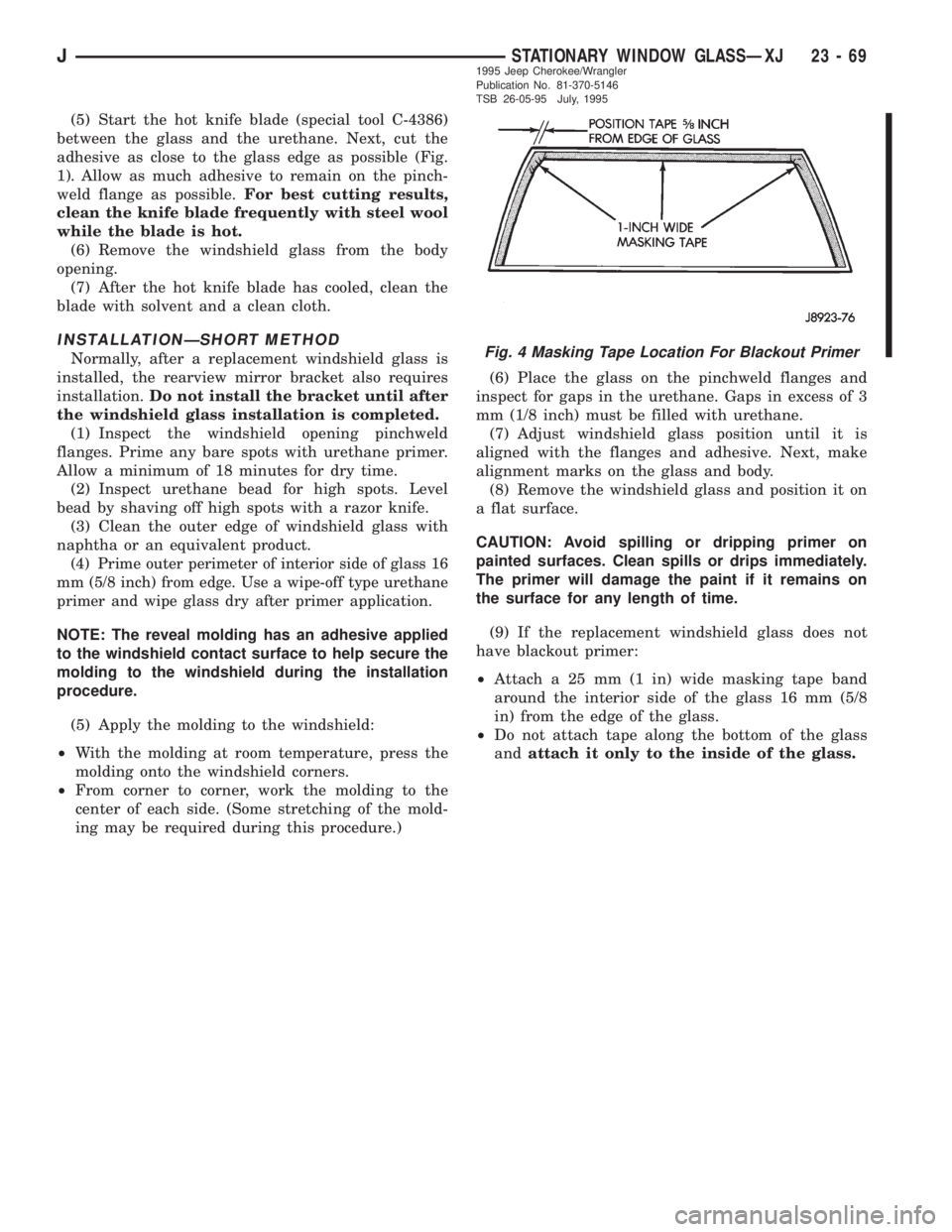
²Attach a 25 mm (1 in) wide masking tape band
around the interior side of the glass 16 mm (5/8
in) from the edge of the glass.
²Do not attach tape along the bottom of the glass
andattach it only to the inside of the glass.
Fig. 4 Masking Tape Location For Blackout Primer
JSTATIONARY WINDOW GLASSÐXJ 23 - 691995 Jeep Cherokee/Wrangler
Publication No. 81-370-5146
TSB 26-05-95 July, 1995
Page 1989 of 2158
INSTALLATIONÐEXTENDED METHOD
Normally, after a windshield is installed, the rear-
view mirror bracket also requires installation.Do
not install the bracket until after the wind-
shield installation is completed.
(1) Remove all of the urethane from all pinchweld
flanges. Use an electric hot knife and a plow-type
knife blade to remove the adhesive.
(2) Inspect and repair the windshield opening and
pinchweld flanges.
(3) Prime the pinchweld flanges with a urethane
base primer. However, if the flange is color-coated
with paint, prime the flanges with a paint finish
primer.This is important because urethane ad-
hesive will not adhere to all color-coat paints.
Allow primer sufficient time to dry.
NOTE: The reveal molding has an adhesive applied
to the windshield contact surface to help secure the
molding to the windshield during the installation
procedure.
(4) Apply the reveal molding to the windshield:
²With the molding at room temperature, press the
molding onto the windshield corners.
²From corner to corner, work the molding to the
center of each side. (Some stretching of the mold-
ing may be required during this procedure).(5) Install and inspect the fit of the windshield on
the pinchweld flanges as follows:
²Position windshield until it is aligned within wind-
shield opening.
²
Measure the gap between the pinchweld flanges
and glass around perimeter of the glass and flange.
²The reveal molding should equally cover the A-Pil-
lars on both sides.
²The flanges should also extend above the glass
edge equally around the perimeter of the opening.
Fig. 7 Applicator Nozzle Preparation
JSTATIONARY WINDOW GLASSÐXJ 23 - 711995 Jeep Cherokee/Wrangler
Publication No. 81-370-5146
TSB 26-05-95 July, 1995
Page 2000 of 2158
(2) For power seats, position seat control on seat
track/platform. Install retaining screws. Tighten
screws securely.
(3) Position cover on seatback. Install cover re-
tainer clips.
(4) Attach cover bottom elastic band or attach Vel-
cro flap to front of cover.
(5) Install seatback insert.
(6) Install headrest latch release lever bezel.
(7) Install headrest by pushing it down into seat-
back cylinders.
(8) Install cushion on frame. If necessary, refer to
installation procedure.
(9) Install seat in the vehicle. If necessary, refer to
the installation procedure.
(10) For power seats, test seat operation.
BUCKET SEAT PLATFORMÐXJ
REPLACEMENT
Bucket seat platforms are not repairable. If the
seat platform is damaged, replace platform as a unit.
REAR SEAT CUSHIONÐXJ
REMOVAL
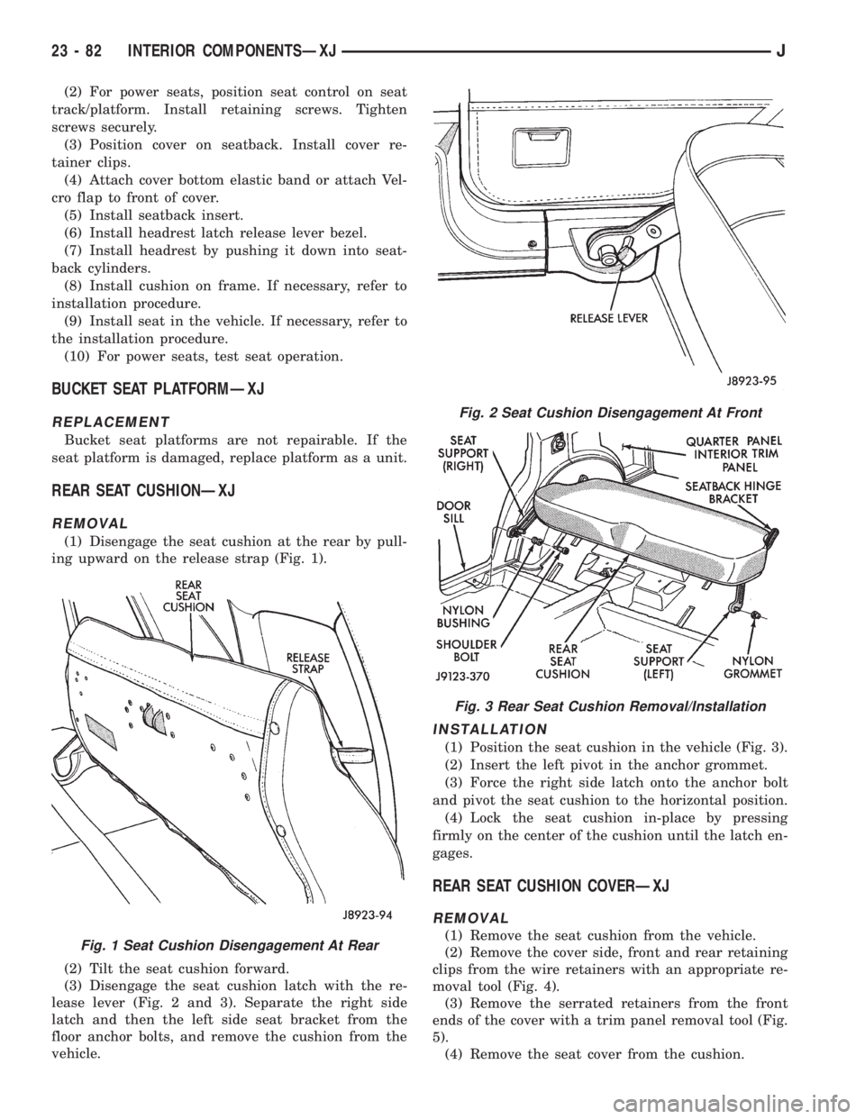
(1) Disengage the seat cushion at the rear by pull-
ing upward on the release strap (Fig. 1).
(2) Tilt the seat cushion forward.
(3) Disengage the seat cushion latch with the re-
lease lever (Fig. 2 and 3). Separate the right side
latch and then the left side seat bracket from the
floor anchor bolts, and remove the cushion from the
vehicle.
INSTALLATION
(1) Position the seat cushion in the vehicle (Fig. 3).
(2) Insert the left pivot in the anchor grommet.
(3) Force the right side latch onto the anchor bolt
and pivot the seat cushion to the horizontal position.
(4) Lock the seat cushion in-place by pressing
firmly on the center of the cushion until the latch en-
gages.
REAR SEAT CUSHION COVERÐXJ
REMOVAL
(1) Remove the seat cushion from the vehicle.
(2) Remove the cover side, front and rear retaining
clips from the wire retainers with an appropriate re-
moval tool (Fig. 4).
(3) Remove the serrated retainers from the front
ends of the cover with a trim panel removal tool (Fig.
5).
(4) Remove the seat cover from the cushion.Fig. 1 Seat Cushion Disengagement At Rear
Fig. 2 Seat Cushion Disengagement At Front
Fig. 3 Rear Seat Cushion Removal/Installation
23 - 82 INTERIOR COMPONENTSÐXJJ
Page 2023 of 2158
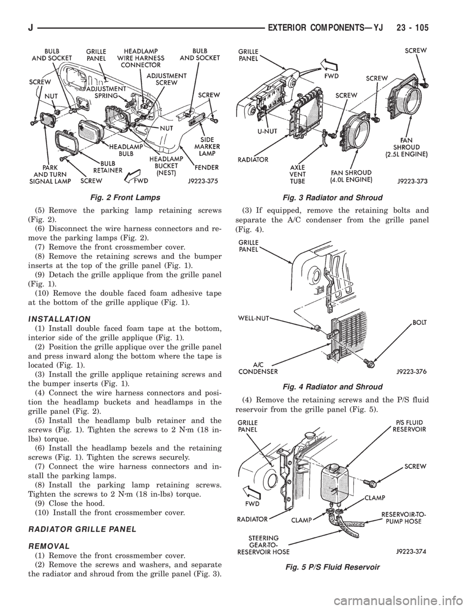
(5) Remove the parking lamp retaining screws
(Fig. 2).
(6) Disconnect the wire harness connectors and re-
move the parking lamps (Fig. 2).
(7) Remove the front crossmember cover.
(8) Remove the retaining screws and the bumper
inserts at the top of the grille panel (Fig. 1).
(9) Detach the grille applique from the grille panel
(Fig. 1).
(10) Remove the double faced foam adhesive tape
at the bottom of the grille applique (Fig. 1).
INSTALLATION
(1) Install double faced foam tape at the bottom,
interior side of the grille applique (Fig. 1).
(2) Position the grille applique over the grille panel
and press inward along the bottom where the tape is
located (Fig. 1).
(3) Install the grille applique retaining screws and
the bumper inserts (Fig. 1).
(4) Connect the wire harness connectors and posi-
tion the headlamp buckets and headlamps in the
grille panel (Fig. 2).
(5) Install the headlamp bulb retainer and the
screws (Fig. 1). Tighten the screws to 2 Nzm (18 in-
lbs) torque.
(6) Install the headlamp bezels and the retaining
screws (Fig. 1). Tighten the screws securely.
(7) Connect the wire harness connectors and in-
stall the parking lamps.
(8) Install the parking lamp retaining screws.
Tighten the screws to 2 Nzm (18 in-lbs) torque.
(9) Close the hood.
(10) Install the front crossmember cover.
RADIATOR GRILLE PANEL
REMOVAL
(1) Remove the front crossmember cover.
(2) Remove the screws and washers, and separate
the radiator and shroud from the grille panel (Fig. 3).(3) If equipped, remove the retaining bolts and
separate the A/C condenser from the grille panel
(Fig. 4).
(4) Remove the retaining screws and the P/S fluid
reservoir from the grille panel (Fig. 5).
Fig. 2 Front LampsFig. 3 Radiator and Shroud
Fig. 4 Radiator and Shroud
Fig. 5 P/S Fluid Reservoir
JEXTERIOR COMPONENTSÐYJ 23 - 105
Page 2043 of 2158
(8) Separate the liftgate glass from the hard top.
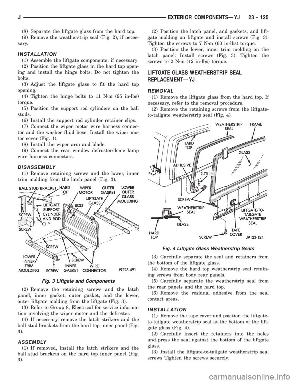
(9) Remove the weatherstrip seal (Fig. 2), if neces-
sary.
INSTALLATION
(1) Assemble the liftgate components, if necessary
(2) Position the liftgate glass in the hard top open-
ing and install the hinge bolts. Do not tighten the
bolts.
(3) Adjust the liftgate glass to fit the hard top
opening.
(4) Tighten the hinge bolts to 11 Nzm (95 in-lbs)
torque.
(5) Position the support rod cylinders on the ball
studs.
(6) Install the support rod cylinder retainer clips.
(7) Connect the wiper motor wire harness connec-
tor and the washer fluid hose. Install the wiper mo-
tor cover (Fig. 1).
(8) Install the wiper arm and blade.
(9) Connect the rear window defroster/dome lamp
wire harness connectors.
DISASSEMBLY
(1) Remove retaining screws and the lower, inner
trim molding from the latch panel (Fig. 3).
(2) Remove the retaining screws and the latch
panel, inner gasket, outer gasket, and the lower,
outer liftgate molding from the liftgate (Fig. 3).
(3) Refer to Group 8, Electrical for service informa-
tion involving the wiper motor and the defroster.
(4) If necessary, remove the latch strikers and the
ball stud brackets from the hard top inner panel (Fig.
3).
ASSEMBLY
(1) If removed, install the latch strikers and the
ball stud brackets on the hard top inner panel (Fig.
3).(2) Position the latch panel, and gaskets, and lift-
gate molding on liftgate and install screws (Fig. 3).
Tighten the screws to 7 Nzm (60 in-lbs) torque.
(3) Position the lower, inner trim molding on the
latch panel. Install screws (Fig. 3). Tighten the
screws to 2 Nzm (12 in-lbs) torque.
LIFTGATE GLASS WEATHERSTRIP SEAL
REPLACEMENTÐYJ
REMOVAL
(1) Remove the liftgate glass from the hard top. If
necessary, refer to the removal procedure.
(2) Remove the retaining screws from the liftgate-
to-tailgate weatherstrip seal (Fig. 4).
(3) Carefully separate the seal and retainers from
the bottom of the liftgate glass.
(4) Remove the hard top weatherstrip seal retain-
ing screws from body rear panels.
(5) Carefully separate the weatherstrip seal from
the rear panels and the hard top.
(6) Remove the residual adhesive from the seal
contact areas.
INSTALLATION
(1) Remove the tape cover and position the liftgate-
to-tailgate weatherstrip seal at the bottom of the lift-
gate glass (Fig. 4).
(2) Carefully insert the retainers into the holes
and press the seal against the bottom of the liftgate
glass.
(3) Install the liftgate-to-tailgate weatherstrip seal
screws Tighten the screws securely.
Fig. 3 Liftgate and Components
Fig. 4 Liftgate Glass Weatherstrip Seals
JEXTERIOR COMPONENTSÐYJ 23 - 125
Page 2044 of 2158
(4) Apply weatherstrip adhesive to the hard top
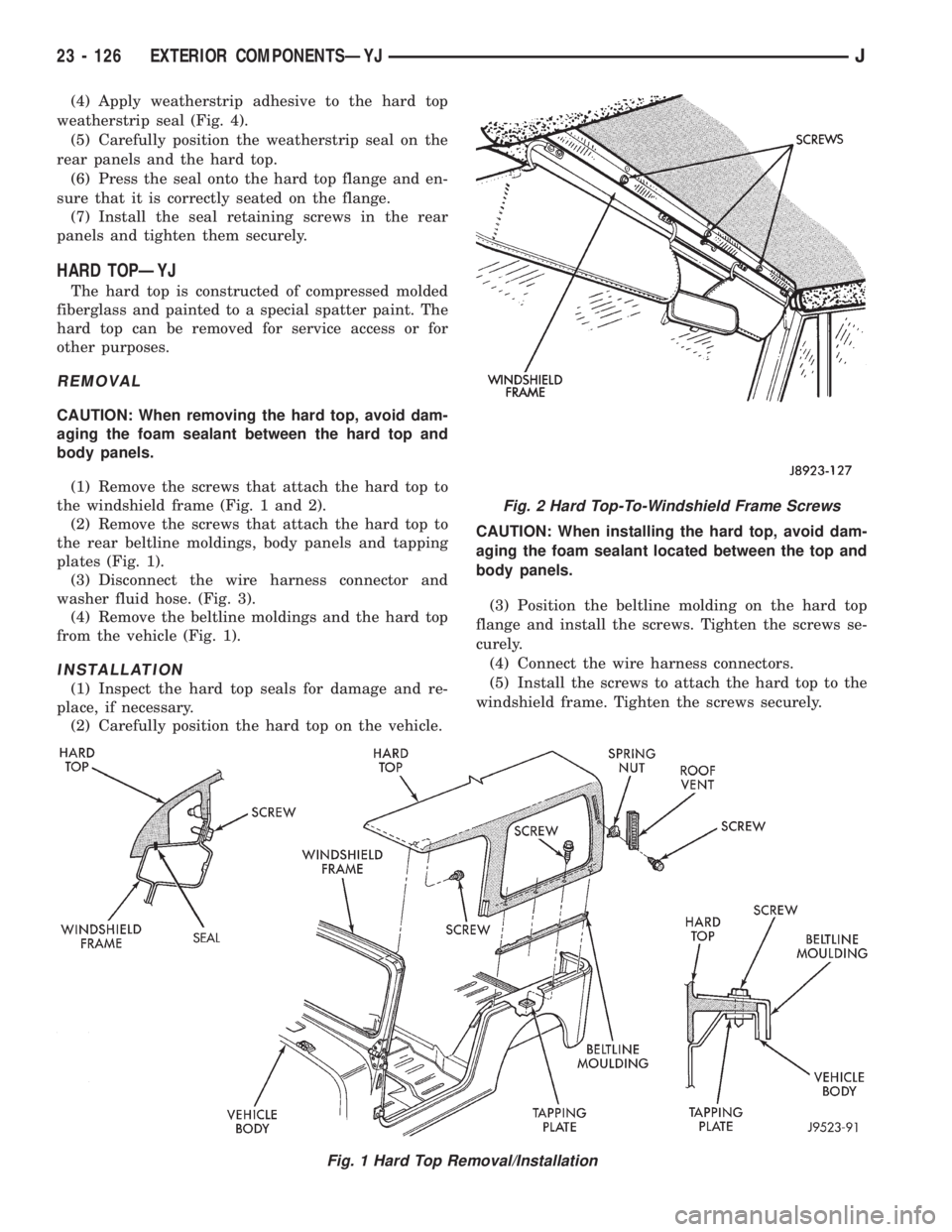
weatherstrip seal (Fig. 4).
(5) Carefully position the weatherstrip seal on the
rear panels and the hard top.
(6) Press the seal onto the hard top flange and en-
sure that it is correctly seated on the flange.
(7) Install the seal retaining screws in the rear
panels and tighten them securely.
HARD TOPÐYJ
The hard top is constructed of compressed molded
fiberglass and painted to a special spatter paint. The
hard top can be removed for service access or for
other purposes.
REMOVAL
CAUTION: When removing the hard top, avoid dam-
aging the foam sealant between the hard top and
body panels.
(1) Remove the screws that attach the hard top to
the windshield frame (Fig. 1 and 2).
(2) Remove the screws that attach the hard top to
the rear beltline moldings, body panels and tapping
plates (Fig. 1).
(3) Disconnect the wire harness connector and
washer fluid hose. (Fig. 3).
(4) Remove the beltline moldings and the hard top
from the vehicle (Fig. 1).
INSTALLATION
(1) Inspect the hard top seals for damage and re-
place, if necessary.
(2) Carefully position the hard top on the vehicle.CAUTION: When installing the hard top, avoid dam-
aging the foam sealant located between the top and
body panels.
(3) Position the beltline molding on the hard top
flange and install the screws. Tighten the screws se-
curely.
(4) Connect the wire harness connectors.
(5) Install the screws to attach the hard top to the
windshield frame. Tighten the screws securely.
Fig. 1 Hard Top Removal/Installation
Fig. 2 Hard Top-To-Windshield Frame Screws
23 - 126 EXTERIOR COMPONENTSÐYJJ
Page 2052 of 2158
DOORS
INDEX
page page
Beltline SealÐYJ........................ 142
Door Frame Glass Channel ReplacementÐYJ . . . 142
Door Weatherstrip Seal ReplacementÐYJ...... 142
Full-Metal Door Assist HandleÐYJ........... 136
Full-Metal Door HingesÐYJ................ 140
Full-Metal Door Key Lock CylinderÐYJ........ 139
Full-Metal Door Latch External Release
HandleÐYJ........................... 140
Full-Metal Door Latch Inside Release and Lock
HandleÐYJ........................... 137
Full-Metal Door LatchÐYJ.................. 140Full-Metal Door ServiceÐYJ................ 142
Full-Metal Door Trim PanelÐYJ.............. 137
Full-Metal Door Vent Window GlassÐYJ....... 137
Full-Metal Door WaterdamÐYJ.............. 137
Full-Metal Door Weatherstrip SealsÐYJ........ 141
Full-Metal Door Window Glass Regulator
HandleÐYJ........................... 136
Full-Metal Door Window Glass RegulatorÐYJ . . . 138
Full-Metal Door Window GlassÐYJ........... 139
Half-Metal Door Latch StrikerÐYJ............ 135
Half-Metal Soft Top DoorÐYJ............... 134
HALF-METAL SOFT TOP DOORÐYJ
REMOVAL/DISASSEMBLY
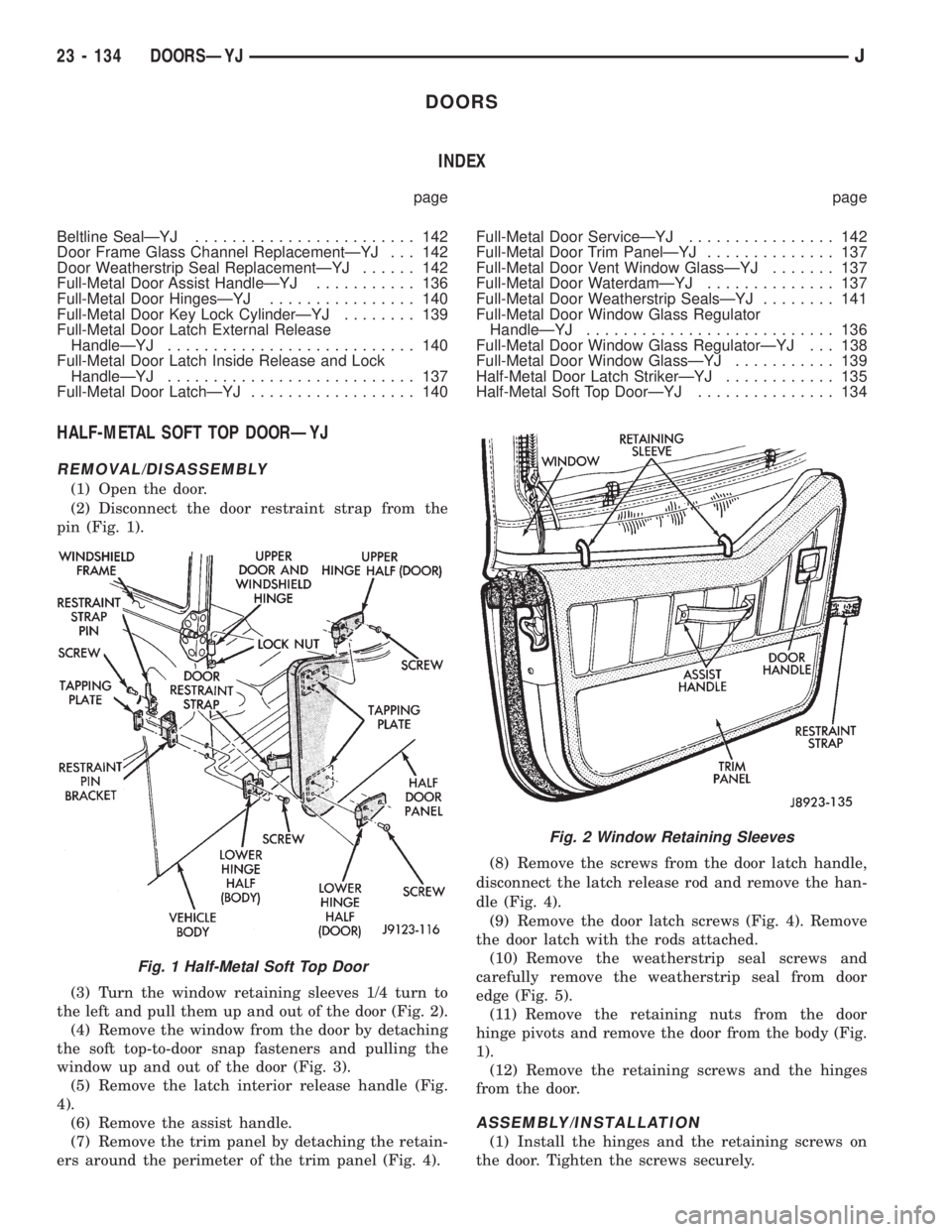
(1) Open the door.
(2) Disconnect the door restraint strap from the
pin (Fig. 1).
(3) Turn the window retaining sleeves 1/4 turn to
the left and pull them up and out of the door (Fig. 2).
(4) Remove the window from the door by detaching
the soft top-to-door snap fasteners and pulling the
window up and out of the door (Fig. 3).
(5) Remove the latch interior release handle (Fig.
4).
(6) Remove the assist handle.
(7) Remove the trim panel by detaching the retain-
ers around the perimeter of the trim panel (Fig. 4).(8) Remove the screws from the door latch handle,
disconnect the latch release rod and remove the han-
dle (Fig. 4).
(9) Remove the door latch screws (Fig. 4). Remove
the door latch with the rods attached.
(10) Remove the weatherstrip seal screws and
carefully remove the weatherstrip seal from door
edge (Fig. 5).
(11) Remove the retaining nuts from the door
hinge pivots and remove the door from the body (Fig.
1).
(12) Remove the retaining screws and the hinges
from the door.
ASSEMBLY/INSTALLATION
(1) Install the hinges and the retaining screws on
the door. Tighten the screws securely.
Fig. 1 Half-Metal Soft Top Door
Fig. 2 Window Retaining Sleeves
23 - 134 DOORSÐYJJ