1995 JEEP YJ ignition
[x] Cancel search: ignitionPage 447 of 2158
OK, replace pump. If not OK, repair open between
switch connector and pump connector.
WITH INTERMITTENT WIPE
(1) Measure resistance from washer pump connec-
tor terminal B to a clean chassis ground. Meter
should read zero ohms. If not OK, repair open be-
tween terminal B and ground.
(2) Turn ignition switch to ON and rotate washer
switch tab forward.
(a) Measure voltage at wiper/washer switch con-
nector terminal B located at intermittent wipe
module. Meter should read battery voltage. If not
OK, replace wiper switch.(b) Measure voltage at intermittent wipe module
connector terminal B (to washer pump). Meter
should read battery voltage. If not OK, replace in-
termittent wipe module.
(c) Measure voltage at washer pump connector
terminal A. Meter should read battery voltage. If
OK, replace pump. If not OK, repair open from in-
termittent wipe module connector terminal B.
WINDSHIELD WIPER/WASHER SWITCH
To test windshield wiper/washer switches, perform
the resistance tests shown in the following charts. If
switch fails any test, replace faulty switch.
JWIPER AND WASHER SYSTEMS - YJ 8K - 13
Page 450 of 2158

LIFTGATE WIPER/WASHER SYSTEM
(1) Turn ignition switch to ON and liftgate wiper/
washer switch to WASH.
(a) Measure voltage at switch connector terminal
P. Meter should read battery voltage. If not OK,
check fuse 1.
(b) Measure voltage at switch connector terminal
B. Meter should read battery voltage. If not OK, re-
place switch.
(c) Measure voltage at switch connector terminal
A. Meter should read battery voltage. If not OK, re-
place switch.
(2) Unplug liftgate washer pump connector.
(a) With ignition switch in OFF position, mea-
sure resistance at pump connector black wire to
ground. Meter should read zero ohms. If not OK,
repair open to ground.
(b) With ignition switch in ON position, measure
voltage at pump connector brown/white wire,
switch in WASH. Meter should read battery volt-
age. If OK, replace pump. If not OK, check wiring.
(3) Turn ignition switch to ON, unplug liftgate
wiper motor connector and place wiper switch in
WIPE.
(a) Measure resistance at motor connector termi-
nal B to ground. Meter should read zero ohms. If
not OK, repair open to ground.
(b) Measure voltage at motor connector terminal
A. Meter should read battery voltage. If not OK,
check wiring to fuse.
(c) Measure voltage at motor connector terminal
C. Meter should read battery voltage. If OK, re-
place motor. If not OK, repair open to switch.
LIFTGATE WIPER/WASHER SWITCH
See Liftgate Wiper/Washer Switch Diagram (Fig. 1)
and Liftgate Wiper Switch Tests (Fig. 2). Check
switch continuity and resistance accordingly. If
switch fails any test, replace faulty switch.
Fig. 1 Liftgate Wiper/Washer Switch Diagram
Fig. 2 Liftgate Wiper/Washer Switch Tests
8K - 16 WIPER AND WASHER SYSTEMS - YJJ
Page 454 of 2158
LIFTGATE WIPER MOTOR REMOVE/INSTALL
(1) Remove wiper arm from motor (see Liftgate
Wiper Arm Remove/Install).
(2) Remove pivot shaft retaining nut.
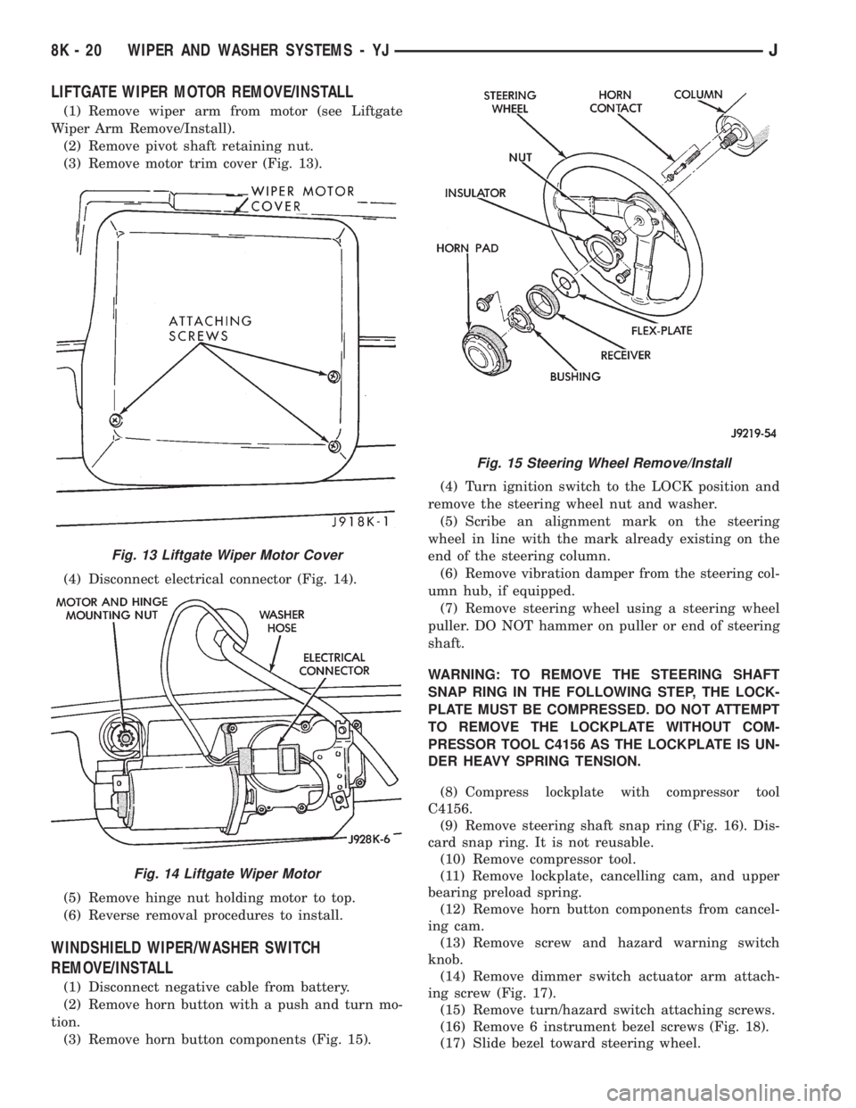
(3) Remove motor trim cover (Fig. 13).
(4) Disconnect electrical connector (Fig. 14).
(5) Remove hinge nut holding motor to top.
(6) Reverse removal procedures to install.
WINDSHIELD WIPER/WASHER SWITCH
REMOVE/INSTALL
(1) Disconnect negative cable from battery.
(2) Remove horn button with a push and turn mo-
tion.
(3) Remove horn button components (Fig. 15).(4) Turn ignition switch to the LOCK position and
remove the steering wheel nut and washer.
(5) Scribe an alignment mark on the steering
wheel in line with the mark already existing on the
end of the steering column.
(6) Remove vibration damper from the steering col-
umn hub, if equipped.
(7) Remove steering wheel using a steering wheel
puller. DO NOT hammer on puller or end of steering
shaft.
WARNING: TO REMOVE THE STEERING SHAFT
SNAP RING IN THE FOLLOWING STEP, THE LOCK-
PLATE MUST BE COMPRESSED. DO NOT ATTEMPT
TO REMOVE THE LOCKPLATE WITHOUT COM-
PRESSOR TOOL C4156 AS THE LOCKPLATE IS UN-
DER HEAVY SPRING TENSION.
(8) Compress lockplate with compressor tool
C4156.
(9) Remove steering shaft snap ring (Fig. 16). Dis-
card snap ring. It is not reusable.
(10) Remove compressor tool.
(11) Remove lockplate, cancelling cam, and upper
bearing preload spring.
(12) Remove horn button components from cancel-
ing cam.
(13) Remove screw and hazard warning switch
knob.
(14) Remove dimmer switch actuator arm attach-
ing screw (Fig. 17).
(15) Remove turn/hazard switch attaching screws.
(16) Remove 6 instrument bezel screws (Fig. 18).
(17) Slide bezel toward steering wheel.
Fig. 13 Liftgate Wiper Motor Cover
Fig. 14 Liftgate Wiper Motor
Fig. 15 Steering Wheel Remove/Install
8K - 20 WIPER AND WASHER SYSTEMS - YJJ
Page 456 of 2158
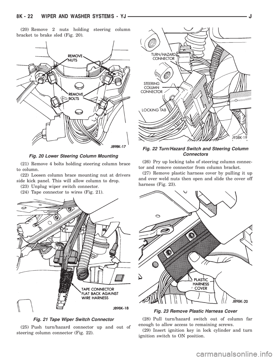
(20) Remove 2 nuts holding steering column
bracket to brake sled (Fig. 20).
(21) Remove 4 bolts holding steering column brace
to column.
(22) Loosen column brace mounting nut at drivers
side kick panel. This will allow column to drop.
(23) Unplug wiper switch connector.
(24) Tape connector to wires (Fig. 21).
(25) Push turn/hazard connector up and out of
steering column connector (Fig. 22).(26) Pry up locking tabs of steering column connec-
tor and remove connector from column bracket.
(27) Remove plastic harness cover by pulling it up
and over weld nuts then open and slide the cover off
harness (Fig. 23).
(28) Pull turn/hazard switch out of column far
enough to allow access to remaining screws.
(29) Insert ignition key in lock cylinder and turn
ignition switch to ON position.
Fig. 20 Lower Steering Column Mounting
Fig. 21 Tape Wiper Switch Connector
Fig. 22 Turn/Hazard Switch and Steering Column
Connectors
Fig. 23 Remove Plastic Harness Cover
8K - 22 WIPER AND WASHER SYSTEMS - YJJ
Page 457 of 2158
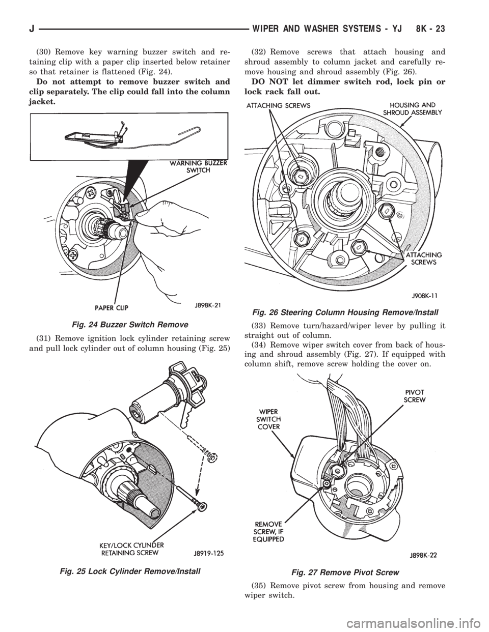
(30) Remove key warning buzzer switch and re-
taining clip with a paper clip inserted below retainer
so that retainer is flattened (Fig. 24).
Do not attempt to remove buzzer switch and
clip separately. The clip could fall into the column
jacket.
(31) Remove ignition lock cylinder retaining screw
and pull lock cylinder out of column housing (Fig. 25)(32) Remove screws that attach housing and
shroud assembly to column jacket and carefully re-
move housing and shroud assembly (Fig. 26).
DO NOT let dimmer switch rod, lock pin or
lock rack fall out.
(33) Remove turn/hazard/wiper lever by pulling it
straight out of column.
(34) Remove wiper switch cover from back of hous-
ing and shroud assembly (Fig. 27). If equipped with
column shift, remove screw holding the cover on.
(35) Remove pivot screw from housing and remove
wiper switch.
Fig. 24 Buzzer Switch Remove
Fig. 25 Lock Cylinder Remove/Install
Fig. 26 Steering Column Housing Remove/Install
Fig. 27 Remove Pivot Screw
JWIPER AND WASHER SYSTEMS - YJ 8K - 23
Page 474 of 2158
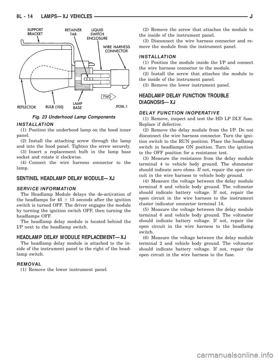
INSTALLATION
(1) Position the underhood lamp on the hood inner
panel.
(2) Install the attaching screw through the lamp
and into the hood panel. Tighten the screw securely.
(3) Insert a replacement bulb in the lamp base
socket and rotate it clockwise.
(4) Connect the wire harness connector to the
lamp.
SENTINEL HEADLAMP DELAY MODULEÐXJ
SERVICE INFORMATION
The Headlamp Module delays the de-activation of
the headlamps for 45615 seconds after the ignition
switch is turned OFF. The driver engages the module
by turning the ignition switch OFF, then turning the
headlamps OFF.
The headlamp delay module is located behind the
I/P next to the headlamp switch.
HEADLAMP DELAY MODULE REPLACEMENTÐXJ
The headlamp delay module is attached to the in-
side of the instrument panel to the right of the head-
lamp switch.
REMOVAL
(1) Remove the lower instrument panel.(2) Remove the screw that attaches the module to
the inside of the instrument panel.
(3) Disconnect the wire harness connector and re-
move the module from the instrument panel.
INSTALLATION
(1) Position the module inside the I/P and connect
the wire harness connector to the module.
(2) Install the screw that attaches the module to
the inside of the instrument panel.
(3) Remove the lower instrument panel.
HEADLAMP DELAY FUNCTION TROUBLE
DIAGNOSISÐXJ
DELAY FUNCTION INOPERATIVE
(1) Remove, inspect and test the HD LP DLY fuse.
Replace if defective.
(2) Remove the delay module from the I/P. Do not
disconnect the wire harness connector. Turn the igni-
tion switch to the RUN position. Place the headlamp
switch in headlamps ON position. Turn the ignition
to the OFF position for a resistance test.
(3) Measure the resistance from the delay module
terminal 4 to vehicle body ground. The ohmmeter
should indicate zero ohms. If not, repair the open cir-
cuit in the wire harness to vehicle body ground.
(4) Measure the voltage between the delay module
terminal 8 and vehicle body ground. The voltmeter
should indicate battery voltage. If not, repair the
open circuit in the wire harness to the instrument
cluster indicator connector terminal 14.
(5) Measure the voltage between the delay module
terminal 6 and vehicle body ground. The voltmeter
should indicate battery voltage. If not, repair the
open circuit in the wire harness to the headlamp
switch.
(6) Measure the voltage between the delay module
terminal 2 and vehicle body ground. The voltmeter
should indicate battery voltage. If not, repair the
open circuit in the wire harness to the fuse.Fig. 23 Underhood Lamp Components
8L - 14 LAMPSÐXJ VEHICLESJ
Page 475 of 2158

DAYTIME RUNNING LIGHTS (CANADA ONLY)ÐXJ
SERVICE INFORMATION
The Daytime Running Lights (Headlamps) System
is installed on vehicles manufactured for sale in Can-
ada only. The headlamps are illuminated when the
ignition switch is turned to the ON position. The
DRL module receives a vehicle-moving signal from
the vehicle speed sensor. This provides a constant
headlamps-oncondition as long as the vehicle is
moving. The lamps are illuminated at less than 50
percent of normal intensity.
DRL MODULE REPLACEMENTÐXJ
REMOVAL
The Daytime Running Lights (DRL) module is lo-
cated on the right fender inner panel adjacent to the
dash panel (Fig. 24).
(1) Disconnect the wire harness connector from the
module.
(2) Remove the screws that attach the module to
the fender inner panel.
(3) Remove the module from the fender inner
panel.
INSTALLATION
(1) Position the module on the right fender inner
panel.
(2) Install the attaching screws. Tighten the
screws securely.(3) Connect the wire harness connector to the mod-
ule.
Fig. 24 Daytime Running Lights (DRL) Module
JLAMPSÐXJ VEHICLES 8L - 15
Page 490 of 2158

(3) Insert a replacement bulb in the lamp base
socket and rotate it clockwise.
(4) Connect the wire harness connector to the
lamp.
DAYTIME RUNNING LIGHTS (CANADA ONLY)ÐYJ
The Daytime Running Lights (Headlamps) System
is installed on vehicles manufactured for sale in Can-
ada only. The headlamps are illuminated when the
ignition switch is turned to the ON position. The
DRL module receives a vehicle-moving signal from
the vehicle speed sensor. This provides a constant
headlamps-oncondition as long as the vehicle is
moving. The lamps are illuminated at less than 50
percent of normal intensity.
DRL MODULE REPLACEMENTÐYJ
REMOVAL
The daytime running light module is located on the
left fender inner panel below the engine air cleaner
housing.
(1) Remove the engine air cleaner housing for ac-
cess to the DRL module.
(2) Disconnect the wire harness connector from the
module.
(3) Remove the screws that attach the module to
the fender inner panel (Fig. 21).(4) Remove the module from the fender inner
panel.
INSTALLATION
(1) Position the DRL module on the left, fender in-
ner panel.
(2) Install the attaching screws. Tighten the
screws securely.
(3) Connect the wire harness connector to the mod-
ule.
(4) Install the air cleaner housing.
Fig. 21 Daytime Running Lamp Module
8L - 30 LAMPSÐYJ VEHICLESJ