1995 JEEP YJ ignition
[x] Cancel search: ignitionPage 532 of 2158
DIAGNOSIS
BUZZER MODULE
(1) Check fuses (15 and 17 - XJ, 3 and 9 - YJ) in
the fuseblock module. If fuses are OK, go to next
step. If not OK, replace fuses as required.
(2) Check for battery voltage at fuse (15 - XJ, 3 -
YJ) in fuseblock module. If OK, go to next step. If not
OK, repair feed circuit from power distribution center
as required.
(3) Turn ignition switch to ON position. Check for
battery voltage at fuse (17 - XJ, 9 - YJ) in the fuse-
block module. If OK, go to next step. If not OK, re-
pair feed from ignition switch as required.
(4) Turn ignition switch to OFF position. Replace
buzzer module with a known good unit and test op-
eration. If not OK, remove buzzer module and go to
next step.
(5) Check for battery voltage at cavity for buzzer
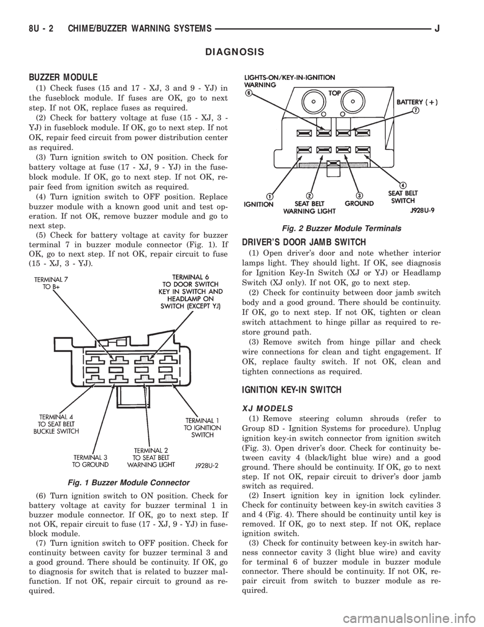
terminal 7 in buzzer module connector (Fig. 1). If
OK, go to next step. If not OK, repair circuit to fuse
(15 - XJ, 3 - YJ).
(6) Turn ignition switch to ON position. Check for
battery voltage at cavity for buzzer terminal 1 in
buzzer module connector. If OK, go to next step. If
not OK, repair circuit to fuse (17 - XJ, 9 - YJ) in fuse-
block module.
(7) Turn ignition switch to OFF position. Check for
continuity between cavity for buzzer terminal 3 and
a good ground. There should be continuity. If OK, go
to diagnosis for switch that is related to buzzer mal-
function. If not OK, repair circuit to ground as re-
quired.
DRIVER'S DOOR JAMB SWITCH
(1) Open driver's door and note whether interior
lamps light. They should light. If OK, see diagnosis
for Ignition Key-In Switch (XJ or YJ) or Headlamp
Switch (XJ only). If not OK, go to next step.
(2) Check for continuity between door jamb switch
body and a good ground. There should be continuity.
If OK, go to next step. If not OK, tighten or clean
switch attachment to hinge pillar as required to re-
store ground path.
(3) Remove switch from hinge pillar and check
wire connections for clean and tight engagement. If
OK, replace faulty switch. If not OK, clean and
tighten connections as required.
IGNITION KEY-IN SWITCH
XJ MODELS
(1) Remove steering column shrouds (refer to
Group 8D - Ignition Systems for procedure). Unplug
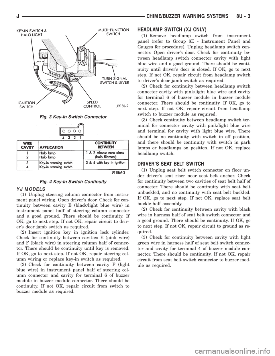
ignition key-in switch connector from ignition switch
(Fig. 3). Open driver's door. Check for continuity be-
tween cavity 4 (black/light blue wire) and a good
ground. There should be continuity. If OK, go to next
step. If not OK, repair circuit to driver's door jamb
switch as required.
(2) Insert ignition key in ignition lock cylinder.
Check for continuity between key-in switch cavities 3
and 4 (Fig. 4). There should be continuity until key is
removed. If OK, go to next step. If not OK, replace
ignition switch.
(3) Check for continuity between key-in switch har-
ness connector cavity 3 (light blue wire) and cavity
for terminal 6 of buzzer module in buzzer module
connector. There should be continuity. If not OK, re-
pair circuit from switch to buzzer module as re-
quired.
Fig. 1 Buzzer Module Connector
Fig. 2 Buzzer Module Terminals
8U - 2 CHIME/BUZZER WARNING SYSTEMSJ
Page 533 of 2158
YJ MODELS
(1) Unplug steering column connector from instru-
ment panel wiring. Open driver's door. Check for con-
tinuity between cavity E (black/light blue wire) in
instrument panel half of steering column connector
and a good ground. There should be continuity. If
OK, go to next step. If not OK, repair circuit to driv-
er's door jamb switch as required.
(2) Insert ignition key in ignition lock cylinder.
Check for continuity between cavities E (pink wire)
and F (black wire) in steering column half of connec-
tor. There should be continuity until key is removed.
If OK, go to next step. If not OK, repair steering col-
umn wiring or replace key-in switch as required.
(3) Check for continuity between cavity F (light
blue wire) in instrument panel half of steering col-
umn connector and cavity for terminal 6 of buzzer
module in buzzer module connector. There should be
continuity. If not OK, repair circuit from switch to
buzzer module as required.
HEADLAMP SWITCH (XJ ONLY)
(1) Remove headlamp switch from instrument
panel (refer to Group 8E - Instrument Panel and
Gauges for procedure). Unplug headlamp switch con-
nector. Open driver's door. Check for continuity be-
tween headlamp switch connector cavity with light
blue wire and a good ground. There should be conti-
nuity until driver's door is closed. If OK, go to next
step. If not OK, repair circuit from headlamp switch
to driver's door jamb switch as required.
(2) Check for continuity between headlamp switch
connector cavity with pink/light blue wire and cavity
for terminal 6 of buzzer module in buzzer module
connector. There should be continuity. If OK, go to
next step. If not OK, repair circuit from headlamp
switch to buzzer module as required.
(3) Check continuity between headlamp switch ter-
minal for connector cavity with pink/light blue wire
and terminal for cavity with light blue wire. There
should be no continuity with switch in off position,
and there should be continuity with switch in park
lamps or headlamps on position. If not OK, replace
headlamp switch.
DRIVER'S SEAT BELT SWITCH
(1) Unplug seat belt switch connector on floor un-
der driver's seat riser near seat belt anchor. Check
for continuity between two cavities of seat belt half of
connector. There should be continuity with seat belt
unbuckled, and no continuity with seat belt buckled.
If OK, go to next step. If not OK, replace seat belt
buckle-half assembly.
(2) Check for continuity between cavity with black
wire in harness half of seat belt switch connector and
a good ground. There should be continuity. If OK, go
to next step. If not OK, repair circuit to ground as re-
quired.
(3) Check for continuity between cavity with light
green wire in harness half of seat belt switch connec-
tor and cavity for terminal 4 of buzzer module con-
nector. There should be continuity. If not OK, repair
circuit from seat belt switch connector to buzzer mod-
ule as required.
Fig. 3 Key-In Switch Connector
Fig. 4 Key-In Switch Continuity
JCHIME/BUZZER WARNING SYSTEMS 8U - 3
Page 534 of 2158
SERVICE PROCEDURES
Service procedures for components of the buzzer
system can be found in the appropriate group as fol-
lows:
²driver's door jamb switch - refer to Group 8L -
Lamps
²ignition key-in switch (XJ) - refer to Group 8D -
Ignition Systems²ignition key-in switch (YJ) - refer to Group 19 -
Steering
²headlamp switch - refer to Group 8E - Instrument
Panel and Gauges
²driver's seat belt switch - refer to Group 23 - Body
Components.
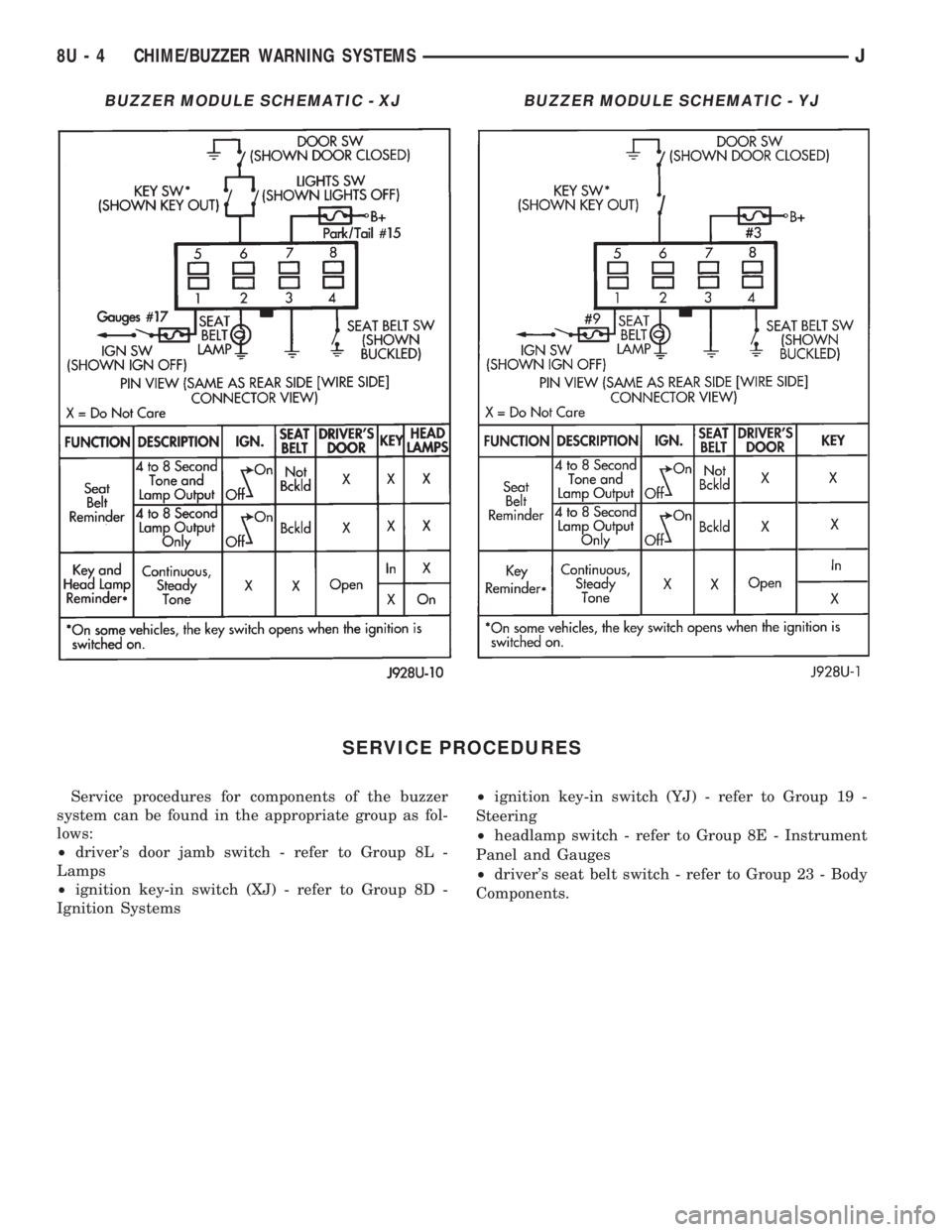
BUZZER MODULE SCHEMATIC - XJBUZZER MODULE SCHEMATIC - YJ
8U - 4 CHIME/BUZZER WARNING SYSTEMSJ
Page 535 of 2158
WIRING DIAGRAMSÐGENERAL INFORMATION
INDEX
page page
Circuit Identification......................... 1
Connector and Terminal Replacement........... 7
Connector Replacement..................... 6
Connectors............................... 2
Diode Replacement........................ 8
Electrostatic Discharge (ESC) Sensitive Devices . . . 2
General Information......................... 1
Intermittent and Poor Connections.............. 4
Notes, Cautions, and Warnings................ 1Symbols................................. 2
Take Outs................................ 2
Terminal Replacement....................... 8
Terminal/Connector RepairÐMolex Connectors.... 6
Troubleshooting Tests....................... 4
Troubleshooting Tools....................... 4
Troubleshooting Wiring Problems.............. 5
Wire Code Identification..................... 1
Wiring Repair............................. 6
GENERAL INFORMATION
This Group is divided into three stand alone sec-
tions; XJ, YJ, and XJ Right Hand Drive (XJ-RHD).
Separate circuit descriptions and wiring diagrams are
provided for each vehicle. Each section contains a
Contents list for the wiring diagrams and circuit de-
scriptions for that vehicle.
The complete XJ circuit descriptions and diagrams
are printed first, followed by those for the YJ and
then the XJ-RHD. The heading at the top of each
page identifies the vehicle covered in the section.
NOTES, CAUTIONS, and WARNINGS
Throughout this group additional important infor-
mation is presented in three ways; Notes, Cautions,
and Warnings.
NOTESare used to help describe how switches or
components operate to complete a particular circuit.
They are also used to indicate different conditions
that may appear on the vehicle. For example, an
up-to and after condition.
CAUTIONSare used to indicate information that
could prevent making an error that may damage the
vehicle.
WARNINGSprovide information to prevent per-
sonal injury and vehicle damage. Below is a list of
general warnings that should be followed any time a
vehicle is being serviced.
ALWAYS WEAR SAFETY GLASSES FOR EYE PRO-
TECTION.
USE SAFETY STANDS ANYTIME A PROCEDURE RE-
QUIRES BEING UNDER A VEHICLE.
BE SURE THAT THE IGNITION SWITCH ALWAYS IS
IN THE OFF POSITION, UNLESS THE PROCEDURE
REQUIRES IT TO BE ON.SET THE PARKING BRAKE WHEN WORKING ON
ANY VEHICLE. AN AUTOMATIC TRANSMISSION
SHOULD BE IN PARK. A MANUAL TRANSMISSION
SHOULD BE IN NEUTRAL.
OPERATE THE ENGINE ONLY IN A WELL-VENTI-
LATED AREA.
KEEP AWAY FROM MOVING PARTS WHEN THE EN-
GINE IS RUNNING, ESPECIALLY THE FAN AND BELTS.
TO PREVENT SERIOUS BURNS, AVOID CONTACT
WITH HOT PARTS SUCH AS THE RADIATOR, EX-
HAUST MANIFOLD(S), TAIL PIPE, CATALYTIC CON-
VERTER, AND MUFFLER.
DO NOT ALLOW FLAME OR SPARKS NEAR THE
BATTERY. GASES ARE ALWAYS PRESENT IN AND
AROUND THE BATTERY.
ALWAYS REMOVE RINGS, WATCHES, LOOSE
HANGING JEWELRY, AND LOOSE CLOTHING.
WIRE CODE IDENTIFICATION
Each wire shown in the diagrams contains a code
(Fig. 1) which identifies the main circuit, part of the
main circuit, gauge of wire, and color. The color is
shown as a two letter code which can be identified by
referring to the Wire Color Code Chart (Fig. 2).
CIRCUIT IDENTIFICATION
All circuits in the diagrams use an alpha/numeric
code to identify the wire and its function (Fig. 3). To
identify which circuit code applies to a system, refer
to the Circuit Identification Code Chart. This chart
shows the main circuits only and does not show the
secondary codes that may apply to some models.
JWIRING DIAGRAMSÐGENERAL INFORMATION 8W - 1
Page 539 of 2158
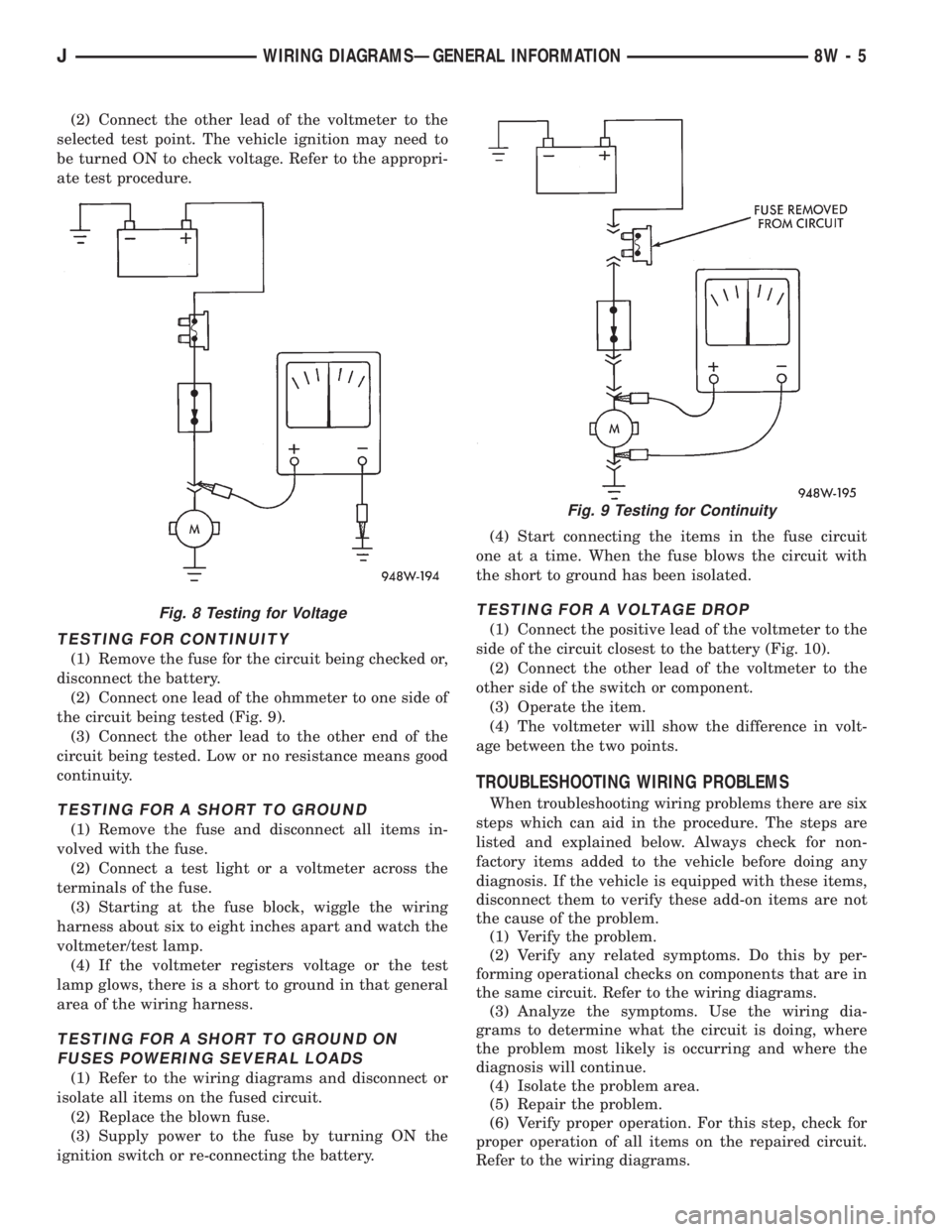
(2) Connect the other lead of the voltmeter to the
selected test point. The vehicle ignition may need to
be turned ON to check voltage. Refer to the appropri-
ate test procedure.
TESTING FOR CONTINUITY
(1) Remove the fuse for the circuit being checked or,
disconnect the battery.
(2) Connect one lead of the ohmmeter to one side of
the circuit being tested (Fig. 9).
(3) Connect the other lead to the other end of the
circuit being tested. Low or no resistance means good
continuity.
TESTING FOR A SHORT TO GROUND
(1) Remove the fuse and disconnect all items in-
volved with the fuse.
(2) Connect a test light or a voltmeter across the
terminals of the fuse.
(3) Starting at the fuse block, wiggle the wiring
harness about six to eight inches apart and watch the
voltmeter/test lamp.
(4) If the voltmeter registers voltage or the test
lamp glows, there is a short to ground in that general
area of the wiring harness.
TESTING FOR A SHORT TO GROUND ON
FUSES POWERING SEVERAL LOADS
(1) Refer to the wiring diagrams and disconnect or
isolate all items on the fused circuit.
(2) Replace the blown fuse.
(3) Supply power to the fuse by turning ON the
ignition switch or re-connecting the battery.(4) Start connecting the items in the fuse circuit
one at a time. When the fuse blows the circuit with
the short to ground has been isolated.
TESTING FOR A VOLTAGE DROP
(1) Connect the positive lead of the voltmeter to the
side of the circuit closest to the battery (Fig. 10).
(2) Connect the other lead of the voltmeter to the
other side of the switch or component.
(3) Operate the item.
(4) The voltmeter will show the difference in volt-
age between the two points.
TROUBLESHOOTING WIRING PROBLEMS
When troubleshooting wiring problems there are six
steps which can aid in the procedure. The steps are
listed and explained below. Always check for non-
factory items added to the vehicle before doing any
diagnosis. If the vehicle is equipped with these items,
disconnect them to verify these add-on items are not
the cause of the problem.
(1) Verify the problem.
(2) Verify any related symptoms. Do this by per-
forming operational checks on components that are in
the same circuit. Refer to the wiring diagrams.
(3) Analyze the symptoms. Use the wiring dia-
grams to determine what the circuit is doing, where
the problem most likely is occurring and where the
diagnosis will continue.
(4) Isolate the problem area.
(5) Repair the problem.
(6) Verify proper operation. For this step, check for
proper operation of all items on the repaired circuit.
Refer to the wiring diagrams.
Fig. 8 Testing for Voltage
Fig. 9 Testing for Continuity
JWIRING DIAGRAMSÐGENERAL INFORMATION 8W - 5
Page 543 of 2158

WIRING DIAGRAMS
CONTENTS
page page
8W-01 GENERAL INFORMATIONÐWIRING
DIAGRAMS.................... 8W-01-1
8W-10 FUSE/FUSE BLOCK........... 8W-10-1
8W-11 POWER DISTRIBUTION........ 8W-11-1
8W-15 GROUND DISTRIBUTION....... 8W-15-1
8W-20 CHARGING SYSTEM.......... 8W-20-1
8W-21 STARTING SYSTEM........... 8W-21-1
8W-30 FUEL/IGNITION.............. 8W-30-1
8W-31 TRANSMISSION CONTROLS.... 8W-31-1
8W-32 ANTI-LOCK BRAKES.......... 8W-32-1
8W-33 VEHICLE SPEED CONTROL..... 8W-33-1
8W-40 INSTRUMENT CLUSTER....... 8W-40-1
8W-41 HORN/CIGAR LIGHTER......... 8W-41-1
8W-42 AIR CONDITIONING/HEATER.... 8W-42-1
8W-44 INTERIOR LIGHTING.......... 8W-44-1
8W-47 AUDIO SYSTEM.............. 8W-47-18W-48 HEATED REAR WINDOW....... 8W-48-1
8W-49 OVERHEAD CONSOLE......... 8W-49-1
8W-50 FRONT LIGHTING............. 8W-50-1
8W-51 REAR LIGHTING............. 8W-51-1
8W-52 TURN SIGNALS.............. 8W-52-1
8W-53 WIPERS..................... 8W-53-1
8W-54 TRAILER TOW................ 8W-54-1
8W-60 POWER WINDOWS.......... 8W-60-1
8W-61 POWER DOOR LOCKS......... 8W-61-1
8W-62 POWER MIRRORS............ 8W-62-1
8W-63 POWER SEAT................ 8W-63-1
8W-70 SPLICE INFORMATION........ 8W-70-1
8W-80 CONNECTOR PIN OUTS....... 8W-80-1
8W-90 CONNECTOR LOCATIONS...... 8W-90-1
8W-95 SPLICE LOCATIONS........... 8W-95-1
HOW TO USE THIS GROUP
The purpose of this group is to show the electrical
circuits in a clear, simple fashion and to make trou-
bleshooting easier. Components that work together
are shown together. All electrical components used in
a specific system are shown on one diagram. The feed
for a system is shown at the top of the page. All
wires, connectors, splices, and components are shown
in the flow of current to the bottom of the page. Wir-
ing which is not part of the circuit represented is ref-
erenced to another page/section, where the complete
circuit is shown. In addition, all switches, compo-
nents, and modules are shown in theat rest posi-
tion with the doors closed and the key removed
from the ignition.
If a component is part of several different circuits,
it is shown in the diagram for each. For example, the
headlamp switch is the main part of the exterior
lighting, but it also affects the interior lighting and
the chime warning system.
It is important to realize that no attempt is
made on the diagrams to represent components
and wiring as they appear on the vehicle. For
example, a short piece of wire is treated the
same as a long one. In addition, switches and
other components are shown as simply as pos-
sible, with regard to function only.
The wiring diagram show circuits for all wheel-
bases. If there is a difference in systems or compo-
nents between wheel-bases, an identifier is placed
next to the component.
SECTION IDENTIFICATION
Sections in Group 8W are organized by sub-sys-
tems. The sections contain circuit operation descrip-
tions, helpful information, and system diagrams. The
intention is to organize information by system, con-
sistently from year to year.
CONNECTOR LOCATIONS
Section 8W-90 contains Connector Location illus-
trations. The illustrations contain the connector
number and component identification. Connector Lo-
cation charts in Section 8W-90 reference the illustra-
tion number for components and connectors.
Section 8W-80 shows each connector and the cir-
cuits involved with that connector. The connectors
are identified using the number on the Diagram
pages.
SPLICE LOCATIONS
Splice Location charts in Section 8W-70 show the
entire splice, and provide references to other sections
the splice serves.
Section 8W-95 contains illustrations that show the
general location of the splices in each harness. The
illustrations show the splice by number, and provide
a written location.
JWIRING DIAGRAMSÐXJ VEHICLES 8W - 1 - 1
Page 545 of 2158

FUSE/FUSE BLOCK
GENERAL INFORMATION
This section covers the Fuse Block and all circuits
involved with it. For additional information on sys-
tem operation, refer to the appropriate section of the
wiring diagrams.
DIAGRAM INDEX
Component Page
ABS Control Module......................8W-10-4
ABS Warning Lamp Relay...................8W-10-2
Chime/Buzzer Module.................8W-10-2, 9, 10
Circuit Breaker Cavity 16...................8W-10-12
In-Line Circuit Breaker (Wipers)...............8W-10-5
In-Line Circuit Breaker (Stop Lamp Relay)........8W-10-12
Daytime Running Lamps Module..............8W-10-8
Fuse 1 (Fuse Block).......................8W-10-4
Fuse 2 (Fuse Block).......................8W-10-5
Fuse 3 (Fuse Block).....................8W-10-4, 8
Fuse 3 (PDC)........................8W-10-6, 12
Fuse 4 (Fuse Block).......................8W-10-7
Fuse 5 (Fuse Block).......................8W-10-5
Fuse 5 (PDC)........................8W-10-7, 10
Fuse 6 (Fuse Block).......................8W-10-4
Fuse 6 (PDC).........................8W-10-4, 8
Fuse 7 (Fuse Block)....................8W-10-4, 10
Fuse 8 (Fuse Block).......................8W-10-5
Fuse 9 (Fuse Block).......................8W-10-6
Fuse 10 (Fuse Block)......................8W-10-4
Fuse 11 (Fuse Block)......................8W-10-9
Fuse 11 (PDC)..........................8W-10-8
Fuse 12 (PDC)..........................8W-10-8
Fuse 13 (Fuse Block)......................8W-10-9
Fuse 14 (Fuse Block)......................8W-10-9
Fuse 15 (Fuse Block)......................8W-10-7
Fuse 15 (PDC)..........................8W-10-6
Fuse 17 (Fuse Block)......................8W-10-9
Fuse Block.............................8W-10-2
Headlamp Delay Module....................8W-10-9
Headlamp Switch......................8W-10-7, 10
Heated Rear Window Relay.................8W-10-10
Ignition Switch........................8W-10-4, 8
Instrument Cluster.......................8W-10-11
Overhead Console.....................8W-10-9, 11
Powertrain Control Module..................8W-10-8
Remote Keyless Entry Module................8W-10-9
J8W-10 FUSE/FUSE BLOCKÐXJ VEHICLES 8W - 10 - 1
Page 557 of 2158

POWER DISTRIBUTION
GENERAL INFORMATION
This section covers the Power Distribution Center
(PDC) and all circuits involved with it. For additional
information on system operation, refer to the appro-
priate section of the wiring diagrams.
DIAGRAM INDEX
Component Page
A/C Compressor Clutch Relay..............8W-11-3, 11
ABS Control Module.....................8W-11-6, 7
ABS Power Relay......................8W-11-3, 6
ABS Pump Motor Relay..................8W-11-3, 7
Automatic Shut Down Relay................8W-11-3, 9
Chime/Buzzer Module..................8W-11-10, 14
Circuit Breaker Cavity 16 (Fuse Block)..........8W-11-13
Combination Flasher......................8W-11-17
Daytime Running Lamp Module.............8W-11-5, 10
Diode D101............................8W-11-6
Engine Starter Motor Relay................8W-11-3, 4
Fuel Pump Relay.......................8W-11-3, 8
Fuse 1 (PDC)..........................8W-11-13
Fuse 3 (PDC)..........................8W-11-12
Fuse 4 (Fuse Block)......................8W-11-14
Fuse 4 (PDC)..........................8W-11-15
Fuse 5 (PDC)..........................8W-11-14
Fuse 6 (PDC)....................8W-11-4, 7, 10, 15
Fuse 7 (Fuse Block).......................8W-11-7
Fuse 7 (PDC)...........................8W-11-4
Fuse 8 (PDC)...........................8W-11-7
Fuse 9 (Fuse Block)......................8W-11-12
Fuse 9 (PDC)..........................8W-11-13
Fuse 10 (PDC)........................8W-11-6, 8
Fuse 11 (Fuse Block).....................8W-11-13
Fuse 11 (PDC).........................8W-11-10
Fuse 12 (PDC).........................8W-11-15Component Page
Fuse 13 (PDC)..........................8W-11-4
Fuse 14 (PDC)..........................8W-11-8
Fuse 15 (Fuse Block).....................8W-11-14
Fuse 15 (PDC)..........................8W-11-8
Fuse 16 (PDC).........................8W-11-12
Fuse 17 (Fuse Block).....................8W-11-10
Headlamp Delay Module.................8W-11-10, 14
Headlamp Switch........................8W-11-14
Headlamp Dimmer Switch..................8W-11-14
Horn Rear Window Relay..................8W-11-17
Horn Relay............................8W-11-17
Ignition Switch...................8W-11-4, 7, 10, 15
In-Line Circuit Breaker (Stop Lamp Relay)........8W-11-13
LCD Illumination Relay....................8W-11-17
Overhead Console.....................8W-11-10, 14
Powertrain Control Module..........8W-11-4, 5, 8, 9, 11
Power Distribution Center...................8W-11-2
Power Door Lock Relay...................8W-11-16
Power Door Unlock Relay..................8W-11-16
Radiator Fan Control Relay................8W-11-3, 11
Remote Keyless Entry Module.............8W-11-10, 12
Relay Center...........................8W-11-16
Telltale Connector (I.P. Cluster)..........8W-11-6, 10, 12
Torque Converter Clutch (TCC) Relay...........8W-11-15
Transmission Control Module...............8W-11-5, 8
J8W-11 POWER DISTRIBUTIONÐXJ VEHICLES 8W - 11 - 1