1995 JEEP YJ ECU
[x] Cancel search: ECUPage 489 of 2158
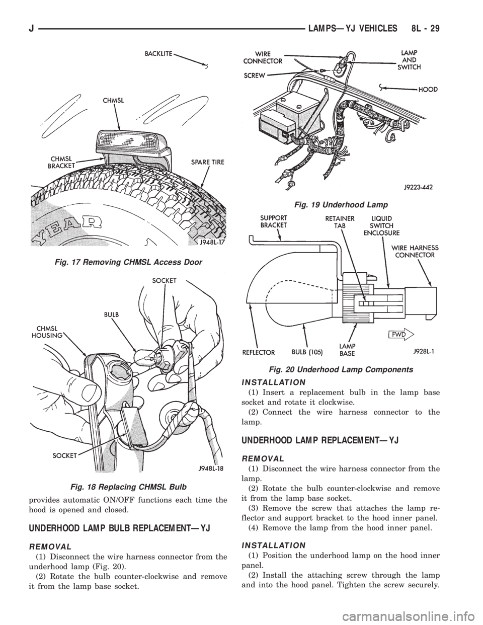
provides automatic ON/OFF functions each time the
hood is opened and closed.
UNDERHOOD LAMP BULB REPLACEMENTÐYJ
REMOVAL
(1) Disconnect the wire harness connector from the
underhood lamp (Fig. 20).
(2) Rotate the bulb counter-clockwise and remove
it from the lamp base socket.
INSTALLATION
(1) Insert a replacement bulb in the lamp base
socket and rotate it clockwise.
(2) Connect the wire harness connector to the
lamp.
UNDERHOOD LAMP REPLACEMENTÐYJ
REMOVAL
(1) Disconnect the wire harness connector from the
lamp.
(2) Rotate the bulb counter-clockwise and remove
it from the lamp base socket.
(3) Remove the screw that attaches the lamp re-
flector and support bracket to the hood inner panel.
(4) Remove the lamp from the hood inner panel.
INSTALLATION
(1) Position the underhood lamp on the hood inner
panel.
(2) Install the attaching screw through the lamp
and into the hood panel. Tighten the screw securely.
Fig. 17 Removing CHMSL Access Door
Fig. 18 Replacing CHMSL Bulb
Fig. 19 Underhood Lamp
Fig. 20 Underhood Lamp Components
JLAMPSÐYJ VEHICLES 8L - 29
Page 490 of 2158

(3) Insert a replacement bulb in the lamp base
socket and rotate it clockwise.
(4) Connect the wire harness connector to the
lamp.
DAYTIME RUNNING LIGHTS (CANADA ONLY)ÐYJ
The Daytime Running Lights (Headlamps) System
is installed on vehicles manufactured for sale in Can-
ada only. The headlamps are illuminated when the
ignition switch is turned to the ON position. The
DRL module receives a vehicle-moving signal from
the vehicle speed sensor. This provides a constant
headlamps-oncondition as long as the vehicle is
moving. The lamps are illuminated at less than 50
percent of normal intensity.
DRL MODULE REPLACEMENTÐYJ
REMOVAL
The daytime running light module is located on the
left fender inner panel below the engine air cleaner
housing.
(1) Remove the engine air cleaner housing for ac-
cess to the DRL module.
(2) Disconnect the wire harness connector from the
module.
(3) Remove the screws that attach the module to
the fender inner panel (Fig. 21).(4) Remove the module from the fender inner
panel.
INSTALLATION
(1) Position the DRL module on the left, fender in-
ner panel.
(2) Install the attaching screws. Tighten the
screws securely.
(3) Connect the wire harness connector to the mod-
ule.
(4) Install the air cleaner housing.
Fig. 21 Daytime Running Lamp Module
8L - 30 LAMPSÐYJ VEHICLESJ
Page 498 of 2158
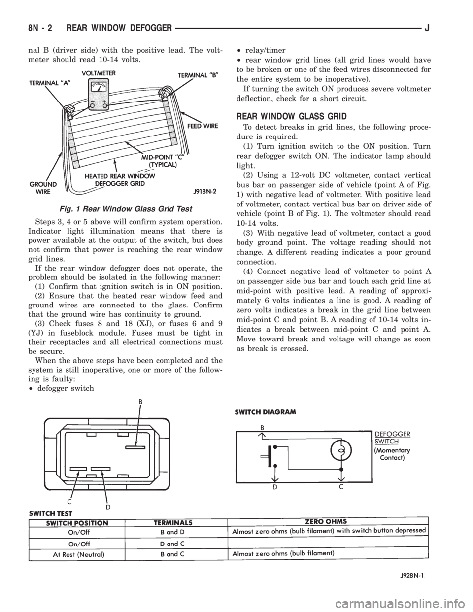
nal B (driver side) with the positive lead. The volt-
meter should read 10-14 volts.
Steps 3, 4 or 5 above will confirm system operation.
Indicator light illumination means that there is
power available at the output of the switch, but does
not confirm that power is reaching the rear window
grid lines.
If the rear window defogger does not operate, the
problem should be isolated in the following manner:
(1) Confirm that ignition switch is in ON position.
(2) Ensure that the heated rear window feed and
ground wires are connected to the glass. Confirm
that the ground wire has continuity to ground.
(3) Check fuses 8 and 18 (XJ), or fuses 6 and 9
(YJ) in fuseblock module. Fuses must be tight in
their receptacles and all electrical connections must
be secure.
When the above steps have been completed and the
system is still inoperative, one or more of the follow-
ing is faulty:
²defogger switch²relay/timer
²rear window grid lines (all grid lines would have
to be broken or one of the feed wires disconnected for
the entire system to be inoperative).
If turning the switch ON produces severe voltmeter
deflection, check for a short circuit.
REAR WINDOW GLASS GRID
To detect breaks in grid lines, the following proce-
dure is required:
(1) Turn ignition switch to the ON position. Turn
rear defogger switch ON. The indicator lamp should
light.
(2) Using a 12-volt DC voltmeter, contact vertical
bus bar on passenger side of vehicle (point A of Fig.
1) with negative lead of voltmeter. With positive lead
of voltmeter, contact vertical bus bar on driver side of
vehicle (point B of Fig. 1). The voltmeter should read
10-14 volts.
(3) With negative lead of voltmeter, contact a good
body ground point. The voltage reading should not
change. A different reading indicates a poor ground
connection.
(4) Connect negative lead of voltmeter to point A
on passenger side bus bar and touch each grid line at
mid-point with positive lead. A reading of approxi-
mately 6 volts indicates a line is good. A reading of
zero volts indicates a break in the grid line between
mid-point C and point B. A reading of 10-14 volts in-
dicates a break between mid-point C and point A.
Move toward break and voltage will change as soon
as break is crossed.
Fig. 1 Rear Window Glass Grid Test
8N - 2 REAR WINDOW DEFOGGERJ
Page 513 of 2158

POWER SEATS
CONTENTS
page page
DIAGNOSIS............................. 2
GENERAL INFORMATION.................. 1SERVICE PROCEDURES................... 3
GENERAL INFORMATION
A six-way driver's side power seat is an available
option on XJ (Cherokee) models. The power seat sys-
tem receives battery feed through fuse 6 in the power
distribution center and circuit breaker 16 in the fuse-
block module at all times.
Following are general descriptions of the major
components in the power seat system. Refer to Group
8W - Wiring Diagrams for complete circuit descrip-
tions and diagrams.
POWER SEAT SWITCH
The power seat can be adjusted in six different
ways using the power seat switch (Fig. 1). The switch
is located on the lower outboard side of the seat
cushion. Refer to the owner's manual for more infor-
mation on power seat switch functions and seat ad-
justing procedures. The individual switches cannot be
repaired. If one switch fails, the entire switch module
must be replaced.
POWER SEAT ADJUSTER/MOTORS
There are three reversible motors that operate the
power seat adjuster. The motors are connected to
worm-drive gearboxes in the adjuster by drive cables.
The front and rear of a seat are operated by differ-
ent motors. They can be raised or lowered indepen-
dently of each other. When the center seat switch is
pushed to the UP or DOWN position, both front and
rear motors operate in unison, moving the entire seat
up or down. The forward-rearward motor is operated
by pushing the center seat switch to the FORWARD
or REARWARD position.
When a switch is actuated, battery feed and a
ground path are applied through the switch contacts
to the motor(s). The motor(s) operate to move the
seat in the selected direction until the switch is re-
leased, or until the travel limit of the power seat ad-juster is reached. When the switch is moved in the
opposite direction, the battery feed and ground path
to the motor(s) are reversed through the switch con-
tacts. This causes the motor to run in the opposite di-
rection.
Each motor contains a self-resetting circuit breaker
to protect it from overload. Consecutive or frequent
resetting must not be allowed to continue or the mo-
tors may be damaged. Make the necessary repairs.
The power seat adjuster and motors can not be re-
paired, and are serviced only as a complete unit. If
any component in this unit should fail, the entire as-
sembly must be replaced.
Fig. 1 Power Seat Switch
JPOWER SEATS 8R - 1
Page 515 of 2158
SERVICE PROCEDURES
POWER SEAT SWITCH REMOVE/INSTALL
(1) Disconnect battery negative cable.
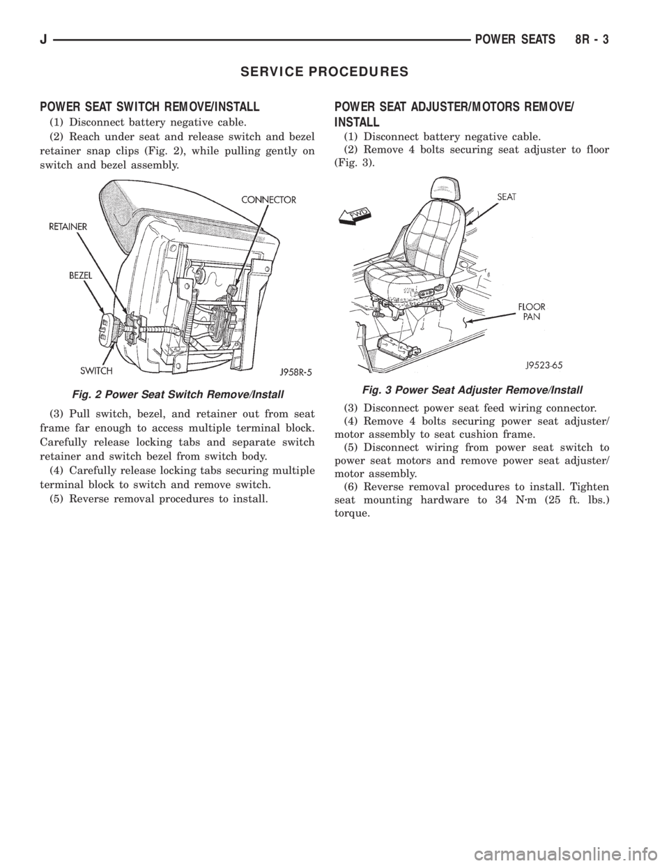
(2) Reach under seat and release switch and bezel
retainer snap clips (Fig. 2), while pulling gently on
switch and bezel assembly.
(3) Pull switch, bezel, and retainer out from seat
frame far enough to access multiple terminal block.
Carefully release locking tabs and separate switch
retainer and switch bezel from switch body.
(4) Carefully release locking tabs securing multiple
terminal block to switch and remove switch.
(5) Reverse removal procedures to install.
POWER SEAT ADJUSTER/MOTORS REMOVE/
INSTALL
(1) Disconnect battery negative cable.
(2) Remove 4 bolts securing seat adjuster to floor
(Fig. 3).
(3) Disconnect power seat feed wiring connector.
(4) Remove 4 bolts securing power seat adjuster/
motor assembly to seat cushion frame.
(5) Disconnect wiring from power seat switch to
power seat motors and remove power seat adjuster/
motor assembly.
(6) Reverse removal procedures to install. Tighten
seat mounting hardware to 34 Nzm (25 ft. lbs.)
torque.
Fig. 2 Power Seat Switch Remove/InstallFig. 3 Power Seat Adjuster Remove/Install
JPOWER SEATS 8R - 3
Page 517 of 2158
POWER WINDOWS
CONTENTS
page page
DIAGNOSIS............................. 1
GENERAL INFORMATION.................. 1SERVICE PROCEDURES................... 7
GENERAL INFORMATION
Power door windows are optional equipment on XJ
(Cherokee) models. The power windows operate only
with the ignition switch in the ON position. This
group covers diagnosis and service of the electrical
components peculiar to the power window system.
For service of mechanical components such as the
regulator, lift plate or window tracks refer to Group
23 - Body Components.
Following are general descriptions of the major
components in the power window system. Refer to
Group 8W - Wiring Diagrams for complete circuit de-
scriptions and diagrams.
POWER WINDOW SWITCH
Both front and rear door windows can be raised or
lowered electrically by operating the four two-way
switches on the driver's door panel. A single two-way
switch on each passenger's door panel operates only
the window on that passenger's door. The switches
cannot be repaired. If faulty, they must be replaced.
POWER WINDOW MOTOR
A permanent magnet reversible motor moves the
window regulator through a cable and drum operat-ing mechanism. A positive and negative battery con-
nection to the two motor terminals will cause the
motor to rotate in one direction. Reversing current
through these same two connections will cause the
motor to rotate in the opposite direction. In addition,
each power window motor is equipped with an inte-
gral automatic re-setting circuit breaker to protect
the motor from overloads. The power window motor
and regulator assembly cannot be repaired. If faulty,
the entire assembly must be replaced.
CIRCUIT BREAKER
An automatic re-setting circuit breaker in the fuse-
block module is used to protect the power window
system circuit. The circuit breaker can protect the
system from a short circuit, and can also protect the
system from an overload condition caused by an ob-
structed or stuck window glass or regulator. The cir-
cuit breaker can not be repaired. If faulty, it must be
replaced.
DIAGNOSIS
It is necessary that the window be free to slide up
and down for the power window system to function
properly. If the window is not free to move up and
down, the motor will overload and trip the circuit
breaker. To determine if the glass is free, disconnect
regulator plate from the glass and slide window up
and down by hand.
An alternate method is to shake the glass in the
door, with the glass positioned between the up and
down stop positions. Check that the glass can be
moved slightly from side to side, front to rear, and up
and down. Then check that window is not boundtight in the tracks. If window is free, proceed with di-
agnosis that follows. If window is not free, refer to
Group 23 - Body Components for service procedures.
CIRCUIT BREAKER
Locate correct circuit breaker in fuseblock module.
Pull out slightly, but be sure that circuit breaker ter-
minals still contact terminals in fuseblock module.
Turn ignition switch to ON position. Connect ground
wire of voltmeter to a good ground. With probe of
voltmeter positive lead, check both terminals of cir-
cuit breaker for battery voltage. If only one terminal
JPOWER WINDOWS 8S - 1
Page 540 of 2158
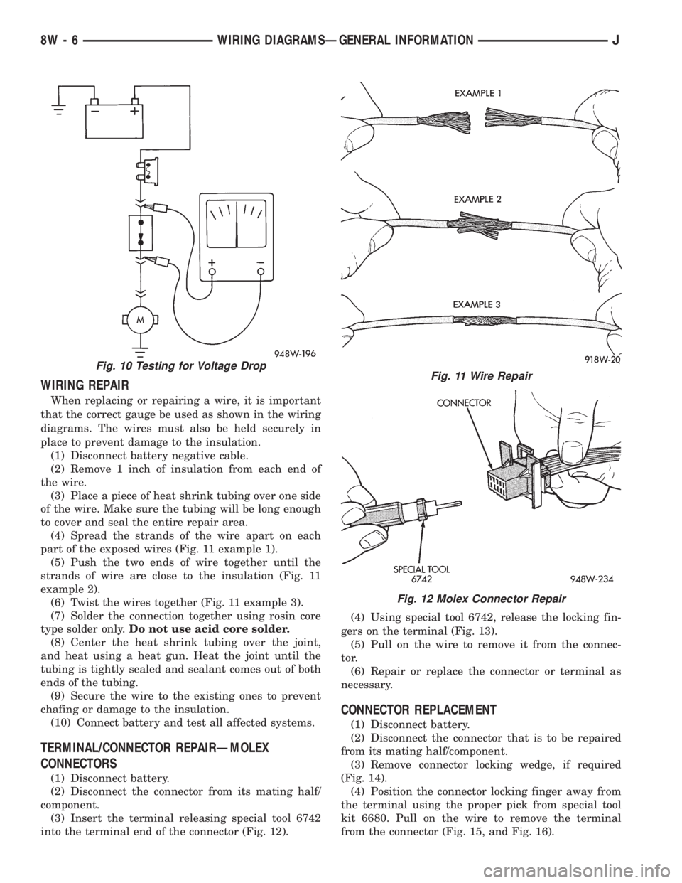
WIRING REPAIR
When replacing or repairing a wire, it is important
that the correct gauge be used as shown in the wiring
diagrams. The wires must also be held securely in
place to prevent damage to the insulation.
(1) Disconnect battery negative cable.
(2) Remove 1 inch of insulation from each end of
the wire.
(3) Place a piece of heat shrink tubing over one side
of the wire. Make sure the tubing will be long enough
to cover and seal the entire repair area.
(4) Spread the strands of the wire apart on each
part of the exposed wires (Fig. 11 example 1).
(5) Push the two ends of wire together until the
strands of wire are close to the insulation (Fig. 11
example 2).
(6) Twist the wires together (Fig. 11 example 3).
(7) Solder the connection together using rosin core
type solder only.Do not use acid core solder.
(8) Center the heat shrink tubing over the joint,
and heat using a heat gun. Heat the joint until the
tubing is tightly sealed and sealant comes out of both
ends of the tubing.
(9) Secure the wire to the existing ones to prevent
chafing or damage to the insulation.
(10) Connect battery and test all affected systems.
TERMINAL/CONNECTOR REPAIRÐMOLEX
CONNECTORS
(1) Disconnect battery.
(2) Disconnect the connector from its mating half/
component.
(3) Insert the terminal releasing special tool 6742
into the terminal end of the connector (Fig. 12).(4) Using special tool 6742, release the locking fin-
gers on the terminal (Fig. 13).
(5) Pull on the wire to remove it from the connec-
tor.
(6) Repair or replace the connector or terminal as
necessary.
CONNECTOR REPLACEMENT
(1) Disconnect battery.
(2) Disconnect the connector that is to be repaired
from its mating half/component.
(3) Remove connector locking wedge, if required
(Fig. 14).
(4) Position the connector locking finger away from
the terminal using the proper pick from special tool
kit 6680. Pull on the wire to remove the terminal
from the connector (Fig. 15, and Fig. 16).
Fig. 10 Testing for Voltage DropFig. 11 Wire Repair
Fig. 12 Molex Connector Repair
8W - 6 WIRING DIAGRAMSÐGENERAL INFORMATIONJ
Page 1284 of 2158
ENGINE DIAGNOSIS
Engine diagnosis is helpful in determining the
causes of malfunctions not detected and remedied by
routine tune-ups.
These malfunctions may be classified as either per-
formance (e.g., engine idles rough and stalls) or me-
chanical (e.g., a strange noise).
Refer to the Service DiagnosisÐPerformance chart
and the Service DiagnosisÐMechanical chart for pos-
sible causes and corrections of malfunctions. Refer to
Group 14, Fuel System for the fuel system diagnosis.
GENERAL INFORMATION
Additional tests and diagnostic procedures may be
necessary for specific engine malfunctions that can
not be isolated with the Service Diagnosis charts. In-
formation concerning additional tests and diagnosis
is provided within the following diagnosis:
²Cylinder Compression Pressure Test.
²Cylinder Combustion Pressure Leakage Test.
²Engine Cylinder Head Gasket Failure Diagnosis.
²Intake Manifold Leakage Diagnosis.
INTAKE MANIFOLD LEAKAGE DIAGNOSIS
An intake manifold air leak is characterized by
lower than normal manifold vacuum. Also, one or
more cylinders may not be functioning.
WARNING: USE EXTREME CAUTION WHEN THE
ENGINE IS OPERATING. DO NOT STAND IN A DI-
RECT LINE WITH THE FAN. DO NOT PUT YOUR
HANDS NEAR THE PULLEYS, BELTS OR THE FAN.
DO NOT WEAR LOOSE CLOTHING.
METHOD 1
(1) Start the engine.
(2) Spray a small stream of water at the suspected
leak area.
(3) If a change in RPM'S, the area of the suspected
leak has been found.
(4) Repair as required.
CYLINDER COMPRESSION PRESSURE TEST
The results of a cylinder compression pressure test
can be utilized to diagnose several engine malfunc-
tions.
Ensure the battery is completely charged and the
engine starter motor is in good operating condition.
Otherwise the indicated compression pressures may
not be valid for diagnosis purposes.
(1) Clean the spark plug recesses with compressed
air.
(2) Remove the spark plugs.
(3) Secure the throttle in the wide-open position.
(4) Disconnect the ignition coil.(5) Insert a compression pressure gauge and rotate
the engine with the engine starter motor for three
revolutions.
(6) Record the compression pressure on the 3rd
revolution. Continue the test for the remaining cylin-
ders.
Refer to Engine Specifications for the correct en-
gine compression pressures.
ENGINE CYLINDER HEAD GASKET FAILURE
DIAGNOSIS
A leaking engine cylinder head gasket usually re-
sults in loss of power, loss of coolant and engine mis-
firing.
An engine cylinder head gasket leak can be located
between adjacent cylinders or between a cylinder and
the adjacent water jacket.
²An engine cylinder head gasket leaking between
adjacent cylinders is indicated by a loss of power
and/or engine misfire.
²An engine cylinder head gasket leaking between a
cylinder and an adjacent water jacket is indicated by
coolant foaming or overheating and loss of coolant.
CYLINDER-TO-CYLINDER LEAKAGE TEST
To determine if an engine cylinder head gasket is
leaking between adjacent cylinders; follow the proce-
dures outlined in Cylinder Compression Pressure
Test. An engine cylinder head gasket leaking between
adjacent cylinders will result in approximately a 50-
70% reduction in compression pressure.
CYLINDER-TO-WATER JACKET LEAKAGE
TEST
WARNING: USE EXTREME CAUTION WHEN THE
ENGINE IS OPERATING. DO NOT STAND IN A DI-
RECT LINE WITH THE FAN. DO NOT PUT YOUR
HANDS NEAR THE PULLEYS, BELTS OR THE FAN.
DO NOT WEAR LOOSE CLOTHING.
Remove the radiator cap.
Start the engine and allow it to warm up until the
engine thermostat opens.
If a large combustion/compression pressure leak ex-
ists, bubbles will be visible in the coolant.
If bubbles are not visible, install a radiator pres-
sure tester and pressurize the coolant system.
If a cylinder is leaking combustion pressure into
the water jacket, the tester pointer will pulsate with
every combustion stroke of the cylinder.
JENGINES 9 - 5