1995 JEEP YJ ECU
[x] Cancel search: ECUPage 1416 of 2158
(2) Remove the fuel filler cap. Using an approved por-
table gasoline siphon/storage tank, drain fuel tank.
(3) Raise and support vehicle.
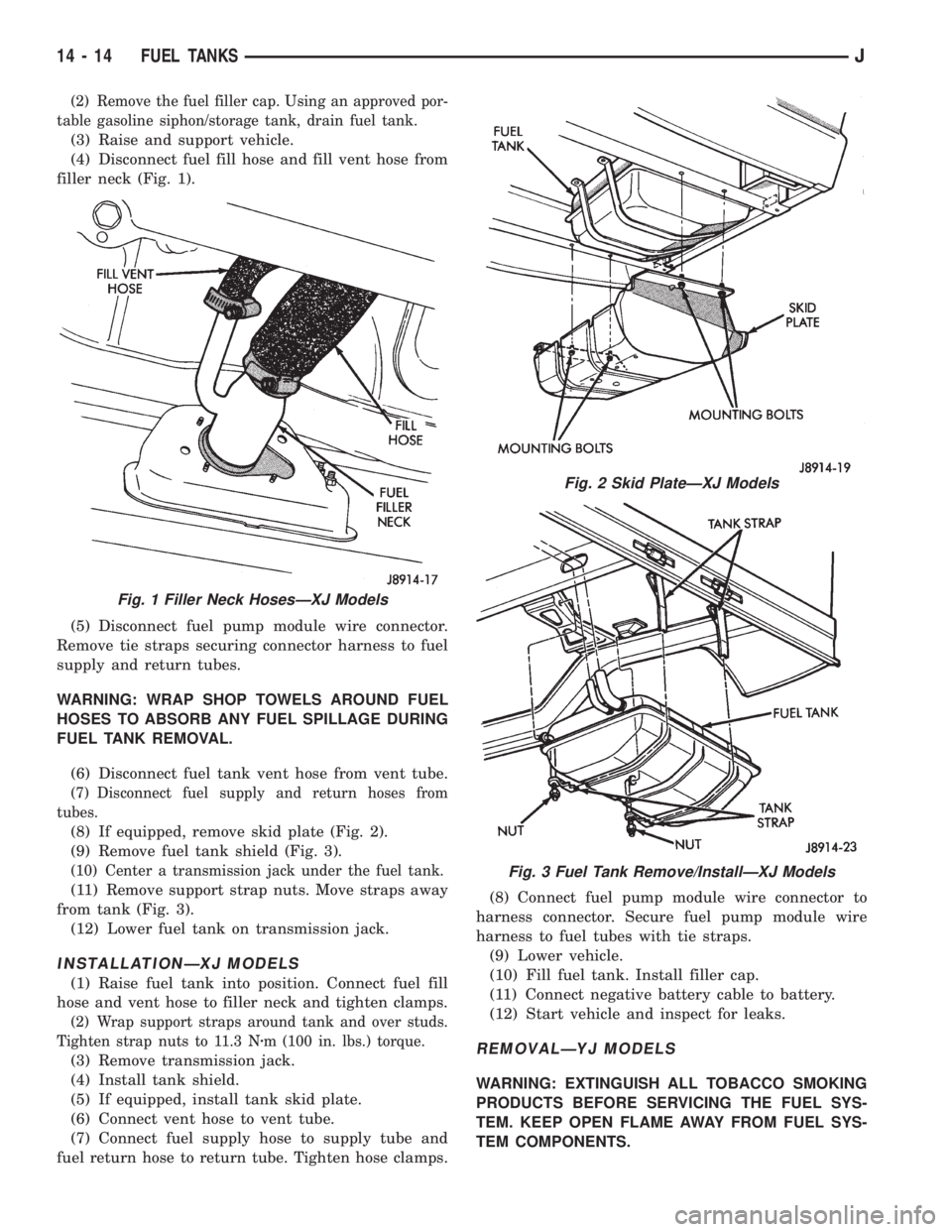
(4) Disconnect fuel fill hose and fill vent hose from
filler neck (Fig. 1).
(5) Disconnect fuel pump module wire connector.
Remove tie straps securing connector harness to fuel
supply and return tubes.
WARNING: WRAP SHOP TOWELS AROUND FUEL
HOSES TO ABSORB ANY FUEL SPILLAGE DURING
FUEL TANK REMOVAL.
(6) Disconnect fuel tank vent hose from vent tube.
(7) Disconnect fuel supply and return hoses from
tubes.
(8) If equipped, remove skid plate (Fig. 2).
(9) Remove fuel tank shield (Fig. 3).
(10) Center a transmission jack under the fuel tank.
(11) Remove support strap nuts. Move straps away
from tank (Fig. 3).
(12) Lower fuel tank on transmission jack.
INSTALLATIONÐXJ MODELS
(1) Raise fuel tank into position. Connect fuel fill
hose and vent hose to filler neck and tighten clamps.
(2) Wrap support straps around tank and over studs.
Tighten strap nuts to 11.3 Nzm (100 in. lbs.) torque.
(3) Remove transmission jack.
(4) Install tank shield.
(5) If equipped, install tank skid plate.
(6) Connect vent hose to vent tube.
(7) Connect fuel supply hose to supply tube and
fuel return hose to return tube. Tighten hose clamps.(8) Connect fuel pump module wire connector to
harness connector. Secure fuel pump module wire
harness to fuel tubes with tie straps.
(9) Lower vehicle.
(10) Fill fuel tank. Install filler cap.
(11) Connect negative battery cable to battery.
(12) Start vehicle and inspect for leaks.REMOVALÐYJ MODELS
WARNING: EXTINGUISH ALL TOBACCO SMOKING
PRODUCTS BEFORE SERVICING THE FUEL SYS-
TEM. KEEP OPEN FLAME AWAY FROM FUEL SYS-
TEM COMPONENTS.
Fig. 1 Filler Neck HosesÐXJ Models
Fig. 2 Skid PlateÐXJ Models
Fig. 3 Fuel Tank Remove/InstallÐXJ Models
14 - 14 FUEL TANKSJ
Page 1417 of 2158
(1) Disconnect negative battery cable.
(2) Remove the fuel filler cap. Using an approved
portable gasoline siphon/storage tank, drain fuel
tank.
(3) Raise and support vehicle.
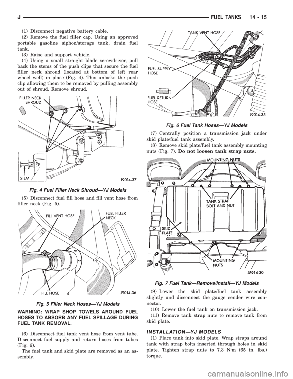
(4) Using a small straight blade screwdriver, pull
back the stems of the push clips that secure the fuel
filler neck shroud (located at bottom of left rear
wheel well) in place (Fig. 4). This unlocks the push
clip allowing them to be removed by pulling assembly
out of shroud. Remove shroud.
(5) Disconnect fuel fill hose and fill vent hose from
filler neck (Fig. 5).
WARNING: WRAP SHOP TOWELS AROUND FUEL
HOSES TO ABSORB ANY FUEL SPILLAGE DURING
FUEL TANK REMOVAL.
(6) Disconnect fuel tank vent hose from vent tube.
Disconnect fuel supply and return hoses from tubes
(Fig. 6).
The fuel tank and skid plate are removed as an as-
sembly.(7) Centrally position a transmission jack under
skid plate/fuel tank assembly.
(8) Remove skid plate/fuel tank assembly mounting
nuts (Fig. 7).Do not loosen tank strap nuts.
(9) Lower the skid plate/fuel tank assembly
slightly and disconnect the gauge sender wire con-
nector.
(10) Lower the fuel tank on transmission jack.
(11) Remove tank strap nuts to remove tank from
skid plate.
INSTALLATIONÐYJ MODELS
(1) Place tank into skid plate. Wrap straps around
tank with strap bolts inserted through holes in skid
plate. Tighten strap nuts to 7.3 Nzm (65 in. lbs.)
torque.
Fig. 4 Fuel Filler Neck ShroudÐYJ Models
Fig. 5 Filler Neck HosesÐYJ Models
Fig. 6 Fuel Tank HosesÐYJ Models
Fig. 7 Fuel TankÐRemove/InstallÐYJ Models
JFUEL TANKS 14 - 15
Page 1460 of 2158
MULTI-PORT FUEL INJECTION (MFI)ÐCOMPONENT REMOVAL/INSTALLATION
INDEX
page page
Accelerator Pedal and Throttle Cable........... 58
Air Cleaner Element....................... 59
Air Cleaner Housing....................... 58
Air Conditioning (A/C) Clutch Relay............ 58
Automatic Shutdown (ASD) Relay............. 59
Brake Switch............................ 59
Camshaft Position Sensor................... 60
Crankshaft Position Sensor.................. 60
Engine Coolant Temperature Sensor........... 60
Fuel Filter............................... 60
Fuel Injector............................. 60
Fuel Pressure Regulator.................... 61
Fuel Pump Module........................ 61
Fuel Pump Relay......................... 61
Fuel Rail Assembly........................ 62
Fuel System Pressure Release Procedure....... 62
Fuel Tank Pressure Relief/Rollover Valve........ 62Fuel Tanks.............................. 62
Fuel Tubes/Lines/Hoses and Clamps........... 62
Idle Air Control (IAC) Motor.................. 62
Ignition Coil............................. 62
Intake Manifold........................... 63
Intake Manifold Air Temperature Sensor......... 60
Manifold Absolute Pressure (Map) Sensor....... 63
Oxygen (O2S) Sensor...................... 63
Park Neutral Switch....................... 63
Power Steering Pressure SwitchÐ2.5L
Engine Only............................ 63
Powertrain Control Module (PCM)............. 64
Quick-Connect Fittings..................... 64
Throttle Body............................ 64
Throttle Position Sensor (TPS)............... 65
Torque Converter Clutch Relay............... 65
Vehicle Speed Sensor...................... 66
ACCELERATOR PEDAL AND THROTTLE CABLE
Refer to the Accelerator Pedal and Throttle Cable
section of this group for removal/installation proce-
dures.
AIR CONDITIONING (A/C) CLUTCH RELAY
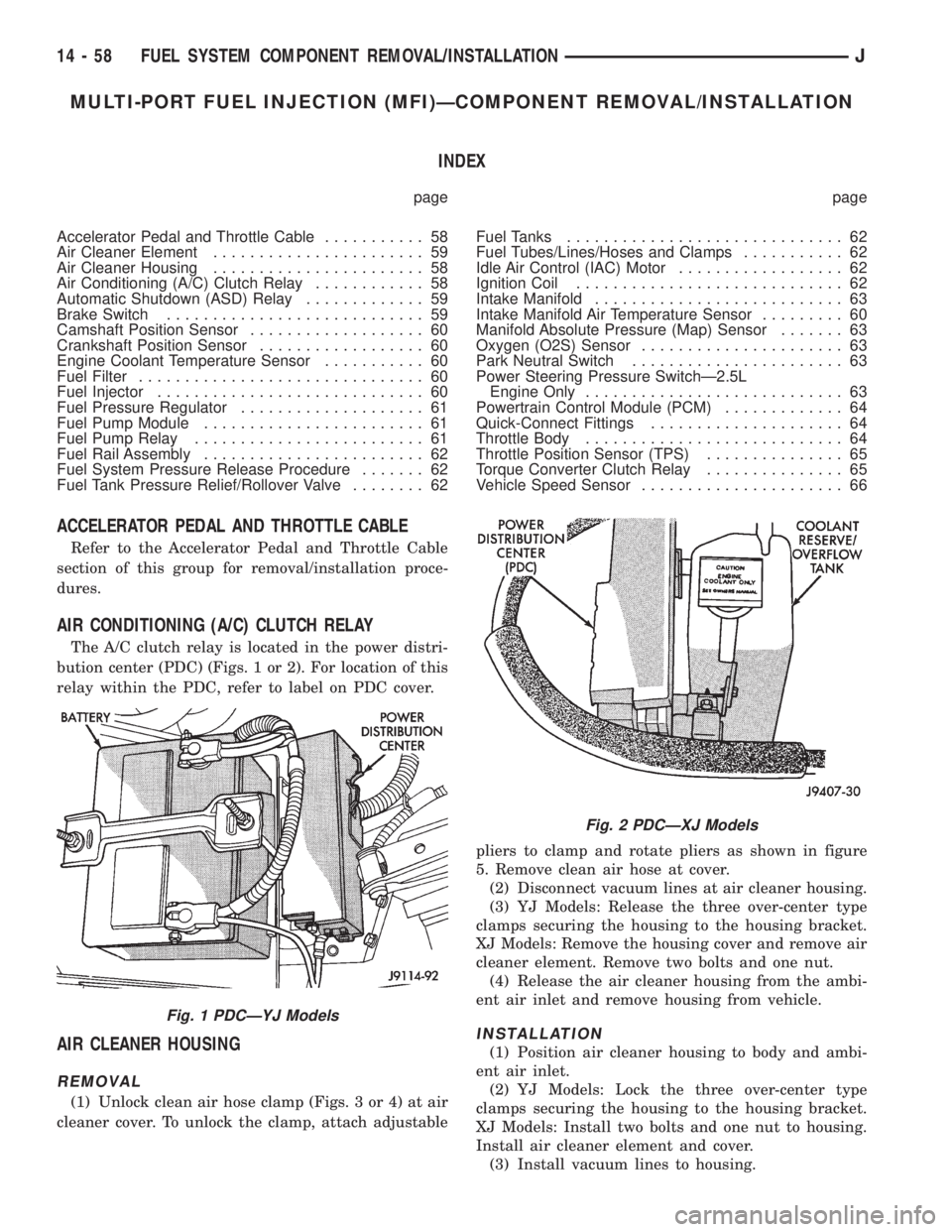
The A/C clutch relay is located in the power distri-
bution center (PDC) (Figs. 1 or 2). For location of this
relay within the PDC, refer to label on PDC cover.
AIR CLEANER HOUSING
REMOVAL
(1) Unlock clean air hose clamp (Figs. 3 or 4) at air
cleaner cover. To unlock the clamp, attach adjustablepliers to clamp and rotate pliers as shown in figure
5. Remove clean air hose at cover.
(2) Disconnect vacuum lines at air cleaner housing.
(3) YJ Models: Release the three over-center type
clamps securing the housing to the housing bracket.
XJ Models: Remove the housing cover and remove air
cleaner element. Remove two bolts and one nut.
(4) Release the air cleaner housing from the ambi-
ent air inlet and remove housing from vehicle.
INSTALLATION
(1) Position air cleaner housing to body and ambi-
ent air inlet.
(2) YJ Models: Lock the three over-center type
clamps securing the housing to the housing bracket.
XJ Models: Install two bolts and one nut to housing.
Install air cleaner element and cover.
(3) Install vacuum lines to housing.
Fig. 1 PDCÐYJ Models
Fig. 2 PDCÐXJ Models
14 - 58 FUEL SYSTEM COMPONENT REMOVAL/INSTALLATIONJ
Page 1465 of 2158
INTAKE MANIFOLD
Refer to Group 11, Exhaust System and Intake
Manifold for removal/installation procedures.
MANIFOLD ABSOLUTE PRESSURE (MAP) SENSOR
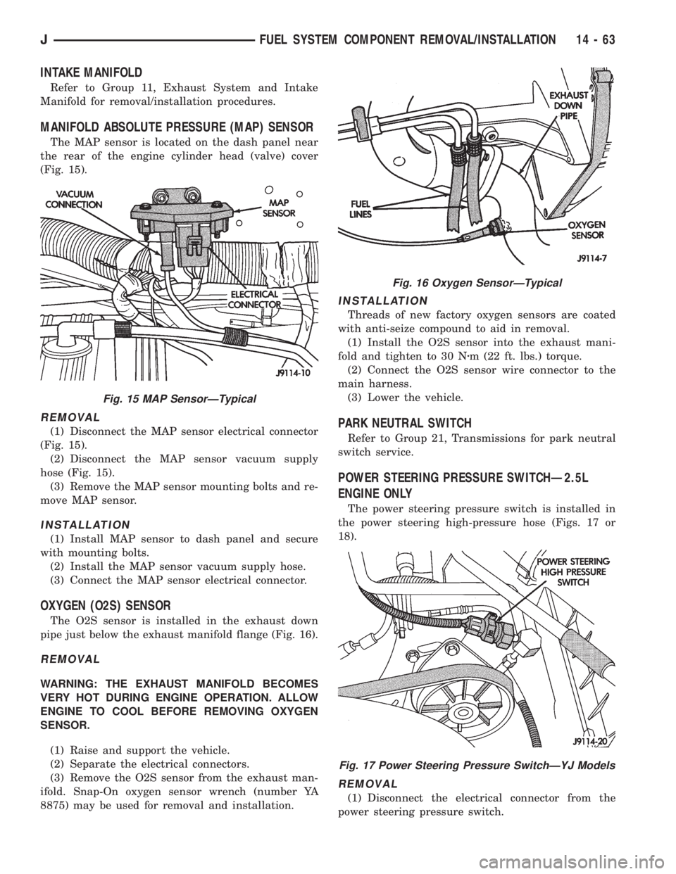
The MAP sensor is located on the dash panel near
the rear of the engine cylinder head (valve) cover
(Fig. 15).
REMOVAL
(1) Disconnect the MAP sensor electrical connector
(Fig. 15).
(2) Disconnect the MAP sensor vacuum supply
hose (Fig. 15).
(3) Remove the MAP sensor mounting bolts and re-
move MAP sensor.
INSTALLATION
(1) Install MAP sensor to dash panel and secure
with mounting bolts.
(2) Install the MAP sensor vacuum supply hose.
(3) Connect the MAP sensor electrical connector.
OXYGEN (O2S) SENSOR
The O2S sensor is installed in the exhaust down
pipe just below the exhaust manifold flange (Fig. 16).
REMOVAL
WARNING: THE EXHAUST MANIFOLD BECOMES
VERY HOT DURING ENGINE OPERATION. ALLOW
ENGINE TO COOL BEFORE REMOVING OXYGEN
SENSOR.
(1) Raise and support the vehicle.
(2) Separate the electrical connectors.
(3) Remove the O2S sensor from the exhaust man-
ifold. Snap-On oxygen sensor wrench (number YA
8875) may be used for removal and installation.
INSTALLATION
Threads of new factory oxygen sensors are coated
with anti-seize compound to aid in removal.
(1) Install the O2S sensor into the exhaust mani-
fold and tighten to 30 Nzm (22 ft. lbs.) torque.
(2) Connect the O2S sensor wire connector to the
main harness.
(3) Lower the vehicle.
PARK NEUTRAL SWITCH
Refer to Group 21, Transmissions for park neutral
switch service.
POWER STEERING PRESSURE SWITCHÐ2.5L
ENGINE ONLY
The power steering pressure switch is installed in
the power steering high-pressure hose (Figs. 17 or
18).
REMOVAL
(1) Disconnect the electrical connector from the
power steering pressure switch.
Fig. 15 MAP SensorÐTypical
Fig. 16 Oxygen SensorÐTypical
Fig. 17 Power Steering Pressure SwitchÐYJ Models
JFUEL SYSTEM COMPONENT REMOVAL/INSTALLATION 14 - 63
Page 1514 of 2158
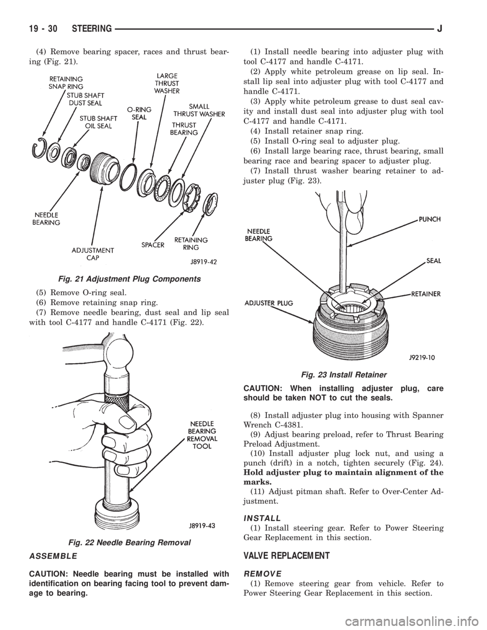
(4) Remove bearing spacer, races and thrust bear-
ing (Fig. 21).
(5) Remove O-ring seal.
(6) Remove retaining snap ring.
(7) Remove needle bearing, dust seal and lip seal
with tool C-4177 and handle C-4171 (Fig. 22).
ASSEMBLE
CAUTION: Needle bearing must be installed with
identification on bearing facing tool to prevent dam-
age to bearing.(1) Install needle bearing into adjuster plug with
tool C-4177 and handle C-4171.
(2) Apply white petroleum grease on lip seal. In-
stall lip seal into adjuster plug with tool C-4177 and
handle C-4171.
(3) Apply white petroleum grease to dust seal cav-
ity and install dust seal into adjuster plug with tool
C-4177 and handle C-4171.
(4) Install retainer snap ring.
(5) Install O-ring seal to adjuster plug.
(6) Install large bearing race, thrust bearing, small
bearing race and bearing spacer to adjuster plug.
(7) Install thrust washer bearing retainer to ad-
juster plug (Fig. 23).
CAUTION: When installing adjuster plug, care
should be taken NOT to cut the seals.
(8) Install adjuster plug into housing with Spanner
Wrench C-4381.
(9) Adjust bearing preload, refer to Thrust Bearing
Preload Adjustment.
(10) Install adjuster plug lock nut, and using a
punch (drift) in a notch, tighten securely (Fig. 24).
Hold adjuster plug to maintain alignment of the
marks.
(11) Adjust pitman shaft. Refer to Over-Center Ad-
justment.
INSTALL
(1) Install steering gear. Refer to Power Steering
Gear Replacement in this section.
VALVE REPLACEMENT
REMOVE
(1) Remove steering gear from vehicle. Refer to
Power Steering Gear Replacement in this section.
Fig. 21 Adjustment Plug Components
Fig. 22 Needle Bearing Removal
Fig. 23 Install Retainer
19 - 30 STEERINGJ
Page 1540 of 2158
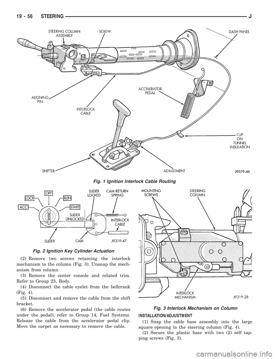
(2) Remove two screws retaining the interlock
mechanism to the column (Fig. 3). Unsnap the mech-
anism from column.
(3) Remove the center console and related trim.
Refer to Group 23, Body.
(4) Disconnect the cable eyelet from the bellcrank
(Fig. 4).
(5) Disconnect and remove the cable from the shift
bracket.
(6) Remove the accelerator pedal (the cable routes
under the pedal), refer to Group 14, Fuel Systems.
Release the cable from the accelerator pedal clip.
Move the carpet as necessary to remove the cable.INSTALLATION/ADJUSTMENT
(1) Snap the cable base assembly into the large
square opening in the steering column (Fig. 4).
(2) Secure the plastic base with two (2) self tap-
ping screws (Fig. 3).
Fig. 1 Ignition Interlock Cable Routing
Fig. 2 Ignition Key Cylinder Actuation
Fig. 3 Interlock Mechanism on Column
19 - 56 STEERINGJ
Page 1549 of 2158
(6) Position the turn signal switch and wire har-
ness in the cylinder housing. Fold the wires against
the connector. Route the connector down through the
steering column jacket.
(7) Install the windshield wiper wire harness and
switch. Route the wire harness down through steer-
ing column jacket.
(8) Align the turn signal switch in the housing and
secure the switch with the attaching screws. Tighten
the screws to 4 Nzm (35 in. lbs.) torque.
(9) Install the dimmer switch actuator arm.
Tighten the attaching screws to 4 Nzm (35 in. lbs.)
torque.
(10) If equipped, install the cruise control wire har-
ness. Install the turn signal stalk by pushing it
straight into the column.
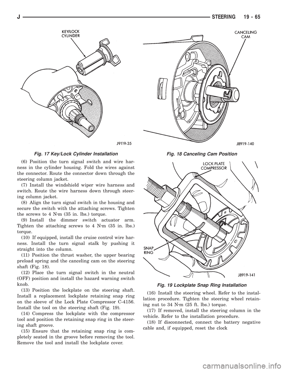
(11) Position the thrust washer, the upper bearing
preload spring and the canceling cam on the steering
shaft (Fig. 18).
(12) Place the turn signal switch in the neutral
(OFF) position and install the hazard warning switch
knob.
(13) Position the lockplate on the steering shaft.
Install a replacement lockplate retaining snap ring
on the sleeve of the Lock Plate Compressor C-4156.
Install the tool on the steering shaft (Fig. 19).
(14) Compress the lockplate with the compressor
tool and position the retaining snap ring in the steer-
ing shaft groove.
(15) Ensure that the retaining snap ring is com-
pletely seated in the groove before removing the tool.
Remove the tool and install the lockplate cover.(16) Install the steering wheel. Refer to the instal-
lation procedure. Tighten the steering wheel retain-
ing nut to 34 Nzm (25 ft. lbs.) torque.
(17) If removed, install the steering column in the
vehicle. Refer to the installation procedure.
(18) If disconnected, connect the battery negative
cable and, if equipped, reset the clock
Fig. 17 Key/Lock Cylinder InstallationFig. 18 Canceling Cam Position
Fig. 19 Lockplate Snap Ring Installation
JSTEERING 19 - 65
Page 1566 of 2158
(7) Disconnect transfer case shift linkage at trans-
fer case.
(8) Disconnect vehicle speed sensor wires and
transfer case vent hose.
(9) Remove slave cylinder from clutch housing.
(10) Disconnect transmission shift lever as follows:
(a) Lower transmission-transfer case assembly
approximately 7-8 cm (3 in.) for access to shift le-
ver.
(b) Reach up and around transmission case and
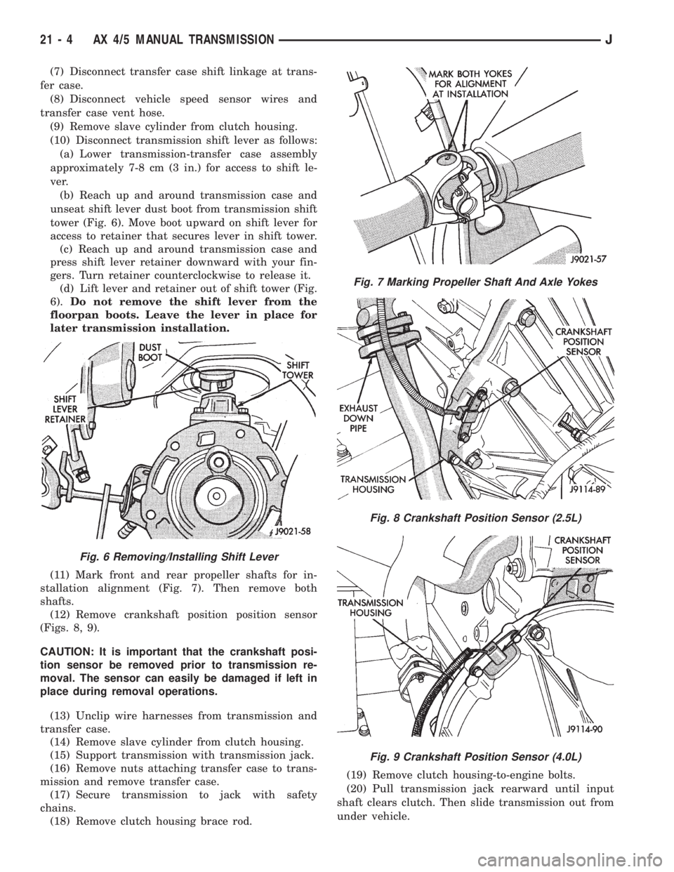
unseat shift lever dust boot from transmission shift
tower (Fig. 6). Move boot upward on shift lever for
access to retainer that secures lever in shift tower.
(c) Reach up and around transmission case and
press shift lever retainer downward with your fin-
gers. Turn retainer counterclockwise to release it.
(d) Lift lever and retainer out of shift tower (Fig.
6).Do not remove the shift lever from the
floorpan boots. Leave the lever in place for
later transmission installation.
(11) Mark front and rear propeller shafts for in-
stallation alignment (Fig. 7). Then remove both
shafts.
(12) Remove crankshaft position position sensor
(Figs. 8, 9).
CAUTION: It is important that the crankshaft posi-
tion sensor be removed prior to transmission re-
moval. The sensor can easily be damaged if left in
place during removal operations.
(13) Unclip wire harnesses from transmission and
transfer case.
(14) Remove slave cylinder from clutch housing.
(15) Support transmission with transmission jack.
(16) Remove nuts attaching transfer case to trans-
mission and remove transfer case.
(17) Secure transmission to jack with safety
chains.
(18) Remove clutch housing brace rod.(19) Remove clutch housing-to-engine bolts.
(20) Pull transmission jack rearward until input
shaft clears clutch. Then slide transmission out from
under vehicle.
Fig. 6 Removing/Installing Shift Lever
Fig. 7 Marking Propeller Shaft And Axle Yokes
Fig. 8 Crankshaft Position Sensor (2.5L)
Fig. 9 Crankshaft Position Sensor (4.0L)
21 - 4 AX 4/5 MANUAL TRANSMISSIONJ