1995 JEEP XJ engine
[x] Cancel search: enginePage 241 of 2158
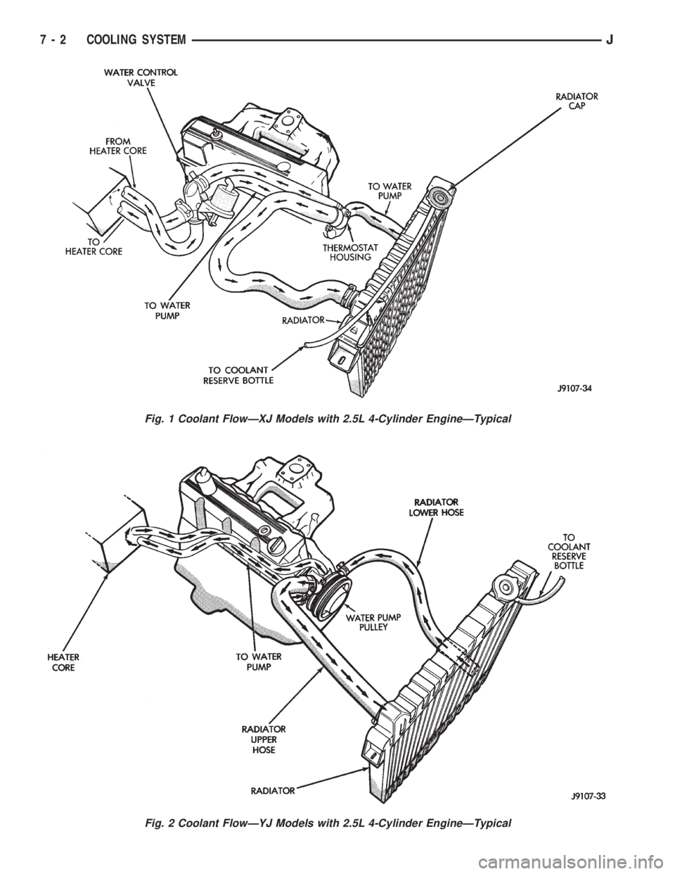
Fig. 1 Coolant FlowÐXJ Models with 2.5L 4-Cylinder EngineÐTypical
Fig. 2 Coolant FlowÐYJ Models with 2.5L 4-Cylinder EngineÐTypical
7 - 2 COOLING SYSTEMJ
Page 242 of 2158
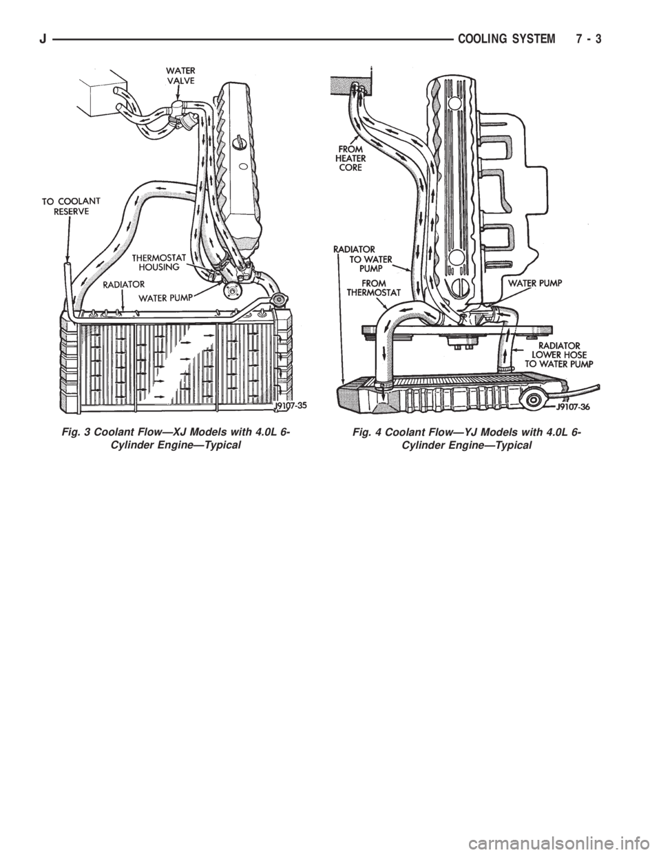
Fig. 3 Coolant FlowÐXJ Models with 4.0L 6-
Cylinder EngineÐTypicalFig. 4 Coolant FlowÐYJ Models with 4.0L 6-
Cylinder EngineÐTypical
JCOOLING SYSTEM 7 - 3
Page 243 of 2158
DIAGNOSIS
INDEX
page page
DRB Scan Tool............................ 5
On-Board Diagnostics (OBD).................. 4Preliminary Checks......................... 5
ON-BOARD DIAGNOSTICS (OBD)
FOR CERTAIN COOLING SYSTEM
COMPONENTS
The powertrain control module (PCM) has been
programmed to monitor the certain following cooling
system components:
²If the engine has remained cool for too long a pe-
riod, such as with a stuck open thermostat, a Diag-
nostic Trouble Code (DTC) number 17 can be
observed at the malfunction indicator lamp. This
lamp is displayed on the instrument panel as the
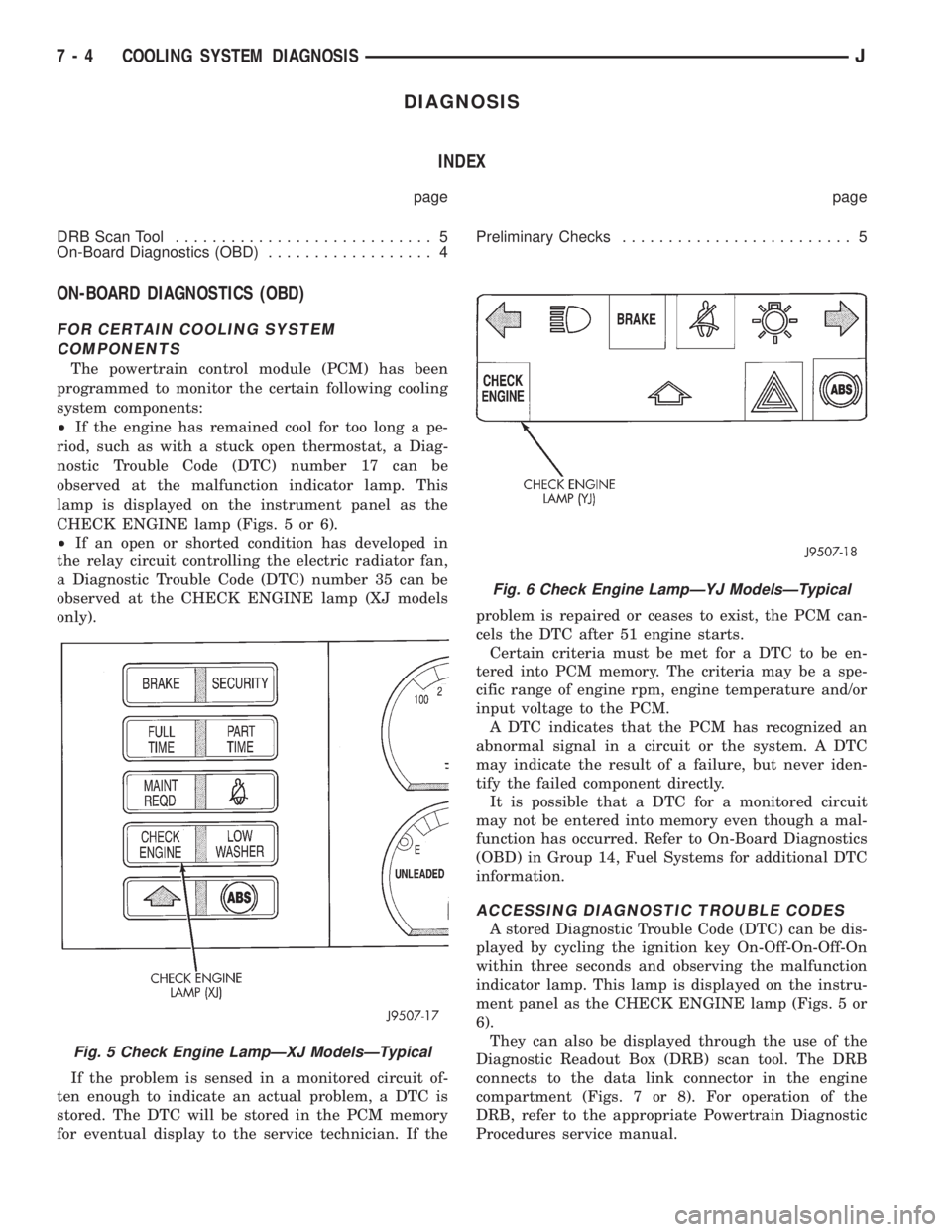
CHECK ENGINE lamp (Figs. 5 or 6).
²If an open or shorted condition has developed in
the relay circuit controlling the electric radiator fan,
a Diagnostic Trouble Code (DTC) number 35 can be
observed at the CHECK ENGINE lamp (XJ models
only).
If the problem is sensed in a monitored circuit of-
ten enough to indicate an actual problem, a DTC is
stored. The DTC will be stored in the PCM memory
for eventual display to the service technician. If theproblem is repaired or ceases to exist, the PCM can-
cels the DTC after 51 engine starts.
Certain criteria must be met for a DTC to be en-
tered into PCM memory. The criteria may be a spe-
cific range of engine rpm, engine temperature and/or
input voltage to the PCM.
A DTC indicates that the PCM has recognized an
abnormal signal in a circuit or the system. A DTC
may indicate the result of a failure, but never iden-
tify the failed component directly.
It is possible that a DTC for a monitored circuit
may not be entered into memory even though a mal-
function has occurred. Refer to On-Board Diagnostics
(OBD) in Group 14, Fuel Systems for additional DTC
information.
ACCESSING DIAGNOSTIC TROUBLE CODES
A stored Diagnostic Trouble Code (DTC) can be dis-
played by cycling the ignition key On-Off-On-Off-On
within three seconds and observing the malfunction
indicator lamp. This lamp is displayed on the instru-
ment panel as the CHECK ENGINE lamp (Figs. 5 or
6).
They can also be displayed through the use of the
Diagnostic Readout Box (DRB) scan tool. The DRB
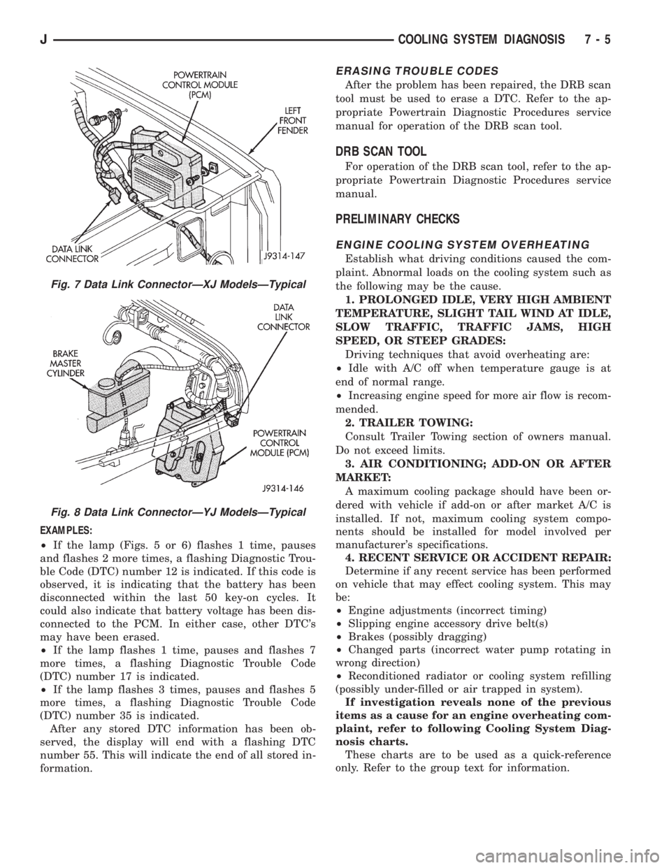
connects to the data link connector in the engine
compartment (Figs. 7 or 8). For operation of the
DRB, refer to the appropriate Powertrain Diagnostic
Procedures service manual.
Fig. 5 Check Engine LampÐXJ ModelsÐTypical
Fig. 6 Check Engine LampÐYJ ModelsÐTypical
7 - 4 COOLING SYSTEM DIAGNOSISJ
Page 244 of 2158
EXAMPLES:
²If the lamp (Figs. 5 or 6) flashes 1 time, pauses
and flashes 2 more times, a flashing Diagnostic Trou-
ble Code (DTC) number 12 is indicated. If this code is
observed, it is indicating that the battery has been
disconnected within the last 50 key-on cycles. It
could also indicate that battery voltage has been dis-
connected to the PCM. In either case, other DTC's
may have been erased.
²If the lamp flashes 1 time, pauses and flashes 7
more times, a flashing Diagnostic Trouble Code
(DTC) number 17 is indicated.
²If the lamp flashes 3 times, pauses and flashes 5
more times, a flashing Diagnostic Trouble Code
(DTC) number 35 is indicated.
After any stored DTC information has been ob-
served, the display will end with a flashing DTC
number 55. This will indicate the end of all stored in-
formation.
ERASING TROUBLE CODES
After the problem has been repaired, the DRB scan
tool must be used to erase a DTC. Refer to the ap-
propriate Powertrain Diagnostic Procedures service
manual for operation of the DRB scan tool.
DRB SCAN TOOL
For operation of the DRB scan tool, refer to the ap-
propriate Powertrain Diagnostic Procedures service
manual.
PRELIMINARY CHECKS
ENGINE COOLING SYSTEM OVERHEATING
Establish what driving conditions caused the com-
plaint. Abnormal loads on the cooling system such as
the following may be the cause.
1. PROLONGED IDLE, VERY HIGH AMBIENT
TEMPERATURE, SLIGHT TAIL WIND AT IDLE,
SLOW TRAFFIC, TRAFFIC JAMS, HIGH
SPEED, OR STEEP GRADES:
Driving techniques that avoid overheating are:
²Idle with A/C off when temperature gauge is at
end of normal range.
²Increasing engine speed for more air flow is recom-
mended.
2. TRAILER TOWING:
Consult Trailer Towing section of owners manual.
Do not exceed limits.
3. AIR CONDITIONING; ADD-ON OR AFTER
MARKET:
A maximum cooling package should have been or-
dered with vehicle if add-on or after market A/C is
installed. If not, maximum cooling system compo-
nents should be installed for model involved per
manufacturer's specifications.
4. RECENT SERVICE OR ACCIDENT REPAIR:
Determine if any recent service has been performed
on vehicle that may effect cooling system. This may
be:
²Engine adjustments (incorrect timing)
²Slipping engine accessory drive belt(s)
²Brakes (possibly dragging)
²Changed parts (incorrect water pump rotating in
wrong direction)
²Reconditioned radiator or cooling system refilling
(possibly under-filled or air trapped in system).
If investigation reveals none of the previous
items as a cause for an engine overheating com-
plaint, refer to following Cooling System Diag-
nosis charts.
These charts are to be used as a quick-reference
only. Refer to the group text for information.
Fig. 7 Data Link ConnectorÐXJ ModelsÐTypical
Fig. 8 Data Link ConnectorÐYJ ModelsÐTypical
JCOOLING SYSTEM DIAGNOSIS 7 - 5
Page 252 of 2158
SERVICE PROCEDURES
INDEX
page page
Auxiliary Electric Cooling FanÐXJ Models with 4.0L
6-Cylinder Engine....................... 35
Coolant................................. 20
Coolant Reserve/Overflow System............. 24
Cooling System Cleaning/Reverse Flushing...... 22
Cooling System Fans...................... 32
Cooling System Hoses..................... 32
Draining Cooling System.................... 21
Radiator Pressure Cap..................... 25
Radiators............................... 26Refilling Cooling System.................... 21
Testing Cooling System for Leaks............. 22
Thermostat.............................. 17
Transmission Oil Coolers.................... 36
Viscous Fan Drive......................... 34
Water Pump Tests......................... 13
Water PumpsÐGeneral Information............ 13
Water PumpsÐRemoval/Installation........... 14
WATER PUMPSÐGENERAL INFORMATION
A centrifugal water pump circulates coolant
through the water jackets, passages, intake manifold,
radiator core, cooling system hoses and heater core.
The pump is driven from the engine crankshaft by a
drive belt on all engines.
The water pump impeller is pressed onto the rear
of a shaft that rotates in bearings pressed into the
housing. The housing has a small hole to allow seep-
age to escape. The water pump seals are lubricated
by the antifreeze in the coolant mixture. No addi-
tional lubrication is necessary.
CAUTION: All engines are equipped with a reverse
(counter-clockwise) rotating water pump and vis-
cous fan drive assembly. REVERSE is stamped or
imprinted on the cover of the viscous fan drive and
inner side of the fan. The letter R is stamped into
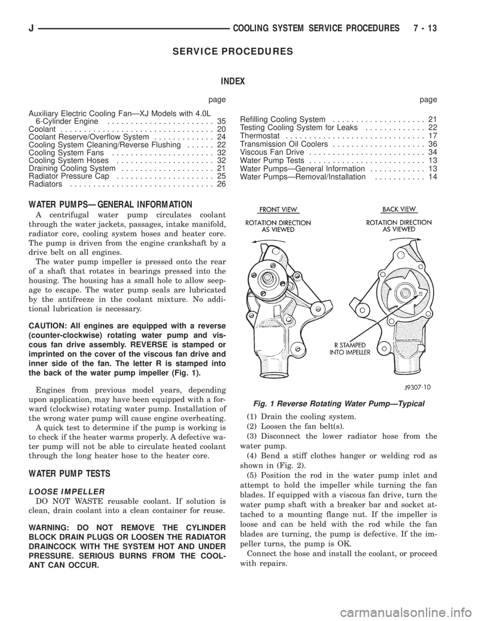
the back of the water pump impeller (Fig. 1).
Engines from previous model years, depending
upon application, may have been equipped with a for-
ward (clockwise) rotating water pump. Installation of
the wrong water pump will cause engine overheating.
A quick test to determine if the pump is working is
to check if the heater warms properly. A defective wa-
ter pump will not be able to circulate heated coolant
through the long heater hose to the heater core.
WATER PUMP TESTS
LOOSE IMPELLER
DO NOT WASTE reusable coolant. If solution is
clean, drain coolant into a clean container for reuse.
WARNING: DO NOT REMOVE THE CYLINDER
BLOCK DRAIN PLUGS OR LOOSEN THE RADIATOR
DRAINCOCK WITH THE SYSTEM HOT AND UNDER
PRESSURE. SERIOUS BURNS FROM THE COOL-
ANT CAN OCCUR.(1) Drain the cooling system.
(2) Loosen the fan belt(s).
(3) Disconnect the lower radiator hose from the
water pump.
(4) Bend a stiff clothes hanger or welding rod as
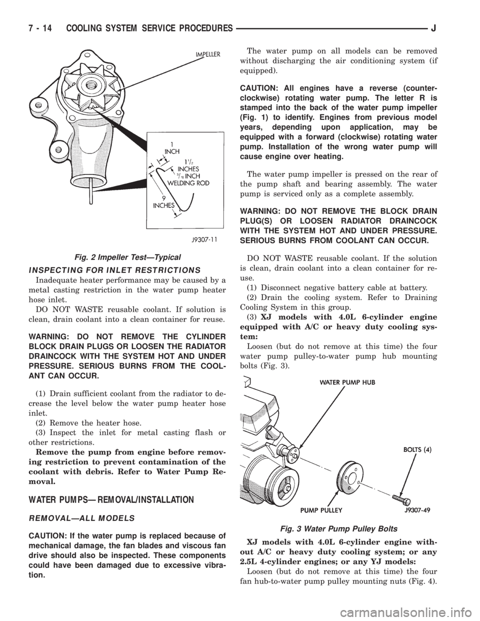
shown in (Fig. 2).
(5) Position the rod in the water pump inlet and
attempt to hold the impeller while turning the fan
blades. If equipped with a viscous fan drive, turn the
water pump shaft with a breaker bar and socket at-
tached to a mounting flange nut. If the impeller is
loose and can be held with the rod while the fan
blades are turning, the pump is defective. If the im-
peller turns, the pump is OK.
Connect the hose and install the coolant, or proceed
with repairs.
Fig. 1 Reverse Rotating Water PumpÐTypical
JCOOLING SYSTEM SERVICE PROCEDURES 7 - 13
Page 253 of 2158
INSPECTING FOR INLET RESTRICTIONS
Inadequate heater performance may be caused by a
metal casting restriction in the water pump heater
hose inlet.
DO NOT WASTE reusable coolant. If solution is
clean, drain coolant into a clean container for reuse.
WARNING: DO NOT REMOVE THE CYLINDER
BLOCK DRAIN PLUGS OR LOOSEN THE RADIATOR
DRAINCOCK WITH THE SYSTEM HOT AND UNDER
PRESSURE. SERIOUS BURNS FROM THE COOL-
ANT CAN OCCUR.
(1) Drain sufficient coolant from the radiator to de-
crease the level below the water pump heater hose
inlet.
(2) Remove the heater hose.
(3) Inspect the inlet for metal casting flash or
other restrictions.
Remove the pump from engine before remov-
ing restriction to prevent contamination of the
coolant with debris. Refer to Water Pump Re-
moval.
WATER PUMPSÐREMOVAL/INSTALLATION
REMOVALÐALL MODELS
CAUTION: If the water pump is replaced because of
mechanical damage, the fan blades and viscous fan
drive should also be inspected. These components
could have been damaged due to excessive vibra-
tion.The water pump on all models can be removed
without discharging the air conditioning system (if
equipped).
CAUTION: All engines have a reverse (counter-
clockwise) rotating water pump. The letter R is
stamped into the back of the water pump impeller
(Fig. 1) to identify. Engines from previous model
years, depending upon application, may be
equipped with a forward (clockwise) rotating water
pump. Installation of the wrong water pump will
cause engine over heating.
The water pump impeller is pressed on the rear of
the pump shaft and bearing assembly. The water
pump is serviced only as a complete assembly.
WARNING: DO NOT REMOVE THE BLOCK DRAIN
PLUG(S) OR LOOSEN RADIATOR DRAINCOCK
WITH THE SYSTEM HOT AND UNDER PRESSURE.
SERIOUS BURNS FROM COOLANT CAN OCCUR.
DO NOT WASTE reusable coolant. If the solution
is clean, drain coolant into a clean container for re-
use.
(1) Disconnect negative battery cable at battery.
(2) Drain the cooling system. Refer to Draining
Cooling System in this group.
(3)XJ models with 4.0L 6-cylinder engine
equipped with A/C or heavy duty cooling sys-
tem:
Loosen (but do not remove at this time) the four
water pump pulley-to-water pump hub mounting
bolts (Fig. 3).
XJ models with 4.0L 6-cylinder engine with-
out A/C or heavy duty cooling system; or any
2.5L 4-cylinder engines; or any YJ models:
Loosen (but do not remove at this time) the four
fan hub-to-water pump pulley mounting nuts (Fig. 4).
Fig. 2 Impeller TestÐTypical
Fig. 3 Water Pump Pulley Bolts
7 - 14 COOLING SYSTEM SERVICE PROCEDURESJ
Page 254 of 2158
The engine accessory drive belt must be removed
prior to removing the fan (if installed at pump) or
fan pulley.
(4) Remove engine drive belt as follows:
(a) Loosen two rear power steering pump mount-
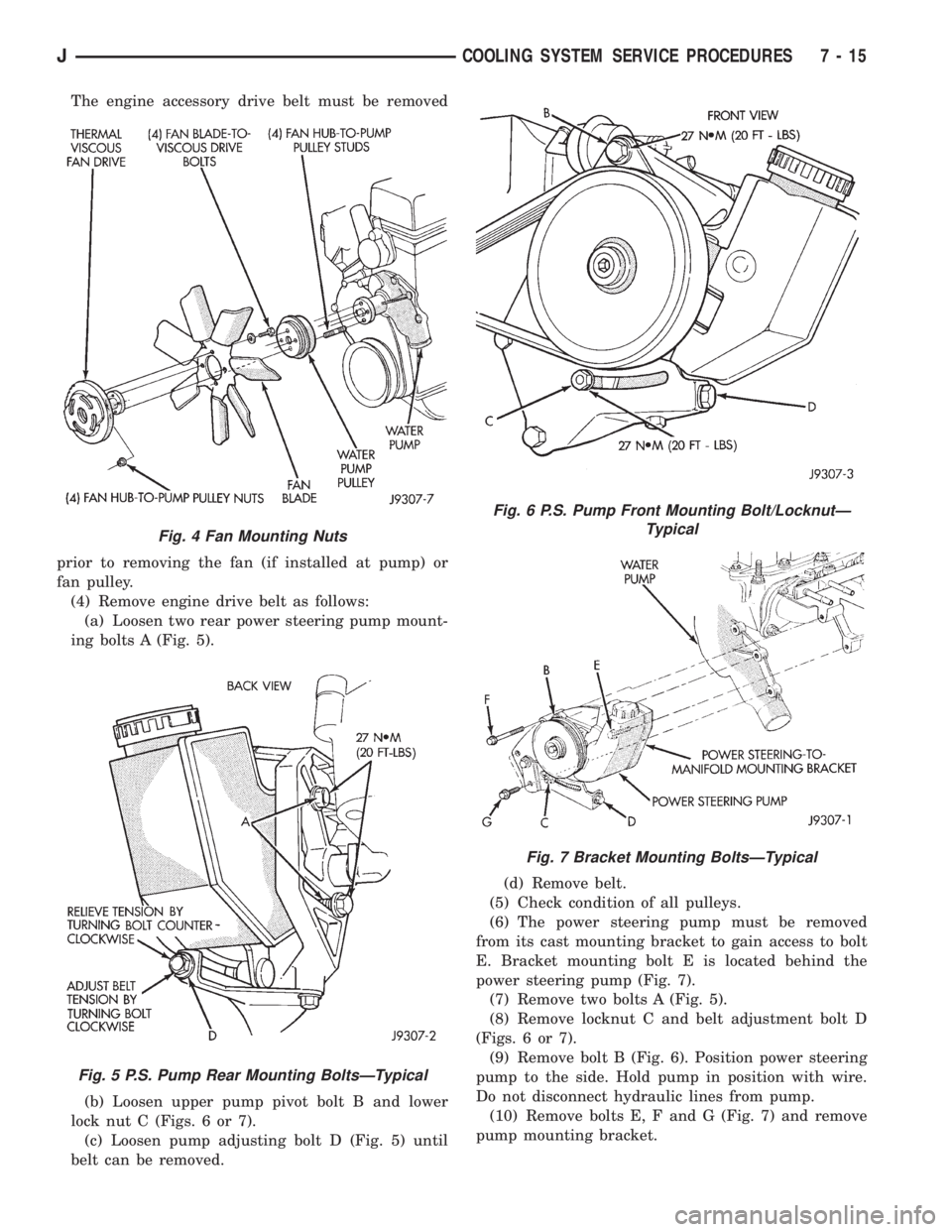
ing bolts A (Fig. 5).
(b) Loosen upper pump pivot bolt B and lower
lock nut C (Figs. 6 or 7).
(c) Loosen pump adjusting bolt D (Fig. 5) until
belt can be removed.(d) Remove belt.
(5) Check condition of all pulleys.
(6) The power steering pump must be removed
from its cast mounting bracket to gain access to bolt
E. Bracket mounting bolt E is located behind the
power steering pump (Fig. 7).
(7) Remove two bolts A (Fig. 5).
(8) Remove locknut C and belt adjustment bolt D
(Figs. 6 or 7).
(9) Remove bolt B (Fig. 6). Position power steering
pump to the side. Hold pump in position with wire.
Do not disconnect hydraulic lines from pump.
(10) Remove bolts E, F and G (Fig. 7) and remove
pump mounting bracket.
Fig. 4 Fan Mounting Nuts
Fig. 5 P.S. Pump Rear Mounting BoltsÐTypical
Fig. 6 P.S. Pump Front Mounting Bolt/LocknutÐ
Typical
Fig. 7 Bracket Mounting BoltsÐTypical
JCOOLING SYSTEM SERVICE PROCEDURES 7 - 15
Page 256 of 2158
INSTALLATIONÐALL MODELS
(1) If pump is being replaced, install the heater
hose fitting to the pump. Use a sealant on the fitting
such as MoparŸ Thread Sealant With Teflon. Refer
to the directions on the package.
(2) Clean the gasket mating surfaces. If the origi-
nal pump is used, remove any deposits or other for-
eign material. Inspect the cylinder block and water
pump mating surfaces for erosion or damage from
cavitation.
(3) Install the gasket and water pump. The silicone
bead on the gasket should be facing the water pump.
Also, the gasket is installed dry. Tighten mounting
bolts to 30 Nzm (22 ft. lbs.) torque. Rotate the shaft
by hand to be sure it turns freely.
(4) Connect the radiator and heater hoses to the
water pump.
(5) Position water pump pulley to water pump hub.
(6) If equipped with a water pump mounted fan,
install fan and four nuts to water pump hub. If not
equipped with a water pump mounted fan, install
four pump hub bolts. Tighten bolts (or nuts) to 27
Nzm (20 ft. lbs.) torque.
(7) Position power steering pump bracket to en-
gine. Install bolts E, F and G (Fig. 7). Tighten bolts F
andGto38Nzm (28 ft. lbs.) torque. Tighten bolt E to
27 Nzm (20 ft. lbs.) torque.
(8) Position power steering pump to mounting
bracket. Install pivot bolt B (Fig. 6) finger tight. In-
stall locknut C and adjustment bolt D (Figs. 6 or 7)
finger tight.
(9) Install two adjustment bolts A (Fig. 6) finger
tight.
(10) Install idler pulley.
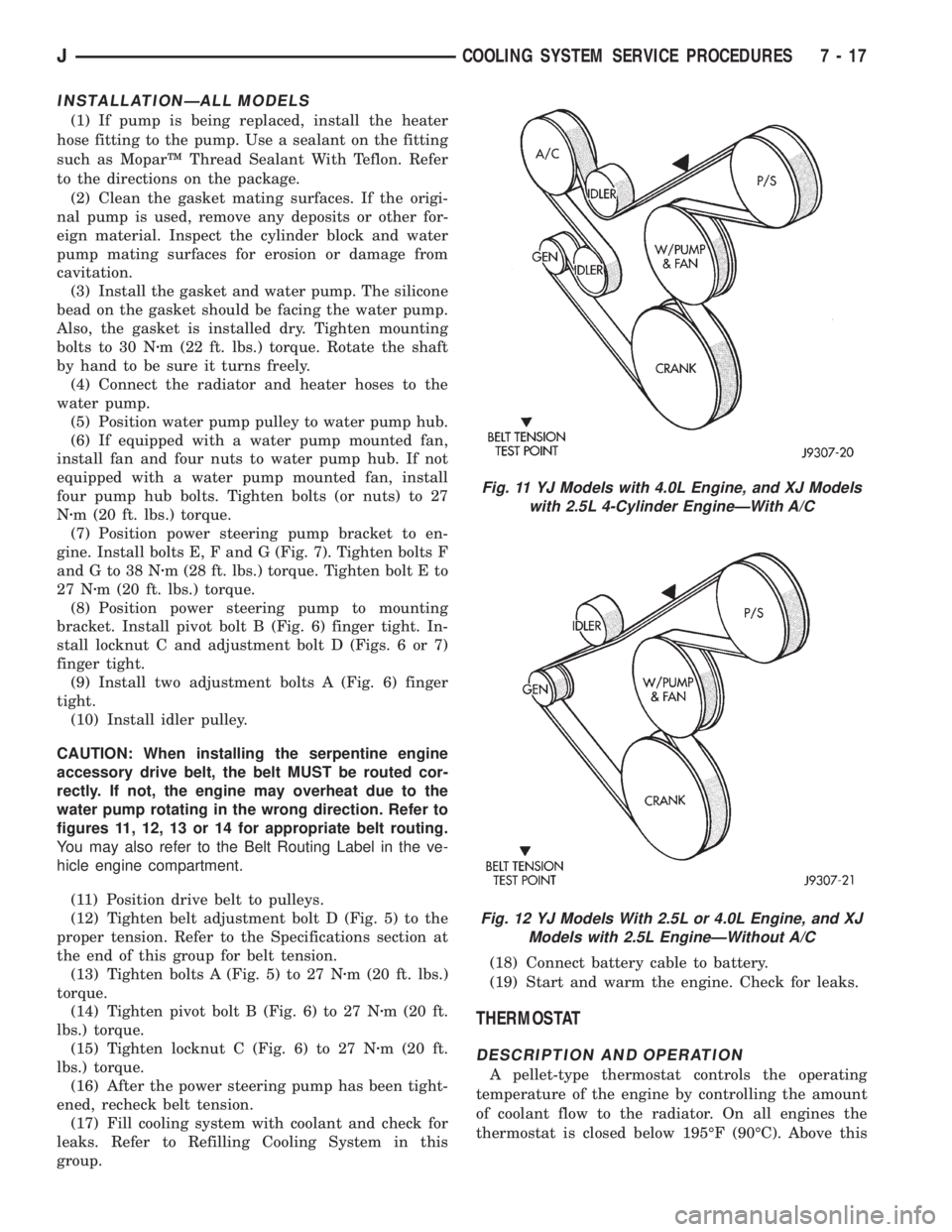
CAUTION: When installing the serpentine engine
accessory drive belt, the belt MUST be routed cor-
rectly. If not, the engine may overheat due to the
water pump rotating in the wrong direction. Refer to
figures 11, 12, 13 or 14 for appropriate belt routing.
You may also refer to the Belt Routing Label in the ve-
hicle engine compartment.
(11) Position drive belt to pulleys.
(12) Tighten belt adjustment bolt D (Fig. 5) to the
proper tension. Refer to the Specifications section at
the end of this group for belt tension.
(13) Tighten bolts A (Fig. 5) to 27 Nzm (20 ft. lbs.)
torque.
(14) Tighten pivot bolt B (Fig. 6) to 27 Nzm (20 ft.
lbs.) torque.
(15) Tighten locknut C (Fig. 6) to 27 Nzm (20 ft.
lbs.) torque.
(16) After the power steering pump has been tight-
ened, recheck belt tension.
(17) Fill cooling system with coolant and check for
leaks. Refer to Refilling Cooling System in this
group.(18) Connect battery cable to battery.
(19) Start and warm the engine. Check for leaks.
THERMOSTAT
DESCRIPTION AND OPERATION
A pellet-type thermostat controls the operating
temperature of the engine by controlling the amount
of coolant flow to the radiator. On all engines the
thermostat is closed below 195ÉF (90ÉC). Above this
Fig. 11 YJ Models with 4.0L Engine, and XJ Models
with 2.5L 4-Cylinder EngineÐWith A/C
Fig. 12 YJ Models With 2.5L or 4.0L Engine, and XJ
Models with 2.5L EngineÐWithout A/C
JCOOLING SYSTEM SERVICE PROCEDURES 7 - 17