1995 JEEP XJ engine
[x] Cancel search: enginePage 195 of 2158
HCU INSTALLATION (XJ)
(1) Install HCU as follows:
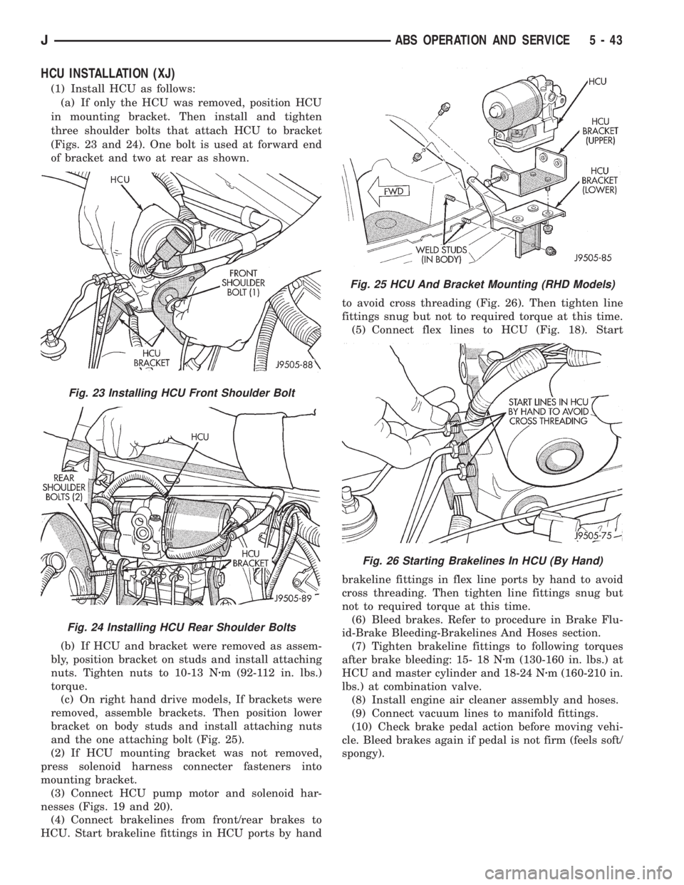
(a) If only the HCU was removed, position HCU
in mounting bracket. Then install and tighten
three shoulder bolts that attach HCU to bracket
(Figs. 23 and 24). One bolt is used at forward end
of bracket and two at rear as shown.
(b) If HCU and bracket were removed as assem-
bly, position bracket on studs and install attaching
nuts. Tighten nuts to 10-13 Nzm (92-112 in. lbs.)
torque.
(c) On right hand drive models, If brackets were
removed, assemble brackets. Then position lower
bracket on body studs and install attaching nuts
and the one attaching bolt (Fig. 25).
(2) If HCU mounting bracket was not removed,
press solenoid harness connecter fasteners into
mounting bracket.
(3) Connect HCU pump motor and solenoid har-
nesses (Figs. 19 and 20).
(4) Connect brakelines from front/rear brakes to
HCU. Start brakeline fittings in HCU ports by handto avoid cross threading (Fig. 26). Then tighten line
fittings snug but not to required torque at this time.
(5) Connect flex lines to HCU (Fig. 18). Start
brakeline fittings in flex line ports by hand to avoid
cross threading. Then tighten line fittings snug but
not to required torque at this time.
(6) Bleed brakes. Refer to procedure in Brake Flu-
id-Brake Bleeding-Brakelines And Hoses section.
(7) Tighten brakeline fittings to following torques
after brake bleeding: 15- 18 Nzm (130-160 in. lbs.) at
HCU and master cylinder and 18-24 Nzm (160-210 in.
lbs.) at combination valve.
(8) Install engine air cleaner assembly and hoses.
(9) Connect vacuum lines to manifold fittings.
(10) Check brake pedal action before moving vehi-
cle. Bleed brakes again if pedal is not firm (feels soft/
spongy).
Fig. 23 Installing HCU Front Shoulder Bolt
Fig. 24 Installing HCU Rear Shoulder Bolts
Fig. 25 HCU And Bracket Mounting (RHD Models)
Fig. 26 Starting Brakelines In HCU (By Hand)
JABS OPERATION AND SERVICE 5 - 43
Page 196 of 2158
HCU REMOVAL (YJ)
(1) Place shop towels under master cylinder and
HCU brakelines.
(2) Disconnect flex lines at upper part of HCU.
(3) Disconnect solenoid and pump harness wires at
HCU harness connecters.
(4) Disconnect lines to front/rear brakes at lower
part of HCU.
(5) Remove shoulder bolts attaching HCU to
mounting bracket and remove HCU.
HCU INSTALLATION (YJ)
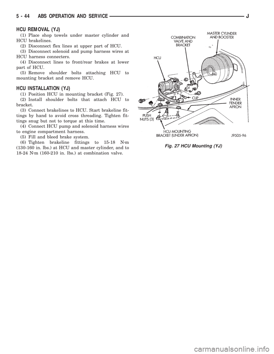
(1) Position HCU in mounting bracket (Fig. 27).
(2) Install shoulder bolts that attach HCU to
bracket.
(3) Connect brakelines to HCU. Start brakeline fit-
tings by hand to avoid cross threading. Tighten fit-
tings snug but not to torque at this time.
(4) Connect HCU pump and solenoid harness wires
to engine compartment harness.
(5) Fill and bleed brake system.
(6) Tighten brakeline fittings to 15-18 Nzm
(130-160 in. lbs.) at HCU and master cylinder, and to
18-24 Nzm (160-210 in. lbs.) at combination valve.
Fig. 27 HCU Mounting (YJ)
5 - 44 ABS OPERATION AND SERVICEJ
Page 218 of 2158
PARKING BRAKE CABLE TENSIONER
REPLACEMENT (XJ)
(1) Raise vehicle.
(2) Remove adjuster nut from tensioner rod. Secure
equalizer and cables to nearby chassis component
with wire.
(3) Remove nuts attaching lever assembly to sup-
port plate and floorpan.
(4) Lower vehicle.
(5) Remove console components and lever assembly
cover.
(6) Remove lever and tensioner assembly.
(7) Move cover and boot for access to tensioner re-
taining pin.
(8) Remove E-clip and pin that attach tensioner to
lever arm (Fig. 4).
(9) Remove tensioner from cover.
(10) Transfer boot to new tensioner if necessary.
(11) Attach tensioner to lever arm with pin and E-
clip.
(12) Verify that E-clip is fully engaged in pin (Fig.
4).
(13) Align cover and seal on lever flange.
(14) Verify that tensioner boot is seated in cover
(Fig. 6).
(15) Install assembled lever and tensioner in floor-
pan.
(16) Install necessary console components.
(17) Adjust parking brakes as described in this sec-
tion.
PARKING BRAKE PEDAL REMOVAL (YJ)
(1) Raise vehicle.
(2) Loosen equalizer nuts until front cable is slack
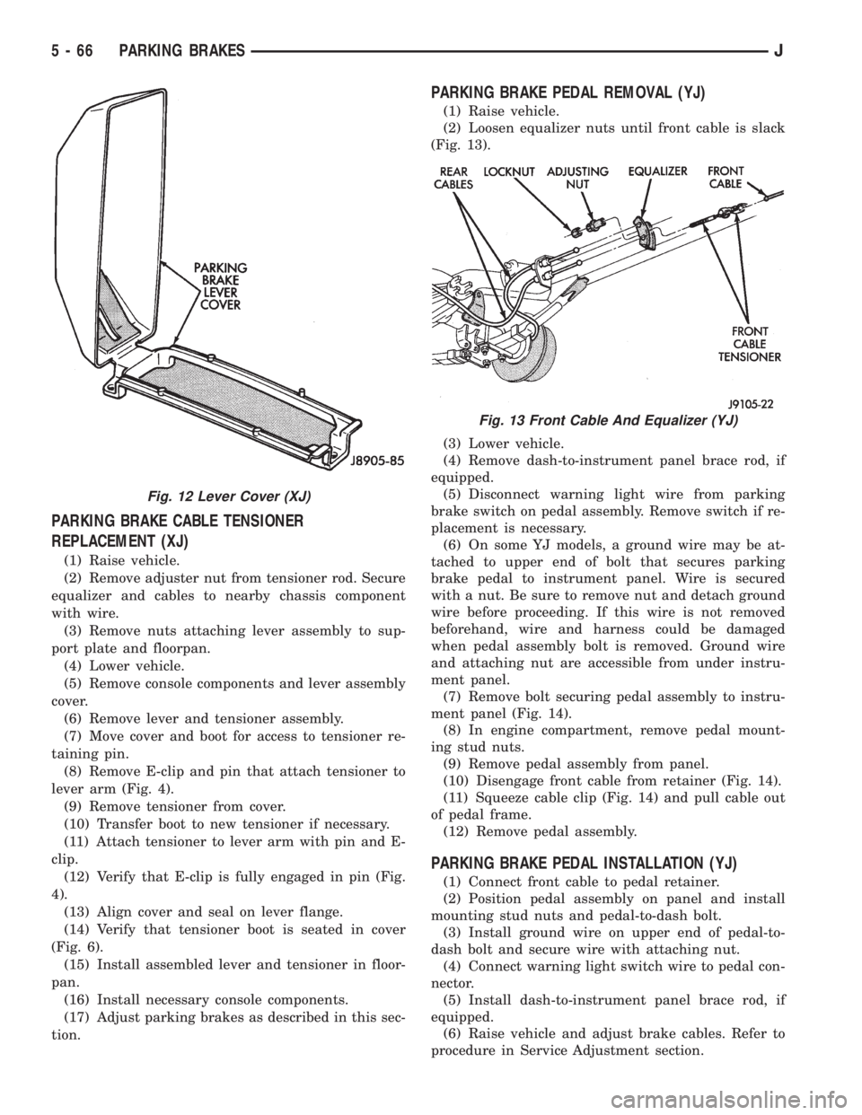
(Fig. 13).
(3) Lower vehicle.
(4) Remove dash-to-instrument panel brace rod, if
equipped.
(5) Disconnect warning light wire from parking
brake switch on pedal assembly. Remove switch if re-
placement is necessary.
(6) On some YJ models, a ground wire may be at-
tached to upper end of bolt that secures parking
brake pedal to instrument panel. Wire is secured
with a nut. Be sure to remove nut and detach ground
wire before proceeding. If this wire is not removed
beforehand, wire and harness could be damaged
when pedal assembly bolt is removed. Ground wire
and attaching nut are accessible from under instru-
ment panel.
(7) Remove bolt securing pedal assembly to instru-
ment panel (Fig. 14).
(8) In engine compartment, remove pedal mount-
ing stud nuts.
(9) Remove pedal assembly from panel.
(10) Disengage front cable from retainer (Fig. 14).
(11) Squeeze cable clip (Fig. 14) and pull cable out
of pedal frame.
(12) Remove pedal assembly.
PARKING BRAKE PEDAL INSTALLATION (YJ)
(1) Connect front cable to pedal retainer.
(2) Position pedal assembly on panel and install
mounting stud nuts and pedal-to-dash bolt.
(3) Install ground wire on upper end of pedal-to-
dash bolt and secure wire with attaching nut.
(4) Connect warning light switch wire to pedal con-
nector.
(5) Install dash-to-instrument panel brace rod, if
equipped.
(6) Raise vehicle and adjust brake cables. Refer to
procedure in Service Adjustment section.
Fig. 12 Lever Cover (XJ)
Fig. 13 Front Cable And Equalizer (YJ)
5 - 66 PARKING BRAKESJ
Page 226 of 2158
when handling the cover and disc. Impact can distort
the cover, diaphragm spring, release fingers and the
hub of the clutch disc.
Use an alignment tool when positioning the disc on
the flywheel. The tool prevents accidental misalign-
ment which could result in cover distortion and disc
damage.
A frequent cause of clutch cover distortion (and
consequent misalignment) is improper bolt tighten-
ing. To avoid warping the cover, the bolts must tight-
ened alternately (diagonal pattern) and evenly (2-3
threads at a time) to specified torque.
CLUTCH HOUSING MISALIGNMENT
Clutch housing alignment is important to proper
clutch operation. The housing maintains alignment
between the crankshaft and transmission input
shaft. Misalignment can cause clutch noise, hard
shifting, incomplete release and chatter. It can also
result in premature wear of the pilot bearing, cover
release fingers and clutch disc. In severe cases, mis-
alignment can also cause premature wear of the
transmission input shaft and front bearing.
Housing misalignment is generally caused by incor-
rect seating on the engine or transmission, loose
housing bolts, missing alignment dowels, or housing
damage. Infrequently, misalignment may also be
caused by housing mounting surfaces that are not
completely parallel. Misalignment can be corrected
with shims.
INSTALLATION METHODS AND PARTS USAGE
Distortion of clutch components during installation
and the use of non-standard components are addi-
tional causes of clutch malfunction.Improper clutch cover bolt tightening can distort
the cover. The usual result is clutch grab, chatter
and rapid wear. Tighten the cover bolts as described
in Clutch Service section.
An improperly seated flywheel and/or clutch hous-
ing are additional causes of clutch failure. Improper
seating will produce misalignment and additional
clutch problems.
The use of non-standard or low quality parts will
also lead to problems and wear. Use recommended
factory quality parts to avoid comebacks.
A cocked pilot bearing is another cause of clutch
noise, drag, and hard shifting, and rapid bearing
wear. Always use an alignment tool to install a new
bearing. This practice helps avoid cocking the bear-
ing during installation.
INSPECTION AND DIAGNOSIS CHARTS
The clutch inspection chart (Fig. 1) outlines items
to be checked before and during clutch installation.
Use the chart as a check list to help avoid overlook-
ing potential problem sources during service opera-
tions.
The diagnosis charts describe common clutch prob-
lems, causes and correction. Fault conditions are
listed at the top of each chart. Conditions, causes and
corrective action are outlined in the indicated col-
umns.
The charts are provided as a convenient reference
when diagnosing faulty clutch operation.
6 - 4 CLUTCH DIAGNOSISJ
Page 233 of 2158
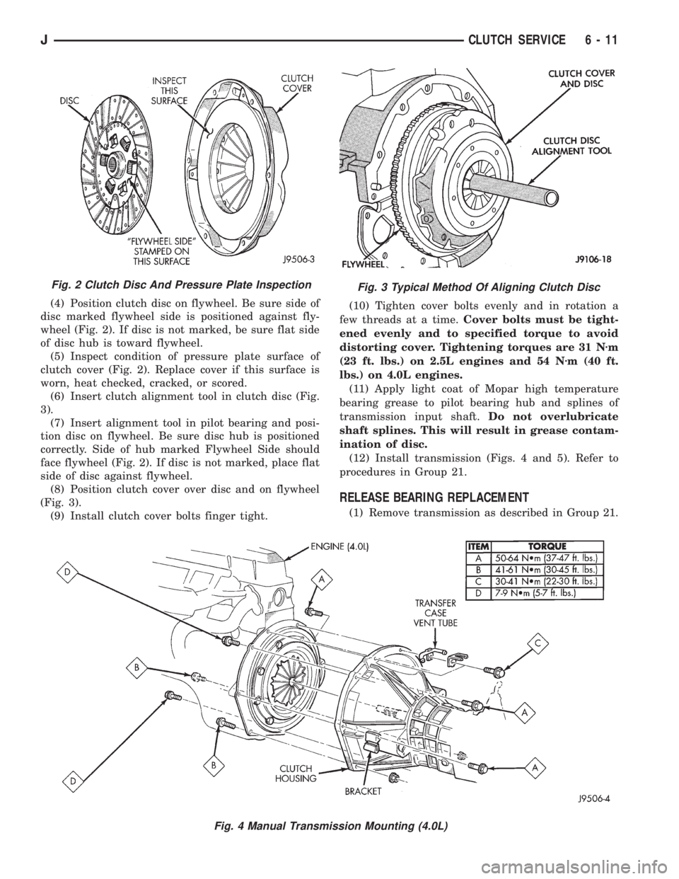
(4) Position clutch disc on flywheel. Be sure side of
disc marked flywheel side is positioned against fly-
wheel (Fig. 2). If disc is not marked, be sure flat side
of disc hub is toward flywheel.
(5) Inspect condition of pressure plate surface of
clutch cover (Fig. 2). Replace cover if this surface is
worn, heat checked, cracked, or scored.
(6) Insert clutch alignment tool in clutch disc (Fig.
3).
(7) Insert alignment tool in pilot bearing and posi-
tion disc on flywheel. Be sure disc hub is positioned
correctly. Side of hub marked Flywheel Side should
face flywheel (Fig. 2). If disc is not marked, place flat
side of disc against flywheel.
(8) Position clutch cover over disc and on flywheel
(Fig. 3).
(9) Install clutch cover bolts finger tight.(10) Tighten cover bolts evenly and in rotation a
few threads at a time.Cover bolts must be tight-
ened evenly and to specified torque to avoid
distorting cover. Tightening torques are 31 Nzm
(23 ft. lbs.) on 2.5L engines and 54 Nzm (40 ft.
lbs.) on 4.0L engines.
(11) Apply light coat of Mopar high temperature
bearing grease to pilot bearing hub and splines of
transmission input shaft.Do not overlubricate
shaft splines. This will result in grease contam-
ination of disc.
(12) Install transmission (Figs. 4 and 5). Refer to
procedures in Group 21.
RELEASE BEARING REPLACEMENT
(1) Remove transmission as described in Group 21.
Fig. 2 Clutch Disc And Pressure Plate InspectionFig. 3 Typical Method Of Aligning Clutch Disc
Fig. 4 Manual Transmission Mounting (4.0L)
JCLUTCH SERVICE 6 - 11
Page 235 of 2158
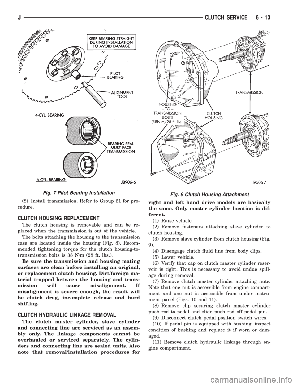
(8) Install transmission. Refer to Group 21 for pro-
cedure.
CLUTCH HOUSING REPLACEMENT
The clutch housing is removable and can be re-
placed when the transmission is out of the vehicle.
The bolts attaching the housing to the transmission
case are located inside the housing (Fig. 8). Recom-
mended tightening torque for the clutch housing-to-
transmission bolts is 38 Nzm (28 ft. lbs.).
Be sure the transmission and housing mating
surfaces are clean before installing an original,
or replacement clutch housing. Dirt/foreign ma-
terial trapped between the housing and trans-
mission will cause misalignment. If
misalignment is severe enough, the result will
be clutch drag, incomplete release and hard
shifting.
CLUTCH HYDRAULIC LINKAGE REMOVAL
The clutch master cylinder, slave cylinder
and connecting line are serviced as an assem-
bly only. The linkage components cannot be
overhauled or serviced separately. The cylin-
ders and connecting line are sealed units. Also
note that removal/installation procedures forright and left hand drive models are basically
the same. Only master cylinder location is dif-
ferent.
(1) Raise vehicle.
(2) Remove fasteners attaching slave cylinder to
clutch housing.
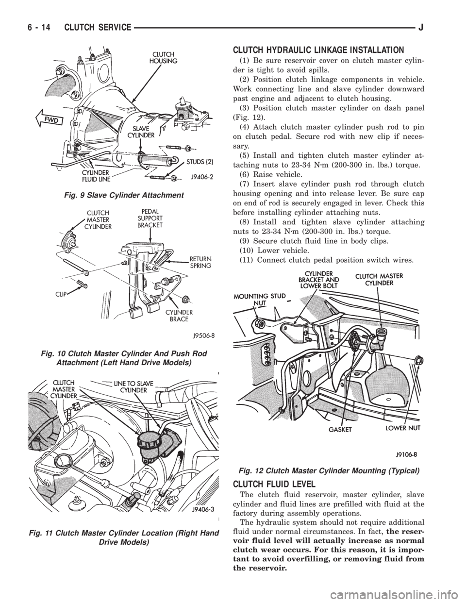
(3) Remove slave cylinder from clutch housing (Fig.
9).
(4) Disengage clutch fluid line from body clips.
(5) Lower vehicle.
(6) Verify that cap on clutch master cylinder reser-
voir is tight. This is necessary to avoid undue spill-
age during removal.
(7) Remove clutch master cylinder attaching nuts.
Note that one nut is accessible from engine compart-
ment and one nut is accessible from under instru-
ment panel (Figs. 10 and 11).
(8) Remove clip securing clutch master cylinder
push rod to pedal and slide push rod off pedal pin.
(9) Disconnect clutch pedal position switch wires.
(10) If pedal pin is equipped with bushing, inspect
condition of bushing and replace it if worn or dam-
aged.
(11) Remove clutch hydraulic linkage through en-
gine compartment.
Fig. 8 Clutch Housing AttachmentFig. 7 Pilot Bearing Installation
JCLUTCH SERVICE 6 - 13
Page 236 of 2158
CLUTCH HYDRAULIC LINKAGE INSTALLATION
(1) Be sure reservoir cover on clutch master cylin-
der is tight to avoid spills.
(2) Position clutch linkage components in vehicle.
Work connecting line and slave cylinder downward
past engine and adjacent to clutch housing.
(3) Position clutch master cylinder on dash panel
(Fig. 12).
(4) Attach clutch master cylinder push rod to pin
on clutch pedal. Secure rod with new clip if neces-
sary.
(5) Install and tighten clutch master cylinder at-
taching nuts to 23-34 Nzm (200-300 in. lbs.) torque.
(6) Raise vehicle.
(7) Insert slave cylinder push rod through clutch
housing opening and into release lever. Be sure cap
on end of rod is securely engaged in lever. Check this
before installing cylinder attaching nuts.
(8) Install and tighten slave cylinder attaching
nuts to 23-34 Nzm (200-300 in. lbs.) torque.
(9) Secure clutch fluid line in body clips.
(10) Lower vehicle.
(11) Connect clutch pedal position switch wires.
CLUTCH FLUID LEVEL
The clutch fluid reservoir, master cylinder, slave
cylinder and fluid lines are prefilled with fluid at the
factory during assembly operations.
The hydraulic system should not require additional
fluid under normal circumstances. In fact,the reser-
voir fluid level will actually increase as normal
clutch wear occurs. For this reason, it is impor-
tant to avoid overfilling, or removing fluid from
the reservoir.
Fig. 9 Slave Cylinder Attachment
Fig. 10 Clutch Master Cylinder And Push Rod
Attachment (Left Hand Drive Models)
Fig. 11 Clutch Master Cylinder Location (Right Hand
Drive Models)
Fig. 12 Clutch Master Cylinder Mounting (Typical)
6 - 14 CLUTCH SERVICEJ
Page 240 of 2158
COOLING SYSTEM
CONTENTS
page page
DIAGNOSIS............................. 4
ENGINE ACCESSORY DRIVE BELTS......... 38
ENGINE BLOCK HEATER.................. 44GENERAL INFORMATION.................. 1
SERVICE PROCEDURES.................. 13
SPECIFICATIONS........................ 45
GENERAL INFORMATION
Throughout this group, references are made to par-
ticular vehicle models by alphabetical designation
(XJ or YJ) or by the particular vehicle nameplate. A
chart showing a breakdown of alphabetical designa-
tions is included in the Introduction section at the
beginning of this manual.
COOLING SYSTEM
The cooling system regulates engine operating tem-
perature. It allows the engine to reach normal oper-
ating temperature as quickly as possible, maintains
normal operating temperature and prevents over-
heating.
The cooling system also provides a means of heat-
ing the passenger compartment and cooling the auto-
matic transmission fluid (if equipped). The cooling
system is pressurized and uses a centrifugal water
pump to circulate coolant throughout the system.
An optional factory installed heavy duty cooling
package is available on most models. The package
consists of a radiator that has an increased number
of cooling fins. XJ models equipped with a 4.0L 6-cyl-inder engine and heavy duty cooling and/or air con-
ditioning also have an auxiliary electric cooling fan.
COOLING SYSTEM COMPONENTS
The cooling system consists of:
²A radiator
²Cooling fan (mechanical and/or electrical)
²Thermal viscous fan drive
²Fan shroud
²Radiator pressure cap
²Thermostat
²Coolant reserve/overflow system
²Transmission oil cooler (if equipped with an auto-
matic transmission)
²Coolant
²Water pump
²Hoses and hose clamps
SYSTEM COOLANT ROUTING
For cooling system flow routings, refer to Figs. 1, 2,
3or4.
JCOOLING SYSTEM 7 - 1