1995 JEEP XJ engine
[x] Cancel search: enginePage 276 of 2158

The auxiliary oil coolers on all models operate in
conjunction with the internal radiator mounted main
oil cooler. The transmission oil is routed through the
main cooler first, then the auxiliary cooler, before re-
turning to the transmission.REMOVAL/INSTALLATIONÐXJ MODELS
(1) Remove the grill mounting screws and remove
the grill. Refer to Group 23, Body for procedures.
(2) Place a drain pan below the transmission oil
cooler.
(3) Remove the two hose clamps at oil cooler inlet
and outlet tubes (Figs. 45 or 46).
(4) Remove the two oil cooler mounting bolts (Figs.
45 or 46).
(5) Remove the oil cooler from vehicle.
(6) Reverse the preceding operation for installa-
tion. Tighten the two clamps 2 Nzm (15 in. lbs.)
torque. Tighten mounting bolts to 8 Nzm (72 in. lbs.)
torque.
REMOVAL/INSTALLATIONÐYJ MODELS
(1) Remove fan shroud and radiator. Refer to the
Radiators section for procedures.
(2) Remove the air conditioning filter/drier mount-
ing bolts.
WARNING: BEFORE PROCEEDING WITH THE NEXT
STEP, BE SURE TO WEAR SAFETY GLASSES. THE
A/C SYSTEM IS UNDER PRESSURE EVEN WITH
THE ENGINE OFF.
(3) Remove the A/C condenser mounting bolts (Fig.
47).
(4) Carefully tilt the A/C condenser rearward for
access to the auxiliary transmission oil cooler.
(5) Place a drain pan below the oil cooler.
(6) Remove the two hose clamps at oil cooler inlet
and outlet tubes (Fig. 44).
(7) Remove the three oil cooler mounting bolts
(Fig. 44).
(8) Remove the oil cooler from vehicle.
(9) Reverse the preceding operation for installa-
tion. Tighten the two clamps 2 Nzm (15 in. lbs.)
torque. Tighten mounting bolts to 8 Nzm (72 in. lbs.)
torque.
Fig. 45 Auxiliary Air-To-Oil CoolerÐXJ ModelsÐ4.0L
Engine
Fig. 46 Auxiliary Air-To-Oil CoolerÐXJ ModelsÐ2.5L
Engine
Fig. 47 Condenser Mounting BoltsÐYJ Models
JCOOLING SYSTEM SERVICE PROCEDURES 7 - 37
Page 277 of 2158
ENGINE ACCESSORY DRIVE BELTS
INDEX
page page
Automatic Belt TensionerÐXJ Models with Right
Hand Drive............................ 42
Belt Diagnosis............................ 38
Belt Schematics.......................... 38
Belt ServiceÐExcept Right Hand Drive......... 40
Belt ServiceÐXJ Models with Right Hand Drive . . . 42Belt Tension Specifications.................. 38
Belt TensionÐExcept Right Hand Drive (RHD).... 38
Belt TensionÐRight Hand Drive (RHD)......... 38
General Information....................... 38
GENERAL INFORMATION
CAUTION: When installing a serpentine accessory
drive belt, the belt MUST be routed correctly. If not,
the engine may overheat due to water pump rotat-
ing in wrong direction. Refer to the appropriate en-
gine Belt Schematic in this group for the correct
belt routing. Or, refer to the Belt Routing Label lo-
cated in the engine compartment.
BELT DIAGNOSIS
When diagnosing serpentine accessory drive belts,
small cracks that run across the ribbed surface of the
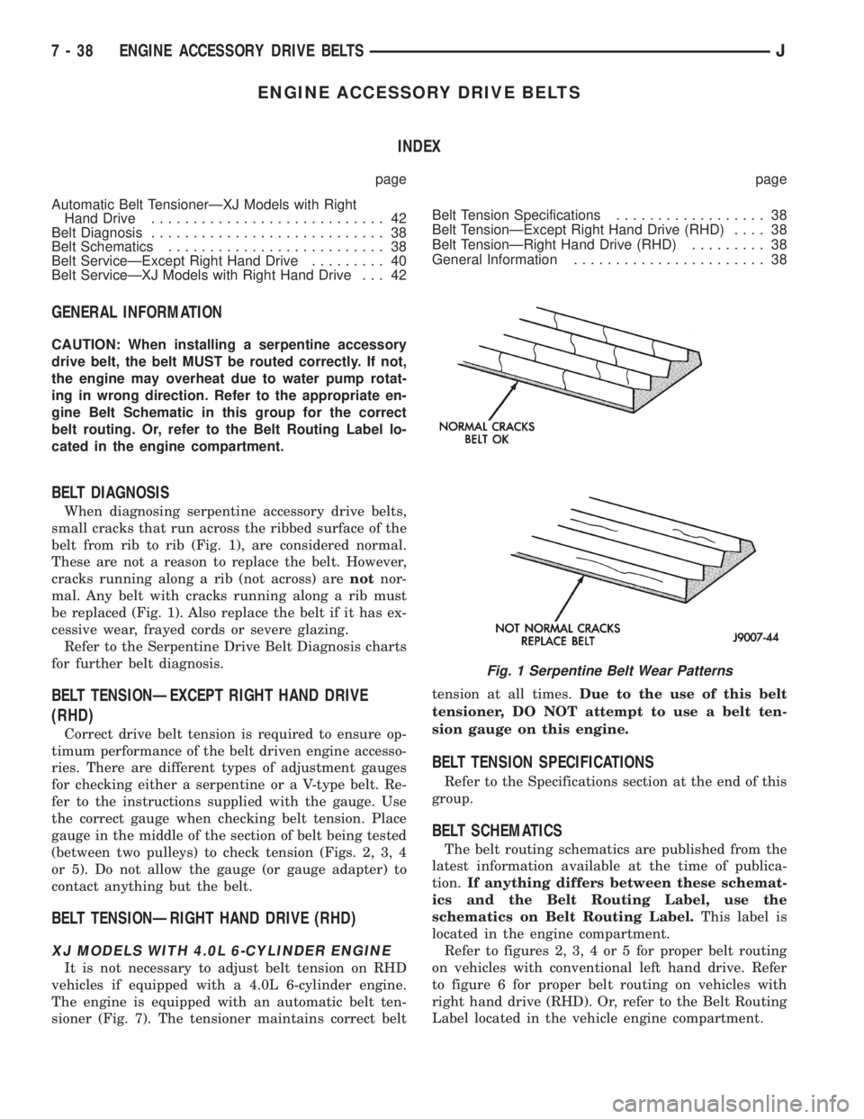
belt from rib to rib (Fig. 1), are considered normal.
These are not a reason to replace the belt. However,
cracks running along a rib (not across) arenotnor-
mal. Any belt with cracks running along a rib must
be replaced (Fig. 1). Also replace the belt if it has ex-
cessive wear, frayed cords or severe glazing.
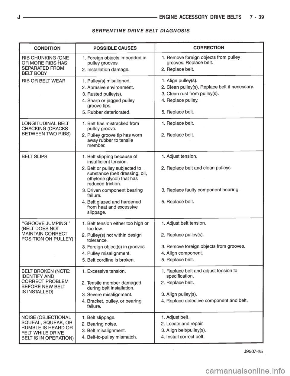
Refer to the Serpentine Drive Belt Diagnosis charts
for further belt diagnosis.
BELT TENSIONÐEXCEPT RIGHT HAND DRIVE
(RHD)
Correct drive belt tension is required to ensure op-
timum performance of the belt driven engine accesso-
ries. There are different types of adjustment gauges
for checking either a serpentine or a V-type belt. Re-
fer to the instructions supplied with the gauge. Use
the correct gauge when checking belt tension. Place
gauge in the middle of the section of belt being tested
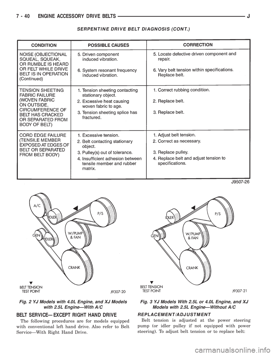
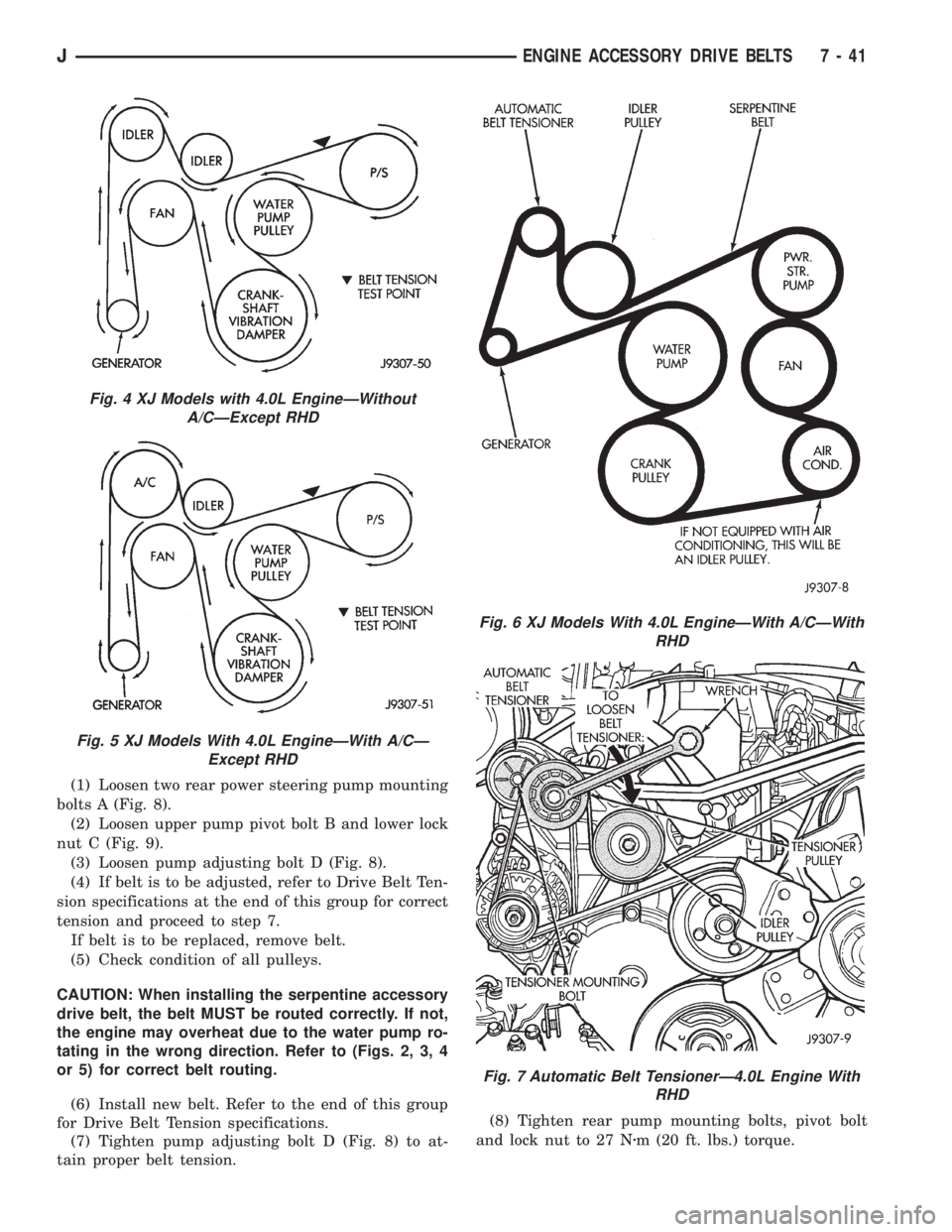
(between two pulleys) to check tension (Figs. 2, 3, 4
or 5). Do not allow the gauge (or gauge adapter) to
contact anything but the belt.
BELT TENSIONÐRIGHT HAND DRIVE (RHD)
XJ MODELS WITH 4.0L 6-CYLINDER ENGINE
It is not necessary to adjust belt tension on RHD
vehicles if equipped with a 4.0L 6-cylinder engine.
The engine is equipped with an automatic belt ten-
sioner (Fig. 7). The tensioner maintains correct belttension at all times.Due to the use of this belt
tensioner, DO NOT attempt to use a belt ten-
sion gauge on this engine.
BELT TENSION SPECIFICATIONS
Refer to the Specifications section at the end of this
group.
BELT SCHEMATICS
The belt routing schematics are published from the
latest information available at the time of publica-
tion.If anything differs between these schemat-
ics and the Belt Routing Label, use the
schematics on Belt Routing Label.This label is
located in the engine compartment.
Refer to figures 2, 3, 4 or 5 for proper belt routing
on vehicles with conventional left hand drive. Refer
to figure 6 for proper belt routing on vehicles with
right hand drive (RHD). Or, refer to the Belt Routing
Label located in the vehicle engine compartment.
Fig. 1 Serpentine Belt Wear Patterns
7 - 38 ENGINE ACCESSORY DRIVE BELTSJ
Page 278 of 2158
SERPENTINE DRIVE BELT DIAGNOSIS
JENGINE ACCESSORY DRIVE BELTS 7 - 39
Page 279 of 2158
BELT SERVICEÐEXCEPT RIGHT HAND DRIVE
The following procedures are for models equipped
with conventional left hand drive. Also refer to Belt
ServiceÐWith Right Hand Drive.
REPLACEMENT/ADJUSTMENT
Belt tension is adjusted at the power steering
pump (or idler pulley if not equipped with power
steering). To adjust belt tension or to replace belt:
SERPENTINE DRIVE BELT DIAGNOSIS (CONT.)
Fig. 2 YJ Models with 4.0L Engine, and XJ Models
with 2.5L EngineÐWith A/CFig. 3 YJ Models With 2.5L or 4.0L Engine, and XJ
Models with 2.5L EngineÐWithout A/C
7 - 40 ENGINE ACCESSORY DRIVE BELTSJ
Page 280 of 2158
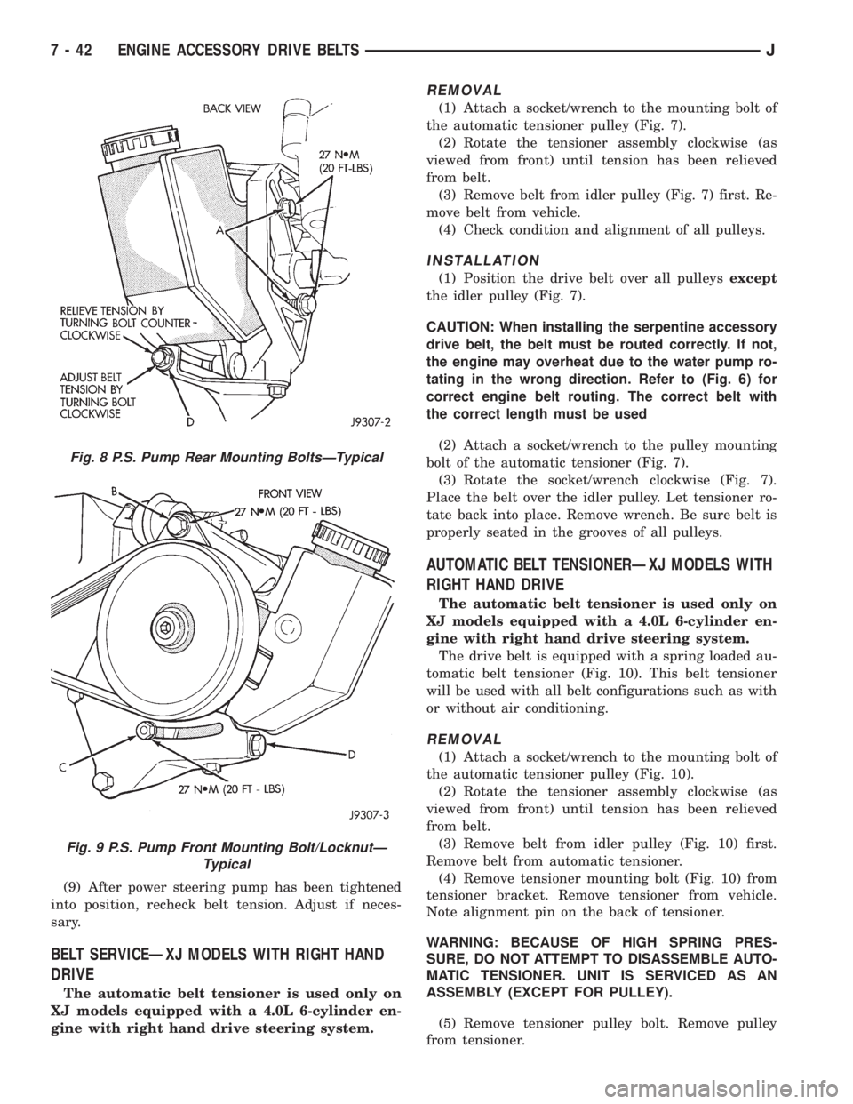
(1) Loosen two rear power steering pump mounting
bolts A (Fig. 8).
(2) Loosen upper pump pivot bolt B and lower lock
nut C (Fig. 9).
(3) Loosen pump adjusting bolt D (Fig. 8).
(4) If belt is to be adjusted, refer to Drive Belt Ten-
sion specifications at the end of this group for correct
tension and proceed to step 7.
If belt is to be replaced, remove belt.
(5) Check condition of all pulleys.
CAUTION: When installing the serpentine accessory
drive belt, the belt MUST be routed correctly. If not,
the engine may overheat due to the water pump ro-
tating in the wrong direction. Refer to (Figs. 2, 3, 4
or 5) for correct belt routing.
(6) Install new belt. Refer to the end of this group
for Drive Belt Tension specifications.
(7) Tighten pump adjusting bolt D (Fig. 8) to at-
tain proper belt tension.(8) Tighten rear pump mounting bolts, pivot bolt
and lock nut to 27 Nzm (20 ft. lbs.) torque.
Fig. 4 XJ Models with 4.0L EngineÐWithout
A/CÐExcept RHD
Fig. 5 XJ Models With 4.0L EngineÐWith A/CÐ
Except RHD
Fig. 6 XJ Models With 4.0L EngineÐWith A/CÐWith
RHD
Fig. 7 Automatic Belt TensionerÐ4.0L Engine With
RHD
JENGINE ACCESSORY DRIVE BELTS 7 - 41
Page 281 of 2158
(9) After power steering pump has been tightened
into position, recheck belt tension. Adjust if neces-
sary.
BELT SERVICEÐXJ MODELS WITH RIGHT HAND
DRIVE
The automatic belt tensioner is used only on
XJ models equipped with a 4.0L 6-cylinder en-
gine with right hand drive steering system.
REMOVAL
(1) Attach a socket/wrench to the mounting bolt of
the automatic tensioner pulley (Fig. 7).
(2) Rotate the tensioner assembly clockwise (as
viewed from front) until tension has been relieved
from belt.
(3) Remove belt from idler pulley (Fig. 7) first. Re-
move belt from vehicle.
(4) Check condition and alignment of all pulleys.
INSTALLATION
(1) Position the drive belt over all pulleysexcept
the idler pulley (Fig. 7).
CAUTION: When installing the serpentine accessory
drive belt, the belt must be routed correctly. If not,
the engine may overheat due to the water pump ro-
tating in the wrong direction. Refer to (Fig. 6) for
correct engine belt routing. The correct belt with
the correct length must be used
(2) Attach a socket/wrench to the pulley mounting
bolt of the automatic tensioner (Fig. 7).
(3) Rotate the socket/wrench clockwise (Fig. 7).
Place the belt over the idler pulley. Let tensioner ro-
tate back into place. Remove wrench. Be sure belt is
properly seated in the grooves of all pulleys.
AUTOMATIC BELT TENSIONERÐXJ MODELS WITH
RIGHT HAND DRIVE
The automatic belt tensioner is used only on
XJ models equipped with a 4.0L 6-cylinder en-
gine with right hand drive steering system.
The drive belt is equipped with a spring loaded au-
tomatic belt tensioner (Fig. 10). This belt tensioner
will be used with all belt configurations such as with
or without air conditioning.
REMOVAL
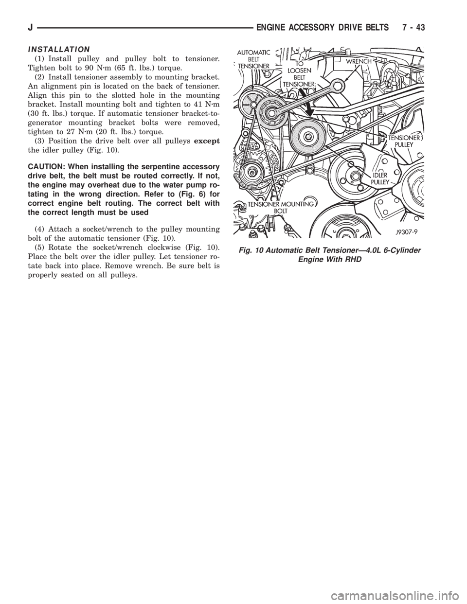
(1) Attach a socket/wrench to the mounting bolt of
the automatic tensioner pulley (Fig. 10).
(2) Rotate the tensioner assembly clockwise (as
viewed from front) until tension has been relieved
from belt.
(3) Remove belt from idler pulley (Fig. 10) first.
Remove belt from automatic tensioner.
(4) Remove tensioner mounting bolt (Fig. 10) from
tensioner bracket. Remove tensioner from vehicle.
Note alignment pin on the back of tensioner.
WARNING: BECAUSE OF HIGH SPRING PRES-
SURE, DO NOT ATTEMPT TO DISASSEMBLE AUTO-
MATIC TENSIONER. UNIT IS SERVICED AS AN
ASSEMBLY (EXCEPT FOR PULLEY).
(5) Remove tensioner pulley bolt. Remove pulley
from tensioner.
Fig. 8 P.S. Pump Rear Mounting BoltsÐTypical
Fig. 9 P.S. Pump Front Mounting Bolt/LocknutÐ
Typical
7 - 42 ENGINE ACCESSORY DRIVE BELTSJ
Page 282 of 2158
INSTALLATION
(1) Install pulley and pulley bolt to tensioner.
Tighten bolt to 90 Nzm (65 ft. lbs.) torque.
(2) Install tensioner assembly to mounting bracket.
An alignment pin is located on the back of tensioner.
Align this pin to the slotted hole in the mounting
bracket. Install mounting bolt and tighten to 41 Nzm
(30 ft. lbs.) torque. If automatic tensioner bracket-to-
generator mounting bracket bolts were removed,
tighten to 27 Nzm (20 ft. lbs.) torque.
(3) Position the drive belt over all pulleysexcept
the idler pulley (Fig. 10).
CAUTION: When installing the serpentine accessory
drive belt, the belt must be routed correctly. If not,
the engine may overheat due to the water pump ro-
tating in the wrong direction. Refer to (Fig. 6) for
correct engine belt routing. The correct belt with
the correct length must be used
(4) Attach a socket/wrench to the pulley mounting
bolt of the automatic tensioner (Fig. 10).
(5) Rotate the socket/wrench clockwise (Fig. 10).
Place the belt over the idler pulley. Let tensioner ro-
tate back into place. Remove wrench. Be sure belt is
properly seated on all pulleys.
Fig. 10 Automatic Belt TensionerÐ4.0L 6-Cylinder
Engine With RHD
JENGINE ACCESSORY DRIVE BELTS 7 - 43
Page 283 of 2158
ENGINE BLOCK HEATER
GENERAL INFORMATION
DESCRIPTION AND OPERATION
An optional engine block heater is available for all
models. The heater is equipped with a power cord.
The cord is attached to an engine compartment com-
ponent with tie-straps. The heater warms the engine
providing easier engine starting and faster warm-up
in low temperatures. The heater is mounted in a core
hole of the engine cylinder block (in place of a freeze
plug) with the heating element immersed in engine
coolant. Connect the power cord to a grounded 110-
120 volt AC electrical outlet with a grounded, three-
wire extension cord.
WARNING: DO NOT OPERATE ENGINE UNLESS
BLOCK HEATER CORD HAS BEEN DISCONNECTED
FROM POWER SOURCE AND SECURED IN PLACE.
BLOCK HEATER SPECIFICATIONS
²2.5L 4-Cylinder Engine: 115 Volts 400 Watts
²4.0L 6-Cylinder Engine: 120 Volts 600 Watts
REMOVAL
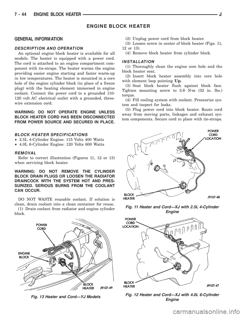
Refer to correct illustration (Figures 11, 12 or 13)
when servicing block heater.
WARNING: DO NOT REMOVE THE CYLINDER
BLOCK DRAIN PLUGS OR LOOSEN THE RADIATOR
DRAINCOCK WITH THE SYSTEM HOT AND PRES-
SURIZED. SERIOUS BURNS FROM THE COOLANT
CAN OCCUR.
DO NOT WASTE reusable coolant. If solution is
clean, drain coolant into a clean container for reuse.
(1) Drain coolant from radiator and engine cylinder
block.(2) Unplug power cord from block heater.
(3) Loosen screw in center of block heater (Figs. 11,
12 or 13).
(4) Remove block heater from cylinder block.
INSTALLATION
(1) Thoroughly clean the engine core hole and the
block heater seat.
(2) Insert block heater assembly into core hole
with element loop pointingUp.
(3) Seat block heater flush against block face.
Tighten mounting screw to 3.6 Nzm (32 in. lbs.)
torque.
(4) Fill cooling system with coolant. Pressurize sys-
tem and inspect for leaks.
(5) Plug power cord into block heater. Route cord
away from moving parts, linkages and exhaust sys-
tem components. Secure cord in place with tie-straps.
Fig. 13 Heater and CordÐYJ Models
Fig. 11 Heater and CordÐXJ with 2.5L 4-Cylinder
Engine
Fig. 12 Heater and CordÐXJ with 4.0L 6-Cylinder
Engine
7 - 44 ENGINE BLOCK HEATERJ