1995 JEEP XJ engine
[x] Cancel search: enginePage 304 of 2158
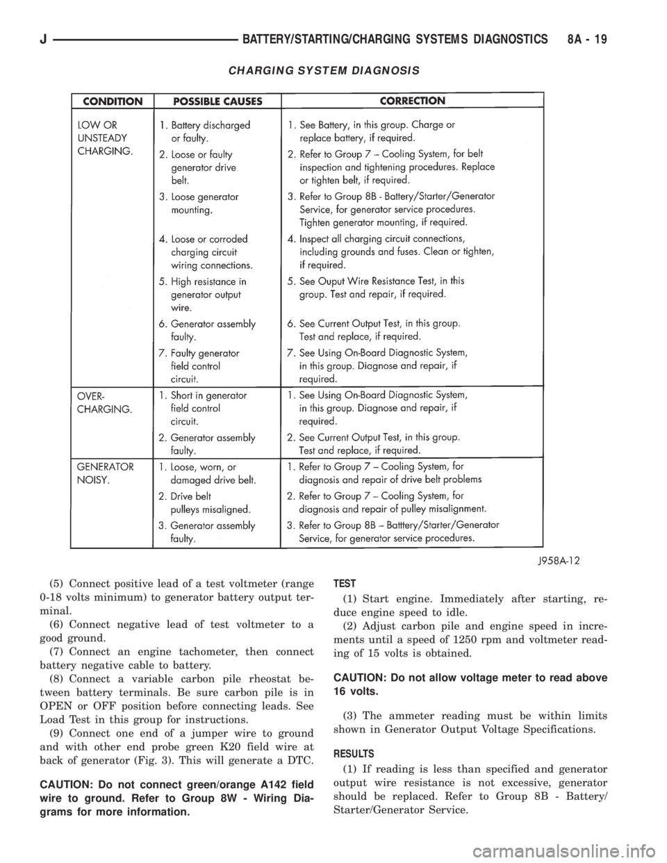
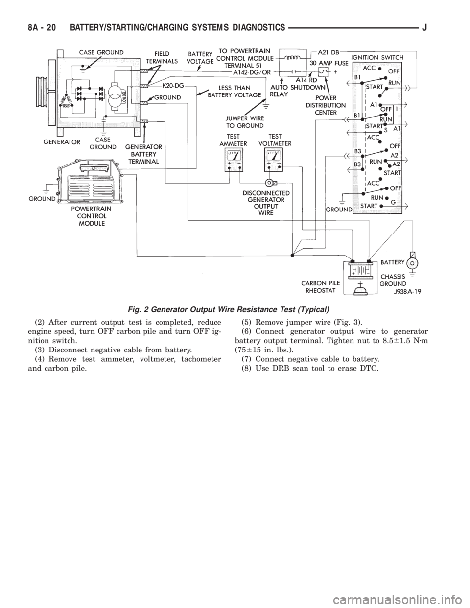
(5) Connect positive lead of a test voltmeter (range
0-18 volts minimum) to generator battery output ter-
minal.
(6) Connect negative lead of test voltmeter to a
good ground.
(7) Connect an engine tachometer, then connect
battery negative cable to battery.
(8) Connect a variable carbon pile rheostat be-
tween battery terminals. Be sure carbon pile is in
OPEN or OFF position before connecting leads. See
Load Test in this group for instructions.
(9) Connect one end of a jumper wire to ground
and with other end probe green K20 field wire at
back of generator (Fig. 3). This will generate a DTC.
CAUTION: Do not connect green/orange A142 field
wire to ground. Refer to Group 8W - Wiring Dia-
grams for more information.TEST
(1) Start engine. Immediately after starting, re-
duce engine speed to idle.
(2) Adjust carbon pile and engine speed in incre-
ments until a speed of 1250 rpm and voltmeter read-
ing of 15 volts is obtained.
CAUTION: Do not allow voltage meter to read above
16 volts.
(3) The ammeter reading must be within limits
shown in Generator Output Voltage Specifications.
RESULTS
(1) If reading is less than specified and generator
output wire resistance is not excessive, generator
should be replaced. Refer to Group 8B - Battery/
Starter/Generator Service.
CHARGING SYSTEM DIAGNOSIS
JBATTERY/STARTING/CHARGING SYSTEMS DIAGNOSTICS 8A - 19
Page 305 of 2158
(2) After current output test is completed, reduce
engine speed, turn OFF carbon pile and turn OFF ig-
nition switch.
(3) Disconnect negative cable from battery.
(4) Remove test ammeter, voltmeter, tachometer
and carbon pile.(5) Remove jumper wire (Fig. 3).
(6) Connect generator output wire to generator
battery output terminal. Tighten nut to 8.561.5 Nzm
(75615 in. lbs.).
(7) Connect negative cable to battery.
(8) Use DRB scan tool to erase DTC.
Fig. 2 Generator Output Wire Resistance Test (Typical)
8A - 20 BATTERY/STARTING/CHARGING SYSTEMS DIAGNOSTICSJ
Page 307 of 2158
USING ON-BOARD DIAGNOSTIC SYSTEM
GENERAL INFORMATION
The Powertrain Control Module (PCM) monitors
critical input and output circuits of the charging sys-
tem, making sure they are operational. A Diagnostic
Trouble Code (DTC) is assigned to each input and
output circuit monitored by the OBD system. Some
circuits are checked continuously and some are
checked only under certain conditions.
If the OBD system senses that a monitored circuit
is bad, it will put a DTC into electronic memory. The
DTC will stay in electronic memory as long as the
circuit continues to be bad. The PCM is programmed
to clear the memory after 50 engine starts, if the
problem does not occur again.
DIAGNOSTIC TROUBLE CODES
Diagnostic Trouble Codes (DTC) are two-digit num-
bers flashed on the malfunction indicator (Check En-
gine) lamp that identify which circuit is bad. A DTC
description can also be read using the DRB scan tool.
Refer to Group 14 - Fuel Systems for more informa-
tion.
A DTC does not identify which component in a cir-
cuit is bad. Thus, a DTC should be treated as a
symptom, not as the cause for the problem. In some
cases, because of the design of the diagnostic test
procedure, a DTC can be the reason for another DTCto be set. Therefore, it is important that the test pro-
cedures be followed in sequence, to understand what
caused a DTC to be set.
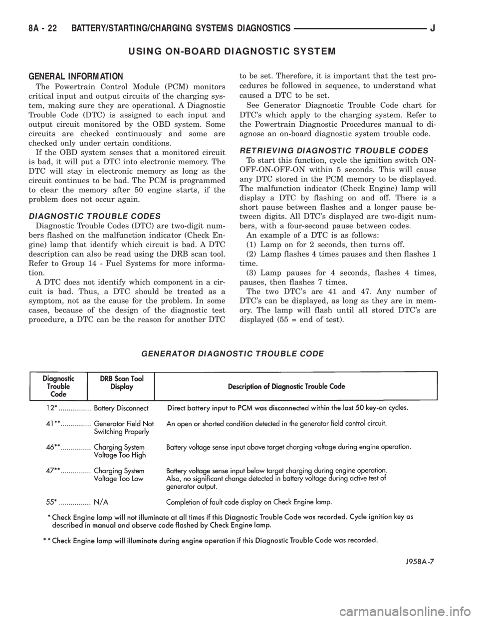
See Generator Diagnostic Trouble Code chart for
DTC's which apply to the charging system. Refer to
the Powertrain Diagnostic Procedures manual to di-
agnose an on-board diagnostic system trouble code.
RETRIEVING DIAGNOSTIC TROUBLE CODES
To start this function, cycle the ignition switch ON-
OFF-ON-OFF-ON within 5 seconds. This will cause
any DTC stored in the PCM memory to be displayed.
The malfunction indicator (Check Engine) lamp will
display a DTC by flashing on and off. There is a
short pause between flashes and a longer pause be-
tween digits. All DTC's displayed are two-digit num-
bers, with a four-second pause between codes.
An example of a DTC is as follows:
(1) Lamp on for 2 seconds, then turns off.
(2) Lamp flashes 4 times pauses and then flashes 1
time.
(3) Lamp pauses for 4 seconds, flashes 4 times,
pauses, then flashes 7 times.
The two DTC's are 41 and 47. Any number of
DTC's can be displayed, as long as they are in mem-
ory. The lamp will flash until all stored DTC's are
displayed (55 = end of test).
GENERATOR DIAGNOSTIC TROUBLE CODE
8A - 22 BATTERY/STARTING/CHARGING SYSTEMS DIAGNOSTICSJ
Page 312 of 2158
CAUTION: Be certain that battery cables are con-
nected to the correct battery terminals. Reverse po-
larity can damage electrical components.
(12) Place oiled felt washer on battery positive ter-
minal post.
(13) Install and tighten battery positive cable ter-
minal clamp. Then install and tighten negative cableterminal clamp. Both cable clamp bolts require
torque of 8.5 Nzm (75 in. lbs.).
(14) Apply a thin coating of petroleum jelly or
chassis grease to cable terminals and battery posts.
STARTER AND STARTER RELAY
GENERAL INFORMATION
This section covers starter and starter relay service
procedures only. For diagnostic procedures, refer to
Group 8A - Battery/Starting/Charging Systems Diag-
nostics. Service procedures for other starting system
components can be found as follows:
²battery - see Battery, in this group
²ignition switch - refer to Group 8D - Ignition Sys-
tems
²park/neutral position switch (automatic transmis-
sion) - refer to Group 21 - Transmission and Transfer
Case
²wiring harness and connectors - refer to Group 8W
- Wiring Diagrams.
STARTER
The starter motor incorporates several features to
create a reliable, efficient, compact and lightweight
unit. A planetary gear system (intermediate trans-
mission) is used between the electric motor and pin-
ion gear. This feature makes it possible to reduce the
dimensions of the starter. At the same time, it allows
higher armature rotational speed and delivers in-
creased torque through the pinion gear to the fly-
wheel or drive plate ring gear.
The use of a permanent magnet field also reduces
starter size and weight. This field consists of six
high-strength permanent magnets. The magnets are
aligned according to their polarity and are perma-
nently fixed in the starter field frame.
The starter motors for all engines are activated by
a solenoid mounted to the overrunning clutch hous-
ing. However, the starter motor/solenoid are serviced
only as a complete assembly. If either component
fails, the entire assembly must be replaced.
This unit is highly sensitive to hammering, shocks
and external pressure.
CAUTION: The starter motor MUST NOT BE
CLAMPED in a vise by the starter field frame. Doing
so may damage the magnets. It may be clamped by
the mounting flange ONLY.CAUTION: Do not connect starter motor incorrectly
when tests are being performed. The permanent
magnets may be damaged and rendered unservice-
able.
STARTER RELAY
The starter relay is an International Standards Or-
ganization (ISO) type relay, and is located in the
Power Distribution Center (PDC). Refer to underside
of PDC cover for relay location.
STARTER REMOVE/INSTALLÐ2.5L
XJ MODELS
(1) Disconnect battery negative cable.
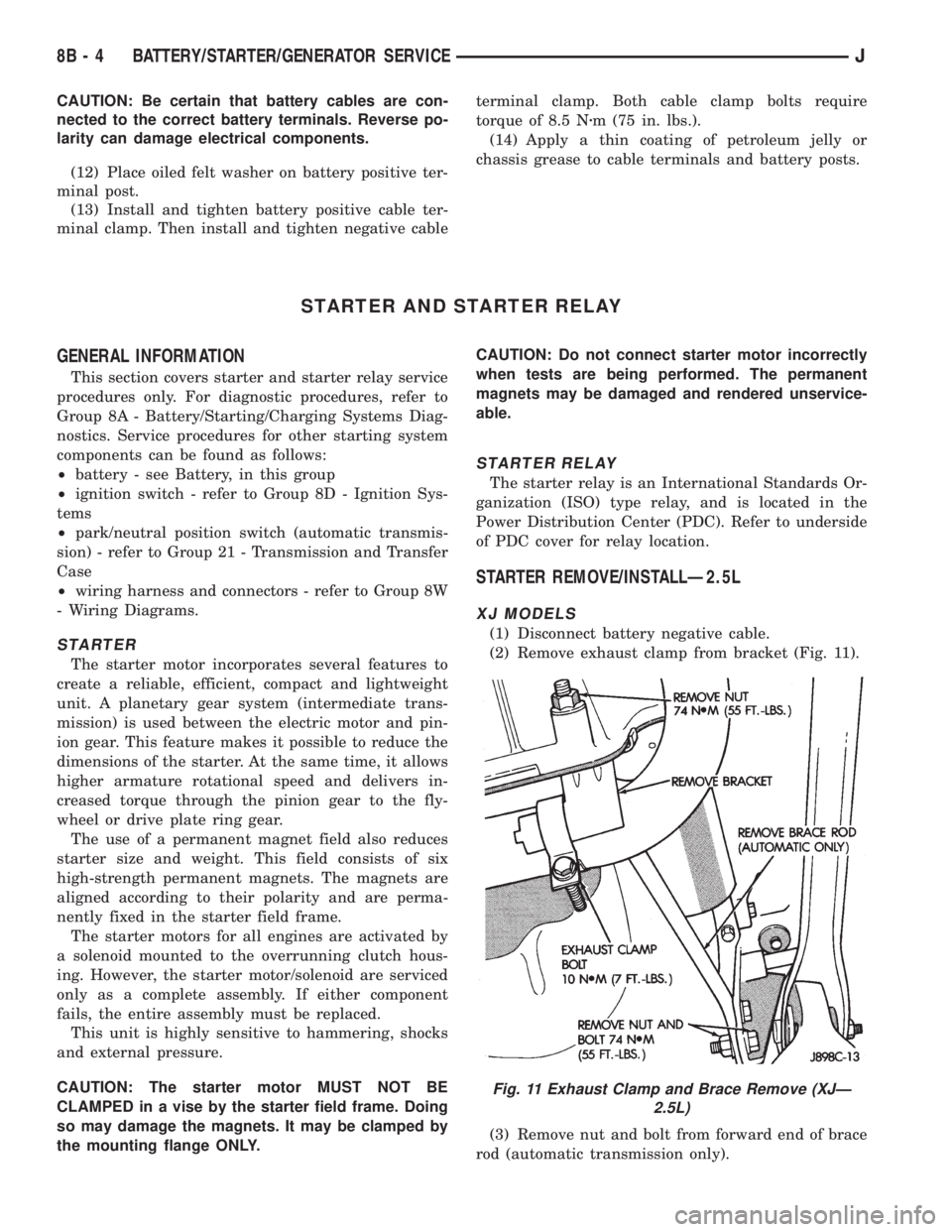
(2) Remove exhaust clamp from bracket (Fig. 11).
(3) Remove nut and bolt from forward end of brace
rod (automatic transmission only).
Fig. 11 Exhaust Clamp and Brace Remove (XJÐ
2.5L)
8B - 4 BATTERY/STARTER/GENERATOR SERVICEJ
Page 314 of 2158
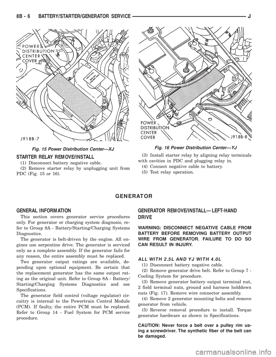
STARTER RELAY REMOVE/INSTALL
(1) Disconnect battery negative cable.
(2) Remove starter relay by unplugging unit from
PDC (Fig. 15 or 16).(3) Install starter relay by aligning relay terminals
with cavities in PDC and plugging relay in.
(4) Connect negative cable to battery.
(5) Test relay operation.
GENERATOR
GENERAL INFORMATION
This section covers generator service procedures
only. For generator or charging system diagnosis, re-
fer to Group 8A - Battery/Starting/Charging Systems
Diagnostics.
The generator is belt-driven by the engine. All en-
gines use serpentine drive. The generator is serviced
only as a complete assembly. If the generator fails for
any reason, the entire assembly must be replaced.
Two generator output ratings are available, de-
pending upon optional equipment. Be certain that
the replacement generator has the same output rat-
ing as the original unit. Refer to Group 8A - Battery/
Starting/Charging Systems Diagnostics and see
Specifications.
The generator field control (voltage regulator) cir-
cuitry is internal to the Powertrain Control Module
(PCM). If faulty, the entire PCM must be replaced.
Refer to Group 14 - Fuel System for PCM service
procedure.
GENERATOR REMOVE/INSTALLÐLEFT-HAND
DRIVE
WARNING: DISCONNECT NEGATIVE CABLE FROM
BATTERY BEFORE REMOVING BATTERY OUTPUT
WIRE FROM GENERATOR. FAILURE TO DO SO
CAN RESULT IN INJURY.
ALL WITH 2.5L AND YJ WITH 4.0L
(1) Disconnect battery negative cable.
(2) Remove generator drive belt. Refer to Group 7 -
Cooling System for procedure.
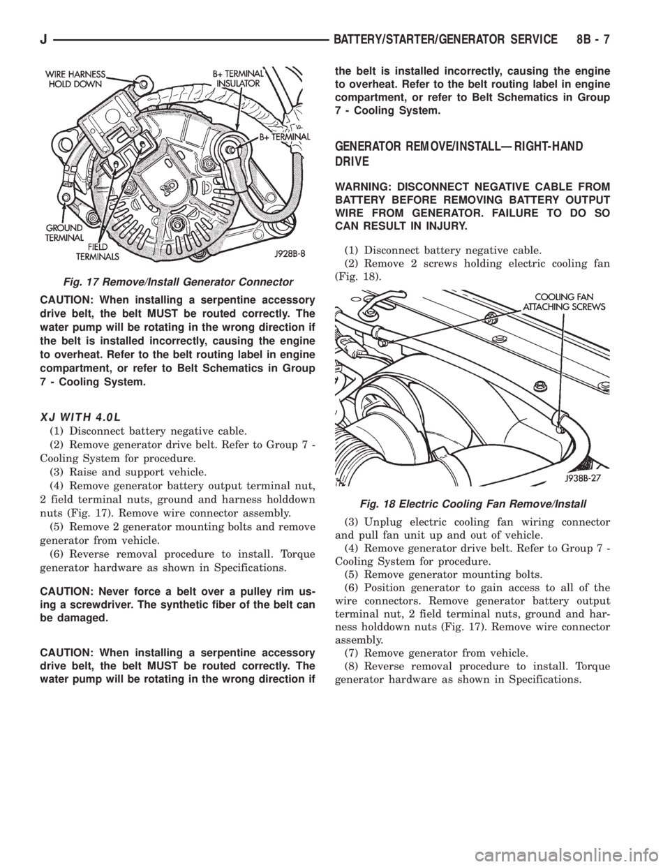
(3) Remove generator battery output terminal nut,
2 field terminal nuts, ground and harness holddown
nuts (Fig. 17). Remove wire connector assembly.
(4) Remove 2 generator mounting bolts and remove
generator from vehicle.
(5) Reverse removal procedure to install. Torque
generator hardware as shown in Specifications.
CAUTION: Never force a belt over a pulley rim us-
ing a screwdriver. The synthetic fiber of the belt can
be damaged.
Fig. 15 Power Distribution CenterÐXJFig. 16 Power Distribution CenterÐYJ
8B - 6 BATTERY/STARTER/GENERATOR SERVICEJ
Page 315 of 2158
CAUTION: When installing a serpentine accessory
drive belt, the belt MUST be routed correctly. The
water pump will be rotating in the wrong direction if
the belt is installed incorrectly, causing the engine
to overheat. Refer to the belt routing label in engine
compartment, or refer to Belt Schematics in Group
7 - Cooling System.
XJ WITH 4.0L
(1) Disconnect battery negative cable.
(2) Remove generator drive belt. Refer to Group 7 -
Cooling System for procedure.
(3) Raise and support vehicle.
(4) Remove generator battery output terminal nut,
2 field terminal nuts, ground and harness holddown
nuts (Fig. 17). Remove wire connector assembly.
(5) Remove 2 generator mounting bolts and remove
generator from vehicle.
(6) Reverse removal procedure to install. Torque
generator hardware as shown in Specifications.
CAUTION: Never force a belt over a pulley rim us-
ing a screwdriver. The synthetic fiber of the belt can
be damaged.
CAUTION: When installing a serpentine accessory
drive belt, the belt MUST be routed correctly. The
water pump will be rotating in the wrong direction ifthe belt is installed incorrectly, causing the engine
to overheat. Refer to the belt routing label in engine
compartment, or refer to Belt Schematics in Group
7 - Cooling System.
GENERATOR REMOVE/INSTALLÐRIGHT-HAND
DRIVE
WARNING: DISCONNECT NEGATIVE CABLE FROM
BATTERY BEFORE REMOVING BATTERY OUTPUT
WIRE FROM GENERATOR. FAILURE TO DO SO
CAN RESULT IN INJURY.
(1) Disconnect battery negative cable.
(2) Remove 2 screws holding electric cooling fan
(Fig. 18).
(3) Unplug electric cooling fan wiring connector
and pull fan unit up and out of vehicle.
(4) Remove generator drive belt. Refer to Group 7 -
Cooling System for procedure.
(5) Remove generator mounting bolts.
(6) Position generator to gain access to all of the
wire connectors. Remove generator battery output
terminal nut, 2 field terminal nuts, ground and har-
ness holddown nuts (Fig. 17). Remove wire connector
assembly.
(7) Remove generator from vehicle.
(8) Reverse removal procedure to install. Torque
generator hardware as shown in Specifications.
Fig. 17 Remove/Install Generator Connector
Fig. 18 Electric Cooling Fan Remove/Install
JBATTERY/STARTER/GENERATOR SERVICE 8B - 7
Page 321 of 2158
SERVICE PROCEDURES
COMPASS VARIATION ADJUSTMENT
Variance is the difference between magnetic north
and geographic north. In some areas, the difference
between magnetic and geographic north is great
enough to cause the compass to give false readings. If
this occurs, the variance must be set.
To set the variance:
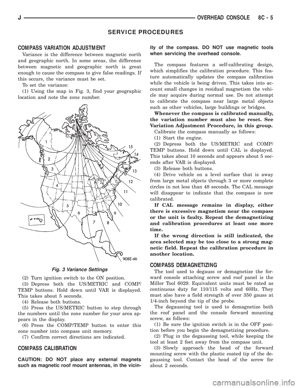
(1) Using the map in Fig. 3, find your geographic
location and note the zone number.
(2) Turn ignition switch to the ON position.
(3) Depress both the US/METRIC and COMP/
TEMP buttons. Hold down until VAR is displayed.
This takes about 5 seconds.
(4) Release both buttons.
(5) Press the US/METRIC button to step through
the numbers until the zone number for your area ap-
pears in the display.
(6) Press the COMP/TEMP button to enter this
zone number into compass unit memory.
(7) Confirm correct directions are indicated.
COMPASS CALIBRATION
CAUTION: DO NOT place any external magnets
such as magnetic roof mount antennas, in the vicin-ity of the compass. DO NOT use magnetic tools
when servicing the overhead console.
The compass features a self-calibrating design,
which simplifies the calibration procedure. This fea-
ture automatically updates the compass calibration
while the vehicle is being driven. This takes into ac-
count small changes in residual magnetism the vehi-
cle may acquire during normal use. Do not attempt
to calibrate the compass near large metal objects
such as other vehicles, large buildings or bridges.
Whenever the compass is calibrated manually,
the variation number must also be reset. See
Variation Adjustment Procedure, in this group.
Calibrate the compass manually as follows:
(1) Start the engine.
(2) Depress both the US/METRIC and COMP/
TEMP buttons. Hold down until CAL is displayed.
This takes about 10 seconds and appears about 5 sec-
onds after VAR is displayed.
(3) Release both buttons.
(4) Drive vehicle on a level surface that is away
from large metal objects through 3 or more complete
circles in not less than 48 seconds. The CAL message
will disappear to indicate that the compass is now
calibrated.
If CAL message remains in display, either
there is excessive magnetism near the compass
or the unit is faulty. Repeat the demagnetizing
and calibration procedures at least one more
time.
If the wrong direction is still indicated, the
area selected may be too close to a strong mag-
netic field. Repeat the calibration procedure in
another location.
COMPASS DEMAGNETIZING
The tool used to degauss or demagnetize the for-
ward console attaching screw and roof panel is the
Miller Tool 6029. Equivalent units must be rated as
continuous duty for 110/115 volts and 60Hz. They
must also have a field strength of over 350 gauss at
1/4-inch beyond the tip of the probe.
The degaussing tool is used to demagnetize both
the roof panel and the console forward mounting
screw, as follows:
(1) Be sure the ignition switch is in the OFF posi-
tion before you begin the demagnetizing procedure.
(2) Plug in the degaussing tool, while keeping the
tool at least 2 feet away from the compass unit.
(3) Slowly approach the head of the forward
mounting screw with the plastic coated tip of the de-
gaussing tool. Contact the head of the screw for
about 2 seconds.Fig. 3 Variance Settings
JOVERHEAD CONSOLE 8C - 5
Page 325 of 2158

IGNITION SYSTEMS
CONTENTS
page page
COMPONENT IDENTIFICATION/SYSTEM
OPERATION........................... 1
COMPONENT REMOVAL/INSTALLATION...... 17
DIAGNOSTICS/SERVICE PROCEDURES....... 6IGNITION SWITCHÐXJ MODELS........... 26
IGNITION SWITCHÐYJ MODELS........... 29
SPECIFICATIONS........................ 32
COMPONENT IDENTIFICATION/SYSTEM OPERATION
INDEX
page page
Automatic Shutdown (ASD) Relay.............. 1
Camshaft Position Sensor.................... 2
Crankshaft Position Sensor................... 3
Distributors............................... 4
Engine Coolant Temperature Sensor............ 5
General Information........................ 1Ignition Coil.............................. 4
Intake Manifold Air Temperature Sensor.......... 5
Manifold Absolute Pressure (MAP) Sensor........ 5
Oxygen (O2S) Sensor....................... 5
Powertrain Control Module (PCM).............. 5
Throttle Position Sensor..................... 5
GENERAL INFORMATION
Throughout this group, references are made to par-
ticular vehicle models by alphabetical designation
(XJ or YJ) or by the particular vehicle nameplate. A
chart showing a breakdown of alphabetical designa-
tions is included in the Introduction group at the be-
ginning of this manual.
This section of the group, Component Identifica-
tion/System Operation, will discuss ignition system
operation and will identify ignition system compo-
nents.
For diagnostic procedures and adjustments, refer to
the Diagnostics/Service Procedures section of this
group.
For removal and installation of ignition system
components, refer to the Component Removal/Instal-
lation section of this group.
For other useful information, refer to On-Board Di-
agnostics in the General Diagnosis sections of Group
14, Fuel System in this manual.
For operation of the DRB Scan Tool, refer to the
appropriate Powertrain Diagnostic Procedures ser-
vice manual.
An Ignition specifications section is included at the
end of this group. A general Maintenance Schedule
(mileage intervals) for ignition related items can be
found in Group 0, Lubrication and Maintenance. This
schedule can also be found in the Owners Manual.
IGNITION SYSTEMS
A multi-port, fuel injected engine is used on all
models. The ignition system is controlled by the pow-
ertrain control module (PCM) on all engines. The
PCM was formerly referred to as the SBEC or engine
controller.
The ignition system consists of:
²Spark plugs
²Ignition coil
²Secondary ignition cables
²Distributor (contains rotor and camshaft position
sensor)
²Powertrain control module (PCM)
²Crankshaft position sensor
AUTOMATIC SHUTDOWN (ASD) RELAY
The automatic shutdown (ASD) relay is located in
the power distribution center (PDC) near the battery
(Fig. 1 or 2). As one of its functions, it will supply
battery voltage to the ignition coil.
The ground circuit for the ASD relay is controlled
by the powertrain control module (PCM). This is
done through pin/cavity number 51 of the PCM 60-
way connector. The PCM then regulates ASD relay
operation by switching this ground circuit on-and-off.
Also refer to Ignition Coil for additional informa-
tion.
JIGNITION SYSTEMS 8D - 1