1995 JEEP XJ engine
[x] Cancel search: enginePage 48 of 2158
hose unless the caliper must also be removed
for maintenance.Support the caliper with a
hanger to prevent brake fluid hose damage.
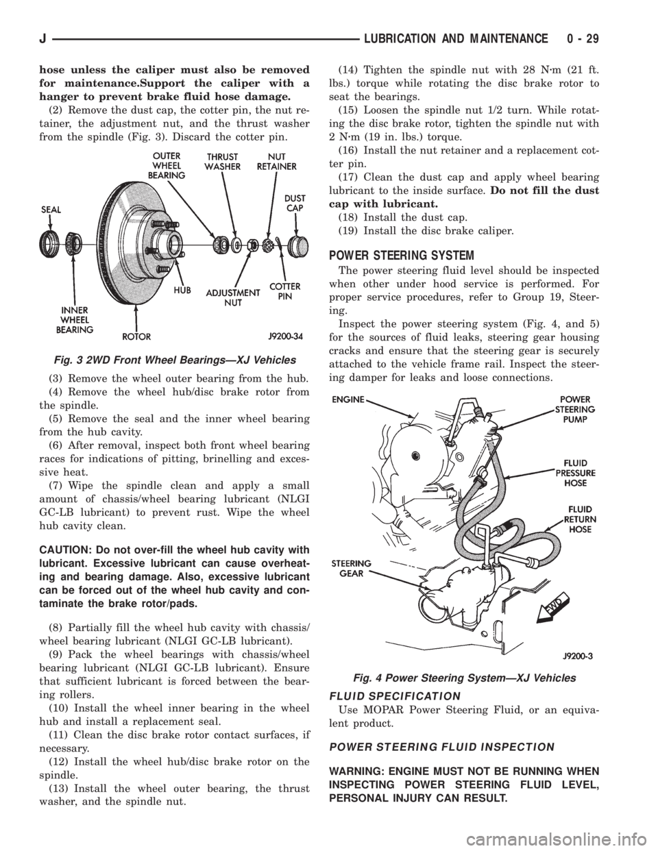
(2) Remove the dust cap, the cotter pin, the nut re-
tainer, the adjustment nut, and the thrust washer
from the spindle (Fig. 3). Discard the cotter pin.
(3) Remove the wheel outer bearing from the hub.
(4) Remove the wheel hub/disc brake rotor from
the spindle.
(5) Remove the seal and the inner wheel bearing
from the hub cavity.
(6) After removal, inspect both front wheel bearing
races for indications of pitting, brinelling and exces-
sive heat.
(7) Wipe the spindle clean and apply a small
amount of chassis/wheel bearing lubricant (NLGI
GC-LB lubricant) to prevent rust. Wipe the wheel
hub cavity clean.
CAUTION: Do not over-fill the wheel hub cavity with
lubricant. Excessive lubricant can cause overheat-
ing and bearing damage. Also, excessive lubricant
can be forced out of the wheel hub cavity and con-
taminate the brake rotor/pads.
(8) Partially fill the wheel hub cavity with chassis/
wheel bearing lubricant (NLGI GC-LB lubricant).
(9) Pack the wheel bearings with chassis/wheel
bearing lubricant (NLGI GC-LB lubricant). Ensure
that sufficient lubricant is forced between the bear-
ing rollers.
(10) Install the wheel inner bearing in the wheel
hub and install a replacement seal.
(11) Clean the disc brake rotor contact surfaces, if
necessary.
(12) Install the wheel hub/disc brake rotor on the
spindle.
(13) Install the wheel outer bearing, the thrust
washer, and the spindle nut.(14) Tighten the spindle nut with 28 Nzm (21 ft.
lbs.) torque while rotating the disc brake rotor to
seat the bearings.
(15) Loosen the spindle nut 1/2 turn. While rotat-
ing the disc brake rotor, tighten the spindle nut with
2Nzm (19 in. lbs.) torque.
(16) Install the nut retainer and a replacement cot-
ter pin.
(17) Clean the dust cap and apply wheel bearing
lubricant to the inside surface.Do not fill the dust
cap with lubricant.
(18) Install the dust cap.
(19) Install the disc brake caliper.
POWER STEERING SYSTEM
The power steering fluid level should be inspected
when other under hood service is performed. For
proper service procedures, refer to Group 19, Steer-
ing.
Inspect the power steering system (Fig. 4, and 5)
for the sources of fluid leaks, steering gear housing
cracks and ensure that the steering gear is securely
attached to the vehicle frame rail. Inspect the steer-
ing damper for leaks and loose connections.
FLUID SPECIFICATION
Use MOPAR Power Steering Fluid, or an equiva-
lent product.
POWER STEERING FLUID INSPECTION
WARNING: ENGINE MUST NOT BE RUNNING WHEN
INSPECTING POWER STEERING FLUID LEVEL,
PERSONAL INJURY CAN RESULT.
Fig. 3 2WD Front Wheel BearingsÐXJ Vehicles
Fig. 4 Power Steering SystemÐXJ Vehicles
JLUBRICATION AND MAINTENANCE 0 - 29
Page 49 of 2158

FLUID LEVEL
The fluid level indicator (dipstick) is attached to
the reservoir cap (Fig. 6). The fluid level in the res-
ervoir can be determined with the fluid either hot or
cold.
(1) Remove the cap from the reservoir.
(2) Depending on fluid temperature, if the level is
below the FULL HOT mark or the FULL COLD
mark on the dipstick, add power steering fluid.
(3) Install the cap on the reservoir.CAUTION: Do not over fill power steering reservoir
when adding fluid, seal damage and leakage can re-
sult.
MANUAL STEERING GEAR
The manual steering gear should be inspected for
damage at the same time as the engine oil is
changed and the oil filter is replaced. Refer to Group
19, Steering for additional information and service
procedures.
POWER BRAKE SYSTEM
RECOMMENDED MAINTENANCE
The brake fluid level (Fig. 8) should be inspected
when other underhood service is done. With disc-
brakes, the fluid level can be expected to fall as the
brake pads wear. However, a low fluid level can also
be caused by a leak, and repair will then be neces-
sary. Refer to Group 5, Brakes for proper service pro-
cedures.
In addition, the brake system should be operation-
ally tested periodically to ensure that it is function-
ing normally.
FLUID SPECIFICATION
Jeep power brake systems require MOPAR Heavy-
Duty Brake Fluid, or an equivalent product identified
as conforming to FMVSS No. 116, DOT-3 and SAE
J-1703 specifications.
Use brake fluid from properly sealed container
when adding fluid to the reservoir. Never use re-
claimed fluid or fluid that does not conform to the
DOT/SAE Standards.
CAUTION: Use of a brake fluid that has a lower ini-
tial boiling point then specified by FMVSS No. 116,
DOT 3 and SAE J-1703 could result in sudden brake
failure during hard, prolonged braking.
Do not allow petroleum base fluids to contaminate
the brake fluid. Seal damage will result.
BRAKE FLUID LEVEL
STANDARD POWER BRAKE SYSTEM
(1) Clean the cover and the sides of the brake fluid
reservoir.
(2) Detach the bail retainer from the reservoir
cover and remove the cover from the reservoir.
(3) The brake fluid level should be 6 mm (1/4 in)
below the rim of each reservoir well for XJ and YJ
Vehicles (Fig. 7 and 8). If not, add brake fluid as nec-
essary.
(4) Inspect the reservoir cover bail retainer for ten-
sion and the cover for proper fit. The cover should fit
tight and have a good seal.
Fig. 5 Power Steering SystemÐYJ Vehicles
Fig. 6 Power Steering Fluid Reservoir DipstickÐ
Typical
0 - 30 LUBRICATION AND MAINTENANCEJ
Page 50 of 2158

(5) Inspect the reservoir rubber diaphragm seal for
cracks, cuts and distortion.
(6) Inspect the brake fluid tubing fittings and the
master cylinder housing for indications of fluid leak-
age. Repair as necessary.
(7) Install the brake fluid reservoir cover.
ANTI-LOCK BRAKE SYSTEMÐXJ VEHICLES
The anti-lock brake system fluid reservoir for XJ
Vehicles is located in the engine compartment at the
left side of the dash panel.
(1) Turn the ignition switch ON and allow the
pump motor to operate until it automatically de-en-
ergizes.
(2) Clean the cover before removing it.
CAUTION: Over-filling could cause fluid overflow
and possible reservoir damage when the pump mo-
tor energizes.
(3) The brake fluid level should be no lower than
the ADD indicator on the side of the reservoir (Fig.
8). If not, add brake fluid as necessary. Raise the
fluid level to the FULL indicator only. Do not over-fill
the reservoir.
(4) Turn the ignition switch OFF.
BRAKE SYSTEM INSPECTION
A brake system inspection should be included with
all brake service procedures, and also each time the
vehicle is lubricated.
(1) Inspect the brake pads and linings for excessive
wear, cracks, charred surfaces and broken rivets.
(2) Inspect brake pads and linings for contamina-
tion from brake fluid, and/or other fluids.
(3) Replace the brake pads linings if they are worn
to within 0.78 mm (1/32 in) of the rivet head.
(4) Operate the rear brake self-adjuster lever and
pivot. Test the operation of the self-adjuster screw for
ease of movement.
(5) Inspect the self-adjuster components for wear
or damage.
(6) Inspect the disc brake caliper dust boot for
damage and indications of brake fluid leakage. In-
spect the bushings and pins for corrosion, tears and a
binding condition.
(7) Pull the rear wheel cylinder dust boot back to
expose the wheel cylinder housing. Inspect for fluid
leaks. Inspect the pistons and cylinder bores.
(8) Inspect the brake differential warning valve
and housing for indications of leakage.
BRAKE FLUID HOSES/TUBING
The rubber brake fluid hoses should be inspected
for:
²Correct length
²Severe surface cracking
²Swelling
²Pulling
²Scuffing
²Excessively worn areas
If the hose has cracks or abrasions in the rub-
ber cover, the hose should be replaced.
(1) Inspect all the hoses for kinks, a distorted con-
dition and fluid leakage.
(2) Inspect the hose and tubing routing under the
vehicle. Verify that no hose/tubing is rubbing against
any exhaust or other underbody components.
PARKING BRAKE
(1) Engage the parking brake pedal and then re-
lease it.
(2) Test it for smooth operation and vehicle-holding
capability.
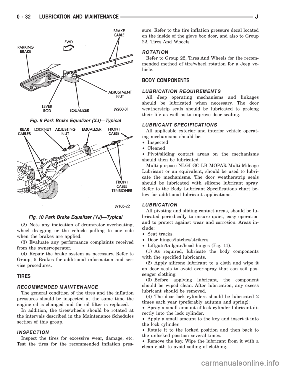
(3) Inspect the parking brake cables.
(4) With the parking brake released, the rear
wheels should
rotate without restriction. Adjust the parking brake
cable tension, if necessary (Fig. 9 and 10).
(5) Repair any parking brake malfunctions.
BRAKE OPERATIONAL TEST
(1) Drive the vehicle and test for proper brake ac-
tion.
Fig. 7 Reservoir Fluid LevelÐYJ (2.5L)
Fig. 8 Reservoir Fluid LevelÐYJ-XJ and Anti-Lock
Brake System
JLUBRICATION AND MAINTENANCE 0 - 31
Page 51 of 2158
(2) Note any indication of drum/rotor overheating,
wheel dragging or the vehicle pulling to one side
when the brakes are applied.
(3) Evaluate any performance complaints received
from the owner/operator.
(4) Repair the brake system as necessary. Refer to
Group, 5 Brakes for additional information and ser-
vice procedures.
TIRES
RECOMMENDED MAINTENANCE
The general condition of the tires and the inflation
pressures should be inspected at the same time the
engine oil is changed and the oil filter is replaced.
In addition, the tires/wheels should be rotated at
the intervals described in the Maintenance Schedules
section of this group.
INSPECTION
Inspect the tires for excessive wear, damage, etc.
Test the tires for the recommended inflation pres-sure. Refer to the tire inflation pressure decal located
on the inside of the glove box door, and also to Group
22, Tires And Wheels.
ROTATION
Refer to Group 22, Tires And Wheels for the recom-
mended method of tire/wheel rotation for a Jeep ve-
hicle.
BODY COMPONENTS
LUBRICATION REQUIREMENTS
All Jeep operating mechanisms and linkages
should be lubricated when necessary. The door
weatherstrip seals should be lubricated to prolong
their life as well as to improve door sealing.
LUBRICANT SPECIFICATIONS
All applicable exterior and interior vehicle operat-
ing mechanisms should be:
²Inspected
²Cleaned
²Pivot/sliding contact areas on the mechanisms
should then be lubricated.
Multi-purpose NLGI GC-LB MOPAR Multi-Mileage
Lubricant or an equivalent, should be used to lubri-
cate the mechanisms. The door weatherstrip seals
should be lubricated with silicone lubricant spray.
Refer to the Body Lubricant Specifications chart be-
low for additional lubricant applications.
LUBRICATION
All pivoting and sliding contact areas, should be lu-
bricated periodically to ensure quiet, easy operation
and to protect against wear and corrosion. Areas in-
clude:
²Seat tracks.
²Door hinges/latches/strikers.
²Liftgate/tailgate/hood hinges (Fig. 11).
(1) As required, lubricate the body components
with the specified lubricants.
(2) Apply silicone lubricant to a cloth and wipe it
on door seals to avoid over-spray that can soil pas-
senger clothing.
(3) Before applying lubricant, the component
should be wiped clean. After lubrication, any excess
lubricant should be removed.
(4) The door lock cylinders should be lubricated 2
times each year (preferably autumn and spring):
²Spray a small amount of lock cylinder lubricant di-
rectly into the lock cylinder.
²Apply a small amount to the key and insert it into
the lock cylinder.
²Rotate it to the locked position and then back to
the unlocked position several times.
²Remove the key. Wipe the lubricant from it with a
clean cloth to avoid soiling of clothing.
Fig. 9 Park Brake Equalizer (XJ)ÐTypical
Fig. 10 Park Brake Equalizer (YJ)ÐTypical
0 - 32 LUBRICATION AND MAINTENANCEJ
Page 60 of 2158
ALIGNMENT MEASUREMENTS AND ADJUSTMENTS
Before each alignment reading, the vehicle should
be jounced (rear first, then front). Grasp each
bumper at the center and jounce the vehicle up and
down several times. Always release the bumper in
the down position.Set the front end alignment to
specifications with the vehicle at its NOR-
MALLY RIDE HEIGHT.
CAMBER
The wheel camber angle is preset. This angle is not
adjustable and cannot be altered.
CASTER
Before checking the caster of the front axle for cor-
rect angle, be sure the axle is not bent or twisted.
Road test the vehicle, make left and right turns. If
the steering wheel returns to the center position un-
assisted, the caster angle is correct. If steering wheeldoes not return toward the center position unas-
sisted, an incorrect caster angle is probable.
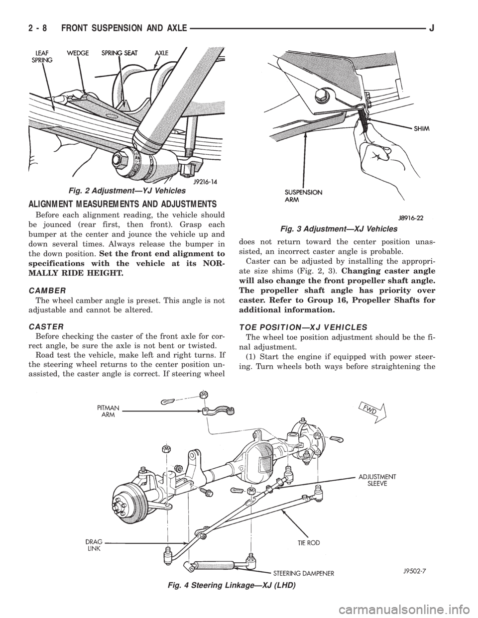
Caster can be adjusted by installing the appropri-
ate size shims (Fig. 2, 3).Changing caster angle
will also change the front propeller shaft angle.
The propeller shaft angle has priority over
caster. Refer to Group 16, Propeller Shafts for
additional information.
TOE POSITIONÐXJ VEHICLES
The wheel toe position adjustment should be the fi-
nal adjustment.
(1) Start the engine if equipped with power steer-
ing. Turn wheels both ways before straightening the
Fig. 2 AdjustmentÐYJ Vehicles
Fig. 3 AdjustmentÐXJ Vehicles
Fig. 4 Steering LinkageÐXJ (LHD)
2 - 8 FRONT SUSPENSION AND AXLEJ
Page 61 of 2158
wheels. Secure the steering wheel with the front
wheels in the straight-ahead position. Turn off the
engine.
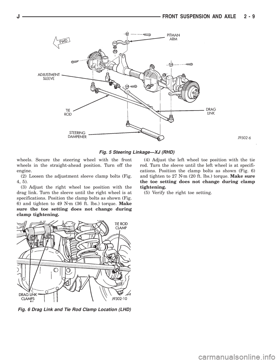
(2) Loosen the adjustment sleeve clamp bolts (Fig.
4, 5).
(3) Adjust the right wheel toe position with the
drag link. Turn the sleeve until the right wheel is at
specifications. Position the clamp bolts as shown (Fig.
6) and tighten to 49 Nzm (36 ft. lbs.) torque.Make
sure the toe setting does not change during
clamp tightening.(4) Adjust the left wheel toe position with the tie
rod. Turn the sleeve until the left wheel is at specifi-
cations. Position the clamp bolts as shown (Fig. 6)
and tighten to 27 Nzm (20 ft. lbs.) torque.Make sure
the toe setting does not change during clamp
tightening.
(5) Verify the right toe setting.
Fig. 5 Steering LinkageÐXJ (RHD)
Fig. 6 Drag Link and Tie Rod Clamp Location (LHD)
JFRONT SUSPENSION AND AXLE 2 - 9
Page 62 of 2158
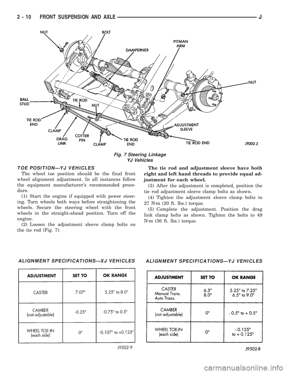
TOE POSITIONÐYJ VEHICLES
The wheel toe position should be the final front
wheel alignment adjustment. In all instances follow
the equipment manufacturer's recommended proce-
dure.
(1) Start the engine if equipped with power steer-
ing. Turn wheels both ways before straightening the
wheels. Secure the steering wheel with the front
wheels in the straight-ahead position. Turn off the
engine.
(2) Loosen the adjustment sleeve clamp bolts on
the tie rod (Fig. 7).The tie rod and adjustment sleeve have both
right and left hand threads to provide equal ad-
justment for each wheel.
(3) After the adjustment is completed, position the
tie rod adjustment sleeve clamp bolts as shown.
(4) Tighten the adjustment sleeve clamp bolts to
27 Nzm (20 ft. lbs.) torque.
(5) Complete the adjustment. Position the drag
link clamp bolts as shown. Tighten the bolts to 49
Nzm (36 ft. lbs.) torque.
Fig. 7 Steering Linkage
YJ Vehicles
ALIGNMENT SPECIFICATIONSÐXJ VEHICLESALIGNMENT SPECIFICATIONSÐYJ VEHICLES
2 - 10 FRONT SUSPENSION AND AXLEJ
Page 65 of 2158
LOWER SUSPENSION ARM
REMOVAL
(1) Raise and support the vehicle.
(2) Remove the lower suspension arm nut and bolt
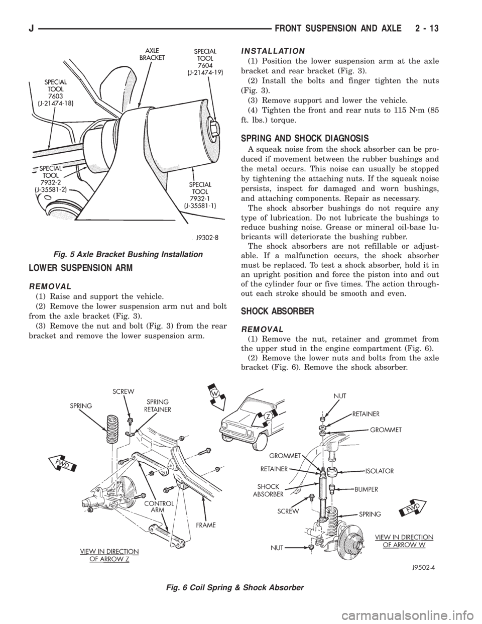
from the axle bracket (Fig. 3).
(3) Remove the nut and bolt (Fig. 3) from the rear
bracket and remove the lower suspension arm.
INSTALLATION
(1) Position the lower suspension arm at the axle
bracket and rear bracket (Fig. 3).
(2) Install the bolts and finger tighten the nuts
(Fig. 3).
(3) Remove support and lower the vehicle.
(4) Tighten the front and rear nuts to 115 Nzm (85
ft. lbs.) torque.
SPRING AND SHOCK DIAGNOSIS
A squeak noise from the shock absorber can be pro-
duced if movement between the rubber bushings and
the metal occurs. This noise can usually be stopped
by tightening the attaching nuts. If the squeak noise
persists, inspect for damaged and worn bushings,
and attaching components. Repair as necessary.
The shock absorber bushings do not require any
type of lubrication. Do not lubricate the bushings to
reduce bushing noise. Grease or mineral oil-base lu-
bricants will deteriorate the bushing rubber.
The shock absorbers are not refillable or adjust-
able. If a malfunction occurs, the shock absorber
must be replaced. To test a shock absorber, hold it in
an upright position and force the piston into and out
of the cylinder four or five times. The action through-
out each stroke should be smooth and even.
SHOCK ABSORBER
REMOVAL
(1) Remove the nut, retainer and grommet from
the upper stud in the engine compartment (Fig. 6).
(2) Remove the lower nuts and bolts from the axle
bracket (Fig. 6). Remove the shock absorber.
Fig. 6 Coil Spring & Shock Absorber
Fig. 5 Axle Bracket Bushing Installation
JFRONT SUSPENSION AND AXLE 2 - 13