1995 JEEP XJ engine
[x] Cancel search: enginePage 1071 of 2158
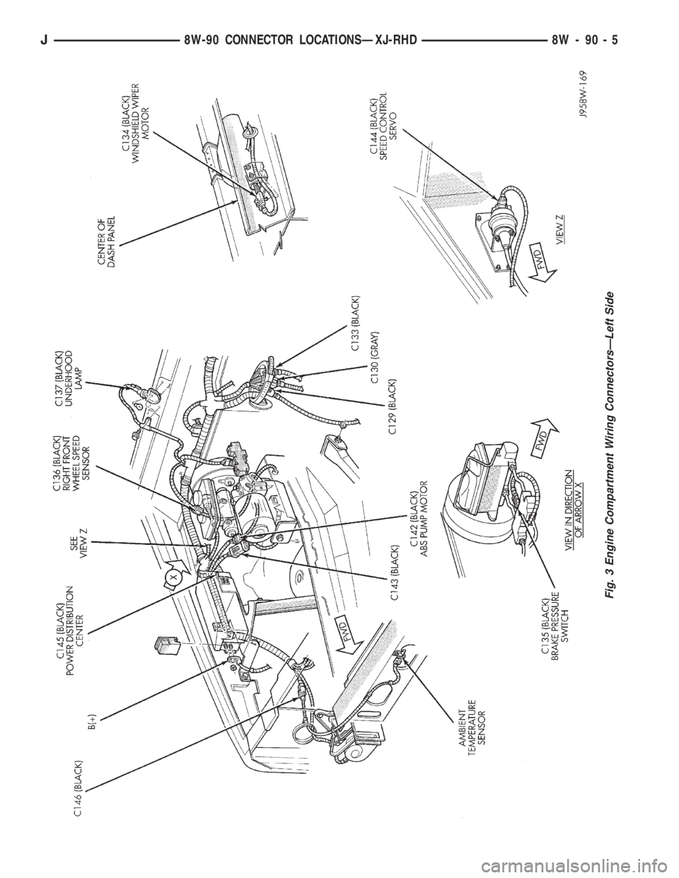
Fig. 3 Engine Compartment Wiring ConnectorsÐLeft Side
J8W-90 CONNECTOR LOCATIONSÐXJ-RHD 8W - 90 - 5
Page 1072 of 2158
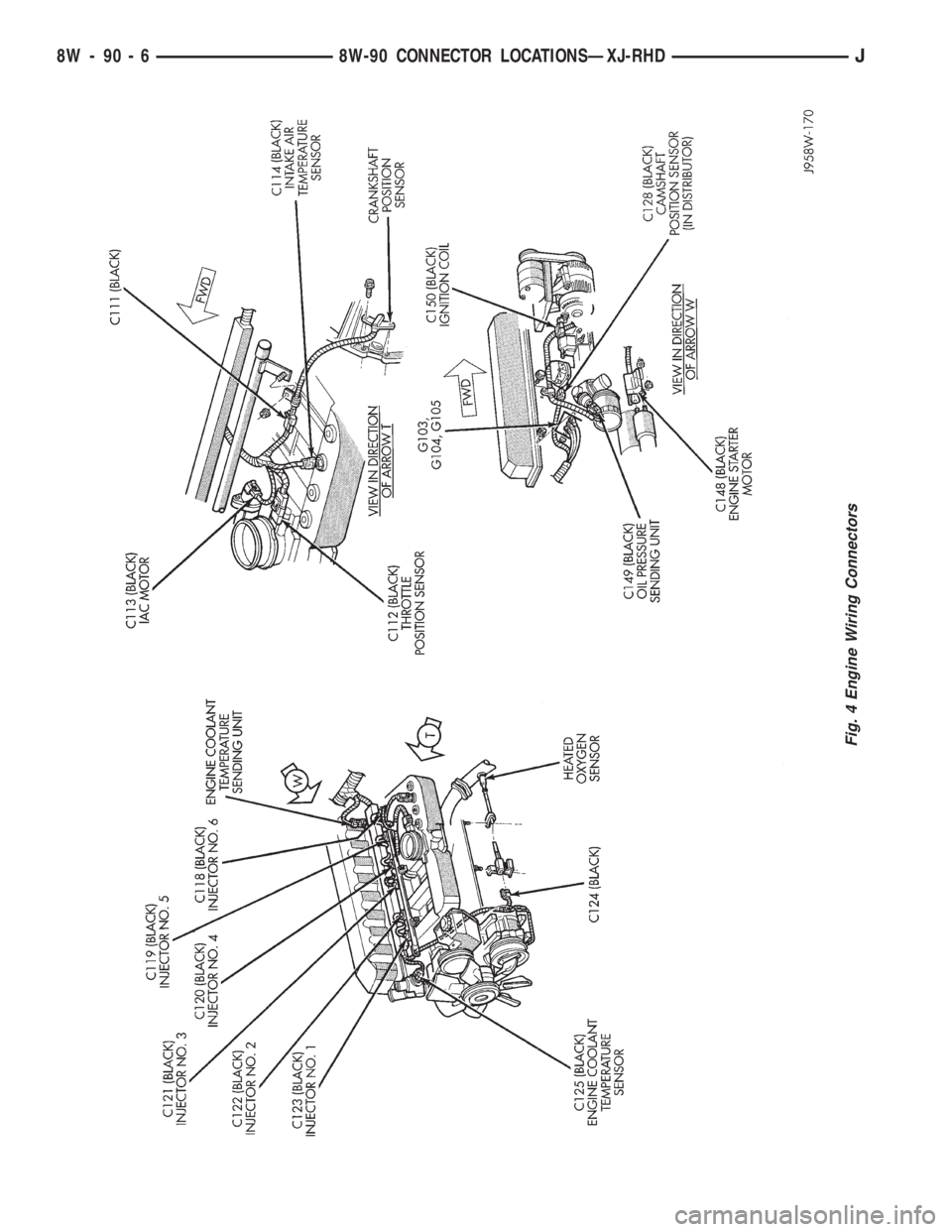
Fig. 4 Engine Wiring Connectors
8W - 90 - 6 8W-90 CONNECTOR LOCATIONSÐXJ-RHDJ
Page 1087 of 2158
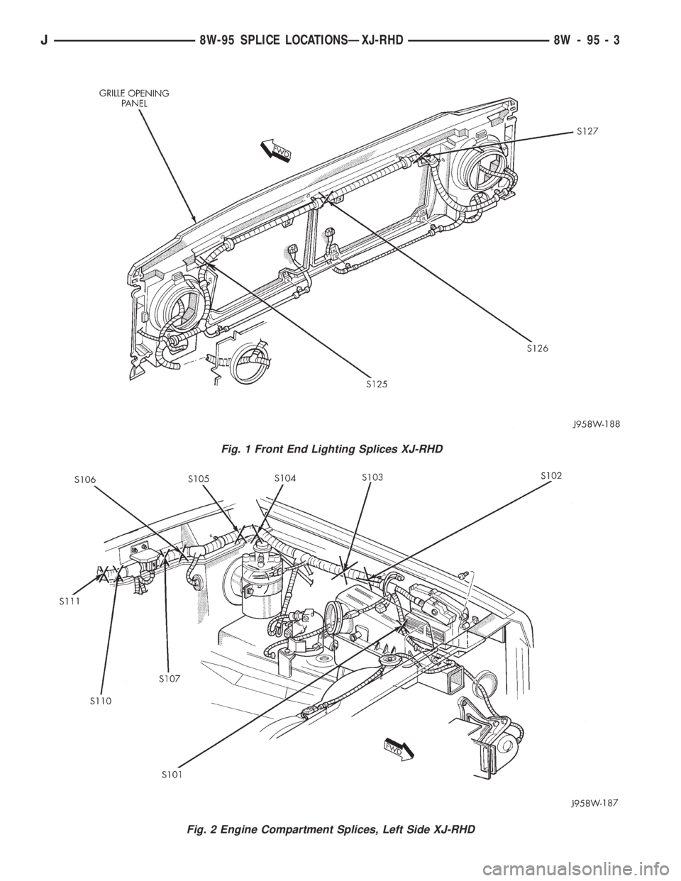
Fig. 1 Front End Lighting Splices XJ-RHD
Fig. 2 Engine Compartment Splices, Left Side XJ-RHD
J8W-95 SPLICE LOCATIONSÐXJ-RHD 8W - 95 - 3
Page 1088 of 2158
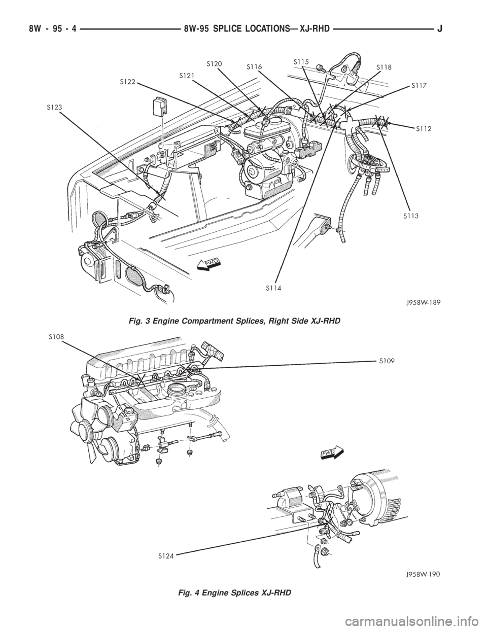
Fig. 3 Engine Compartment Splices, Right Side XJ-RHD
Fig. 4 Engine Splices XJ-RHD
8W - 95 - 4 8W-95 SPLICE LOCATIONSÐXJ-RHDJ
Page 1104 of 2158
POWER DISTRIBUTION
GENERAL INFORMATION
This section covers the Power Distribution Center
(PDC) and all circuits involved with it. For additional
information on system operation refer to the appro-
priate section of the wiring diagrams.
DIAGRAM INDEX
Component Page
A/C Compressor Clutch Relay..............8W-11-3, 10
ABS Pump Motor Relay..................8W-11-3, 9
ABS Control Module.....................8W-11-8, 9
ABS Power Relay......................8W-11-3, 8
Automatic Shut Down Relay................8W-11-3, 6
Engine Starter Motor Relay................8W-11-3, 4
Fuel Pump Relay.......................8W-11-3, 6
Fuse 1 (Fuse Block).......................8W-11-8
Fuse 1 (PDC)...........................8W-11-6
Fuse 2 (PDC)...........................8W-11-7
Fuse 3 (PDC)...........................8W-11-7
Fuse 4 (PDC)......................8W-11-4, 8, 10
Fuse 5 (Fuse Block).......................8W-11-6
Fuse 5 (PDC)...........................8W-11-7Component Page
Fuse 6 (PDC)...........................8W-11-7
Fuse 7 (PDC)...........................8W-11-7
Fuse 8 (PDC)...........................8W-11-5
Fuse 9 (Fuse Block)......................8W-11-10
Fuse 9 (PDC)...........................8W-11-9
Fuse 10 (PDC)..........................8W-11-8
Fuse 11 (PDC)..........................8W-11-5
Fuse 12 (Fuse Block)......................8W-11-8
Fuse 12 (PDC)..........................8W-11-5
Headlamp Switch.........................8W-11-7
Horn Relay...........................8W-11-3, 5
Ignition Switch......................8W-11-4, 8, 10
Power Distribution Center...................8W-11-2
Powertrain Control Module..............8W-11-4, 6, 10
J8W-11 POWER DISTRIBUTIONÐYJ VEHICLES 8W - 11 - 1
Page 1118 of 2158
CHARGING SYSTEM
CHARGING SYSTEM
The charging system is an integral part of the bat-
tery and starting systems. Because all these systems
work in conjunction, diagnose and test them together.
Circuit A11 connects to the generator output termi-
nal and splices to fuse 2 and fuse 6 in the Power Dis-
tribution Center (PDC). Circuit A0 connects the
battery to the PDC.
Circuit Z0 provides ground for the generator. Cir-
cuit Z0 attaches to the right side rear of the engine.
When the ignition switch is in either the START or
RUN position, it connects circuit A1 from fuse 4 in
the PDC to circuit A21. Circuit A21 powers fuse 5 in
the fuse block. Circuit G50 from fuse 5 splices to
power the coil side of the Automatic Shut Down
(ASD) relay. The Powertrain Control Module (PCM)
provides ground for the relay on circuit K51. Circuit
K51 connects to cavity 51 of the PCM.
When the PCM grounds the ASD relay, contacts in-
side the relay close and connect circuit A14 from fuse
1 in the PDC to circuit A142. Circuit A142 splices to
the generator field terminal.
The PCM has an internal voltage regulator that
controls generator output. The PCM controls the gen-
erator field on circuit K20. Circuit K20 connects to
PCM cavity 20.When the engine operates and there is current in
the generator field, the generator produces a B+ volt-
age. The generator supplies B+ voltage to the battery
through the A11 and A0 circuits.
HELPFUL INFORMATION
²The ignition switch also connects circuit A1 with
circuits A41, A22, and A31.
²Circuit A21 also powers fuse 9 in the fuse block.
²Circuit G50 also powers the coil sides of the fuel
pump relay and the torque convertor clutch (TCC) re-
lay.
²The ASD relay supplies battery voltage for the fuel
injectors, ignition coil, and the heated oxygen sensor.
²Circuit K51 also provides ground for the coil side
of the fuel pump relay.
DIAGRAM INDEX
Component Page
Battery...............................8W-20-2
Fuse 2 (PDC)...........................8W-20-2
Fuse 6 (PDC)...........................8W-20-2
Generator..............................8W-20-2
Powertrain Control Module (PCM)..............8W-20-2
J8W-20 CHARGING SYSTEMÐYJ VEHICLES 8W - 20 - 1
Page 1120 of 2158
STARTING SYSTEM
STARTING SYSTEM
AUTOMATIC TRANSMISSIONS
Circuit A0 from the battery is double crimped at
the positive battery post. One branch of circuit A0
(battery positive cable) connects to the engine starter
motor. The other A0 branch supplies voltage to the
bus bar in the Power Distribution Center (PDC).
The PDC supplies battery voltage to the engine
starter motor solenoid on circuit T40 when the coil
side of the engine starter motor relay energizes. Cir-
cuit A1 from the fuse 4 in the PDC supplies battery
voltage to the contact side of the starter motor relay.
The ignition switch supplies battery voltage to the
coil side of the starter motor relay on circuit A41
when the key is moved to the START position and
the Park/Neutral position switch is closed. Ground
for the coil side of the starter motor relay is supplied
by the case grounded Park/Neutral position switch.
Circuit T41 connects the coil side of the relay to the
Park/Neutral position switch.
When the starter motor relay energizes and the
contacts close, circuit T40 supplies battery voltage to
the starter motor solenoid. Circuit A0 from the bat-
tery supplies voltage to the starter motor when the
solenoid energizes.
MANUAL TRANSMISSIONS
Circuit A0 from the battery is double crimped at
the positive battery post. One branch of circuit A0
(battery positive cable) connects to the battery
starter motor. The other A0 branch supplies voltage
to the bus bar in the Power Distribution Center
(PDC).The PDC supplies battery voltage to the engine
starter motor solenoid on circuit T40 when the coil
side of the engine starter motor relay energizes. Cir-
cuit A1 from the fuse 4 in the PDC supplies battery
voltage to the contact side of the starter motor relay.
The ignition switch supplies battery voltage to the
coil side of the starter motor relay on circuit A41
when the key is moved to the START position. Cir-
cuit T41 from the coil side of the relay connects to a
Z2 jumper wire in the back-up lamp switch. Circuit
Z2 provides ground for the starter motor relay.
When the starter motor relay energizes and the
contacts close, circuit T40 supplies battery voltage to
the starter motor solenoid. Circuit A0 from the bat-
tery supplies voltage to the starter motor when the
solenoid energizes.
HELPFUL INFORMATION
²The Park/Neutral switch closes when the trans-
mission is in either the PARK or NEUTRAL posi-
tions.
²Circuit T41 also connects to cavity 30 of the Pow-
ertrain Control Module (PCM). This input tells the
PCM the operator is starting the vehicle.
DIAGRAM INDEX
Component Page
Engine Starter Motor......................8W-21-2
Engine Starter Motor Relay..................8W-21-2
Ignition Switch..........................8W-21-2
Park/Neutral Position Switch.................8W-21-2
Power Distribution Center (PDC)...............8W-21-2
Powertrain Control Module (PCM)..............8W-21-2
Fuse 4 (PDC)...........................8W-21-2
J8W-21 STARTING SYSTEMÐYJ VEHICLES 8W - 21 - 1
Page 1122 of 2158
FUEL/IGNITION
INDEX
page page
Automatic Shut Down (ASD) Relay............. 1
Battery Feed.............................. 2
Brake Switch Input......................... 5
Camshaft Position Sensor.................... 3
Crankshaft Position Sensor................... 3
Data Link Connector........................ 5
Diagram Index............................ 5
Engine Coolant Temperature Sensor............ 3
Fuel Injectors............................. 2
Fuel Pump Module......................... 2
Fuel Pump Relay.......................... 2
Heated Oxygen Sensor...................... 3Idle Air Control (IAC) Motor................... 2
Ignition Coil.............................. 2
Ignition Switch............................ 1
Intake Air Temperature Sensor................ 4
Malfunction Indicator Lamp (MIL)............... 5
Manifold Absolute Pressure Sensor............. 4
Park/Neutral Position Switch.................. 4
Power (Device) Ground...................... 5
Power Steering Pressure Switch............... 4
Tachometer Signal......................... 5
Throttle Position Sensor..................... 4
Vehicle Speed Sensor....................... 3
IGNITION SWITCH
Circuit A1 from fuse 4 in the Power Distribution
Center (PDC), supplies battery voltage to the ignition
switch. Depending upon position, the ignition switch
powers circuits A21, A22, A31, and A41.
START POSITION
In the START position, the ignition switch connects
circuit A1 to circuit A41. Circuit A41 connects to the
coil side of the starter motor relay.
Also in the START position, the case grounded ig-
nition switch provides ground for the brake lamp
switch and parking brake lamp switch on circuit G11.
START OR RUN POSITION
In the START and RUN position, the ignition
switch connects circuit A1 with circuit A21. The A21
circuit connects to fuses 5 and 9 in the fuse block.
Fuse 9 powers circuit G5. Fuse 5 powers circuit G50.
²Circuit G5 powers the buzzer module. Circuit G5
also splices to power the daytime running lamps
module (Canada only), A/C compressor clutch relay,
heated rear window relay, and the gauges and indi-
cator lamps in the instrument cluster.
RUN (ONLY) POSITION
When the ignition switch is in the RUN position, it
connects circuit A1 to circuit A22. Circuit A22 powers
fuses 1, 12, and 13 in the fuse block.
²Fuse 1 powers the rear wiper system on circuit
V23.
²Fuse 12 feeds the blower motor and air condition-
ing system on circuit C1.
²Fuse 13 feeds circuit F15 which powers the ABS
module and connects to the coil side of the ABS
power relay.
ACCESSORY OR RUN POSITION
In the ACCESSORY or RUN position, the ignition
switch connects circuit A1 to circuit A31. Circuit A31
connects to a bus bar in the fuse block that feeds
fuses 4 and 7 along with the circuit breaker in cavity
11 .
²Fuse 4 powers circuit L5 which feeds the turn sig-
nal flasher.
²Fuse 7 powers circuit F30. Circuit F30 supplies
power to the radio, radio relay, and the cigar lighter.
²The circuit breaker in cavity 11 powers the V6 cir-
cuits which feed the wiper switch and wiper motor.
AUTOMATIC SHUT DOWN (ASD) RELAY
When the ignition switch is in either the START or
RUN position, it connects circuit A1 from fuse 4 in
the Power Distribution Center (PDC) to circuit A21.
Circuit A21 powers fuse 5 in the fuse block. Circuit
G50 from fuse 5 splices to power the coil side of the
Automatic Shut Down (ASD) relay. The Powertrain
Control Module (PCM) provides ground for the relay
on circuit K51. Circuit K51 connects to cavity 51 of
the PCM.
When the PCM grounds the ASD relay, contacts in-
side the relay close and connect circuit A14 from fuse
1 in the PDC to circuit A142. Circuit A142 splices to
the generator field terminal, fuel injectors, ignition
coil, and heated oxygen sensor. Circuit A142 also con-
nects to cavity 57 of the PCM.
Circuit A14 from fuse 1 in the PDC supplies bat-
tery voltage to the contact side of the ASD relay.
HELPFUL INFORMATION
²Along with supplying voltage to the ASD relay
contacts, circuit A14 supplies voltage to the contact
side of the fuel pump relay.
²Circuit G50 also supplies battery voltage to the
coil side of the fuel pump relay.
²Circuit A14 also connects to cavity 3 of the PCM.
J8W-30 FUEL/IGNITIONÐYJ VEHICLES 8W - 30 - 1