1995 JEEP XJ engine
[x] Cancel search: enginePage 1232 of 2158
CONNECTOR PIN OUTS
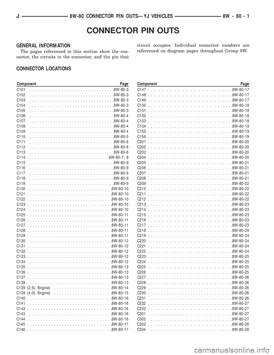
GENERAL INFORMATION
The pages referenced in this section show the con-
nector, the circuits in the connector, and the pin thatcircuit occupies. Individual connector numbers are
referenced on diagram pages throughout Group 8W.
CONNECTOR LOCATIONS
Component Page
C101................................8W-80-3
C102................................8W-80-3
C103................................8W-80-3
C104................................8W-80-3
C105................................8W-80-3
C106................................8W-80-4
C107................................8W-80-4
C108................................8W-80-4
C109................................8W-80-4
C110................................8W-80-5
C111................................8W-80-6
C112................................8W-80-6
C113................................8W-80-6
C114...............................8W-80-7, 8
C115................................8W-80-9
C116................................8W-80-9
C117................................8W-80-9
C118................................8W-80-9
C119................................8W-80-9
C120................................8W-80-10
C121................................8W-80-10
C122................................8W-80-10
C123................................8W-80-10
C124................................8W-80-10
C125................................8W-80-11
C126................................8W-80-11
C127................................8W-80-11
C128................................8W-80-11
C129................................8W-80-11
C130................................8W-80-12
C131................................8W-80-12
C132................................8W-80-12
C133................................8W-80-12
C134................................8W-80-12
C135................................8W-80-13
C136................................8W-80-13
C137................................8W-80-13
C138................................8W-80-13
C139 (2.5L Engine)......................8W-80-14
C139 (4.0L Engine)......................8W-80-15
C140................................8W-80-16
C141................................8W-80-16
C142................................8W-80-16
C143................................8W-80-16
C144................................8W-80-16
C145................................8W-80-17
C146................................8W-80-17Component Page
C147................................8W-80-17
C148................................8W-80-17
C149................................8W-80-17
C150................................8W-80-18
C151................................8W-80-18
C152................................8W-80-18
C153................................8W-80-18
C154................................8W-80-19
C155................................8W-80-19
C156................................8W-80-19
C201................................8W-80-20
C202................................8W-80-20
C203................................8W-80-20
C204................................8W-80-20
C205................................8W-80-21
C206................................8W-80-21
C207................................8W-80-21
C208................................8W-80-21
C209................................8W-80-22
C210................................8W-80-22
C211................................8W-80-22
C212................................8W-80-22
C213................................8W-80-23
C214................................8W-80-23
C215................................8W-80-23
C216................................8W-80-23
C217................................8W-80-23
C218................................8W-80-24
C219................................8W-80-24
C220................................8W-80-24
C221................................8W-80-24
C222................................8W-80-24
C223................................8W-80-25
C224................................8W-80-25
C225................................8W-80-25
C226................................8W-80-25
C227................................8W-80-26
C228................................8W-80-26
C229................................8W-80-26
C230................................8W-80-26
C231................................8W-80-26
C232................................8W-80-27
C233................................8W-80-27
C301................................8W-80-27
C302................................8W-80-27
C303................................8W-80-28
C304................................8W-80-28
J8W-80 CONNECTOR PIN OUTSÐYJ VEHICLES 8W - 80 - 1
Page 1262 of 2158
CONNECTOR LOCATIONS
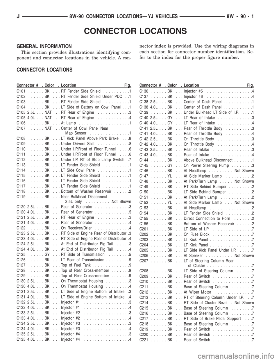
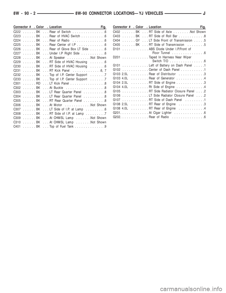
GENERAL INFORMATION
This section provides illustrations identifying com-
ponent and connector locations in the vehicle. A con-nector index is provided. Use the wiring diagrams in
each section for connector number identification. Re-
fer to the index for the proper figure number.
CONNECTOR LOCATIONS
Connector # . Color . Location Fig.
C101......BK ...RTFender Side Shield..........1
C102......BK ...RTFender Side Shield Under PDC . .1
C103......BK ...RTFender Side Shield..........1
C104......BK ...LTSide of Battery on Cowl Panel . . .1
C105 2.5L . . . NAT . . RT Rear of Engine............3
C105 4.0L . . . NAT . . RT Rear of Engine............4
C106......BK ...AtLamp...................1
C107......NAT ..Center of Cowl Panel Near
Map Sensor...............1
C108......BK ...LTKick Panel Above Park Brake . . .8
C109......BK ...Under Drivers Seat............8
C110......BK ...Under I.P.Front of Floor Tunnel....6
C111......BK ...Under I.P.Front of Floor Tunnel....6
C112......BK ...Under I.P. RT of Stop Lamp Switch .7
C113......BK ...LTFender Side Shield..........1
C114......BK ...LTSide Cowl Panel............1
C115......BK ...LTFender Side Shield..........1
C116......BK ...LTFender Side Shield..........1
C117......BK ...LTFender Side Shield..........1
C118......BK ...Bottom of Washer Reservoir......2
C119......BK ...Near Bulkhead Disconnect
2.5L only..........Not Shown
C120 2.5L . . . BK . . . Rear of Generator.............3
C120 4.0L . . . BK . . . Rear of Generator.............5
C121 2.5L . . . BK . . . RT Rear of Engine............3
C121 4.0L . . . BK . . . Rear of Generator.............4
C122......BK ...OnReceiver/Drier.............4
C123 2.5L . . . BK . . . RT Side of Engine Rear of Distributor .3
C123 4.0L . . . BK . . . RT Side of Engine Rear of Distributor .4
C124 2.5L . . . BK . . . At End of Distributor Pig Tail.....3
C124 4.0L . . . BK . . . At End of Distributor Pig Tail.....4
C125......GY ...RTSide of Transmission........5
C126......BK ...LTRear of Transmission.........5
C127......BK ...TopofFuel Tank..............9
C128......BK ...TopofRear Cross-member.......9
C129......BK ...TopofRear Cross-member.......9
C130 2.5L . . . BK . . . On Thermostat Housing.........3
C130 4.0L . . . BK . . . On Thermostat Housing.........4
C131 2.5L . . . BK . . . LT Side of Engine Bottom of Intake .3
C131 4.0L . . . BK . . . LT Side of Engine Bottom of Intake .4
C132 2.5L . . . BK . . . Injector #1.................3
C132 4.0L . . . BK . . . Injector #1.................4
C133 2.5L . . . BK . . . Injector #2.................3
C133 4.0L . . . BK . . . Injector #2.................4
C134 2.5L . . . BK . . . Injector #3.................3
C134 4.0L . . . BK . . . Injector #3.................4
C135 2.5L . . . BK . . . Injector #4.................3
C135 4.0L . . . BK . . . Injector #4.................4Connector # . Color . Location Fig.
C136......BK ...Injector #5.................4
C137......BK ...Injector #6.................4
C138 2.5L . . . BK . . . Center of Dash Panel...........1
C138 4.0L . . . BK . . . Center of Dash Panel...........1
C139......BK ...Under Bulkhead LT Side of I.P.....1
C140 2.5L . . . GY . . . LT Rear of Intake.............3
C140 4.0L . . . GY . . . LT Rear of Intake.............4
C141 2.5L . . . BK . . . Rear of Throttle Body..........3
C141 4.0L . . . BK . . . Rear of Throttle Body..........4
C142 2.5L . . . BK . . . On Throttle Body.............3
C142 4.0L . . . BK . . . On Throttle Body.............4
C143 2.5L . . . BK . . . Rear of Intake...............3
C143 4.0L . . . BK . . . Rear of Intake...............4
C144......BK ...Above Bulkhead Disconnect.......1
C145......GY ...OnPower Steering Pump........3
C146......BK ...AtHeadlamp..........Not Shown
C147......YL ...AtSide Marker Lamp..........2
C148......BK ...AtPark/Turn Lamp......Not Shown
C149......BK ...RTSide Behind Bumper.........2
C150......BK ...LTSide Behind Bumper.........2
C151......BK ...AtPark/Turn Lamp............2
C152......YL ...AtSide Marker Lamp. . . .Not Shown
C153......BK ...AtHeadlamp................2
C154......BK ...LTFender Side Shield..........2
C155......BK ...Direct Connection to Horn.......2
C156......BK ...Bottom of Washer Reservoir......2
C201......BK ...LTSide of I.P...............7
C202......BK ...OnFuse Block...............7
C203......BK ...LTKick Panel................7
C204......BK ...LTKick Panel................7
C205......BK ...LTSide Kick Panel Under I.P......7
C206......BK ...AtSpeaker...........Not Shown
C207......BK ...LTofSteering Column Rear
of Cluster.................7
C208......BK ...LTSide of Steering Column......7
C209......BK ...Rear of Switch...............7
C210......BK ...Rear of Switch...............7
C211......BK ...Base of Steering Column........7
C212......BK ...AtWiper Motor..............7
C213......BK ...RTofSteering Column Under I.P. . .7
C214......BK ...RTSide of Cluster Bezel . .Not Shown
C215......BK ...Base of Steering Column........7
C216......BK ...Base of Steering Column........7
C217......BK ...RTSide of Brake Pedal Support . . .7
C218......BK ...Base of Steering Column........7
C219......BK ...Rear of Switch...............7
C220......BK ...Rear of Switch...............7
C221......BK ...Rear of Switch...............7
J8W-90 CONNECTOR LOCATIONSÐYJ VEHICLES 8W - 90 - 1
Page 1263 of 2158
Connector # . Color . Location Fig.
C222......BK ...Rear of Switch...............6
C223......BK ...Rear of HVAC Switch...........6
C224......BK ...Rear of Radio...............6
C225......BK ...Rear Center of I.P.............6
C226......BK ...Rear of Glove Box LT Side.......6
C227......BK ...Under I.P Right Side...........6
C228......BK ...AtSpeaker...........Not Shown
C229......BK ...RTSide of HVAC Housing.......6
C230......BK ...RTSide of HVAC Housing.......6
C231......BK ...RTKick Panel.............6,7
C232......BK ...TopofI.P.Center Support.......7
C233......BK ...TopofI.P.Center Support.......7
C301......RD ...LTKick Panel................8
C302......BK ...AtBuckle..................8
C303......BK ...LTRear Quarter Panel..........8
C304......BK ...LTRear Quarter Panel..........8
C305......BK ...RTRear Quarter Panel..........8
C306......BK ...AtMotor............Not Shown
C307......BK ...LTSide of I.P. at Lamp.........6
C308......BK ...RTSide of I.P. at Lamp.........7
C309......BK ...AtCHMSL Lamp.......Not Shown
C310......BK ...AtCHMSL Lamp.......Not Shown
C401......BK ...TopofFuel Tank..............9Connector # . Color . Location Fig.
C402......BK ...RTSide of Axle........Not Shown
C403......BK ...RTSide of Roll Bar............8
C404......GY ...LTSide Front of Transmission.....5
C405......BK ...RTSide of Transmission........5
D101............ABSDiode Under I.P.Front of
Floor Tunnel...............6
D201............Taped In Harness Near Wiper
Switch T/O................6
G101............Left of Battery on Dash Panel.....1
G102............Center of Dash Panel...........1
G103 2.5L . .......Rear of Distributor............3
G103 4.0L . .......Rear of Generator.............4
G104 2.5L . .......RTSide of Engine.............3
G104 4.0L . .......RtSide of Engine.............4
G105............RTSide Radiator Closure Panel....2
G106............LTSide Radiator Closure Panel....2
G107............RTSide of Dash Panel.........1
G108 2.5L . .......RTRear of Engine............3
G108 4.0L . .......RTRear of Engine............4
G201.............AtCigar Lighter..............6
G202.............Rear of Radio...............6
8W - 90 - 2 8W-90 CONNECTOR LOCATIONSÐYJ VEHICLESJ
Page 1264 of 2158
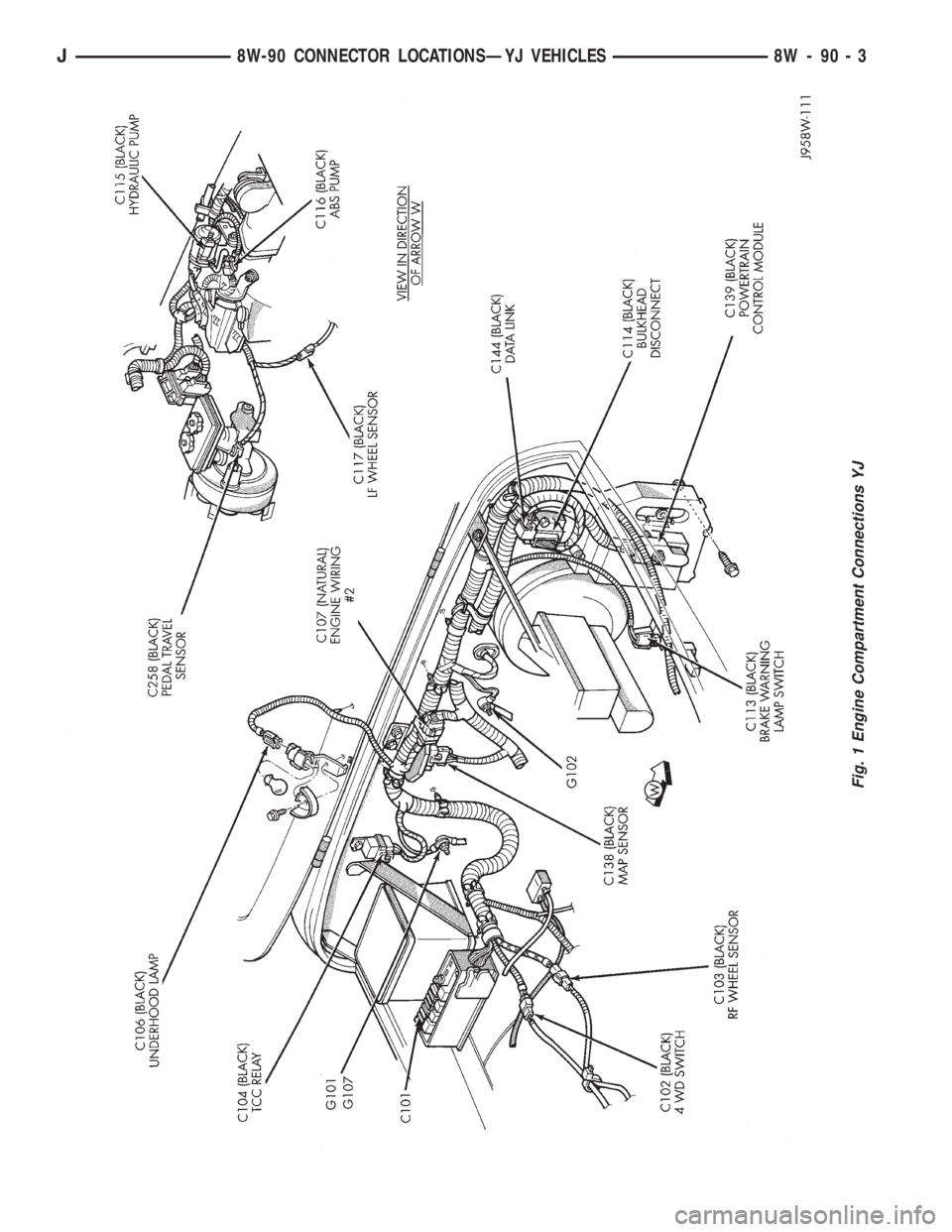
Fig. 1 Engine Compartment Connections YJ
J8W-90 CONNECTOR LOCATIONSÐYJ VEHICLES 8W - 90 - 3
Page 1265 of 2158
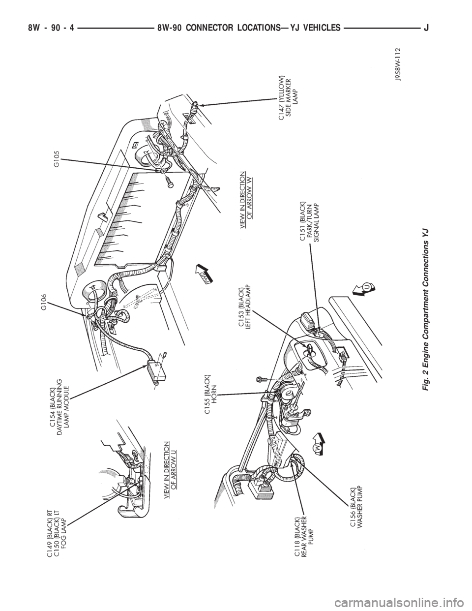
Fig. 2 Engine Compartment Connections YJ
8W - 90 - 4 8W-90 CONNECTOR LOCATIONSÐYJ VEHICLESJ
Page 1266 of 2158
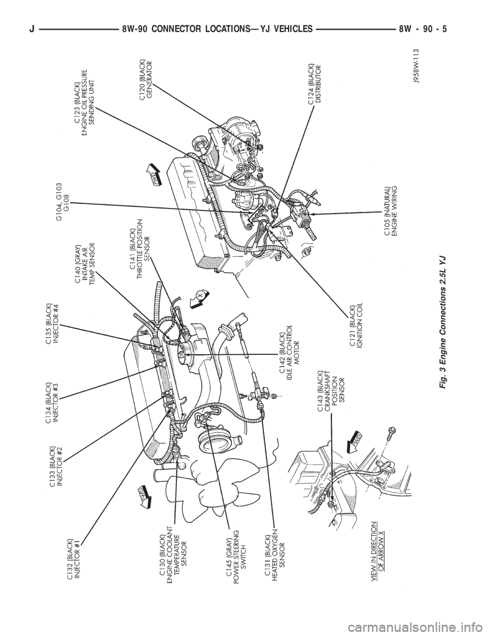
Fig. 3 Engine Connections 2.5L YJ
J8W-90 CONNECTOR LOCATIONSÐYJ VEHICLES 8W - 90 - 5
Page 1267 of 2158
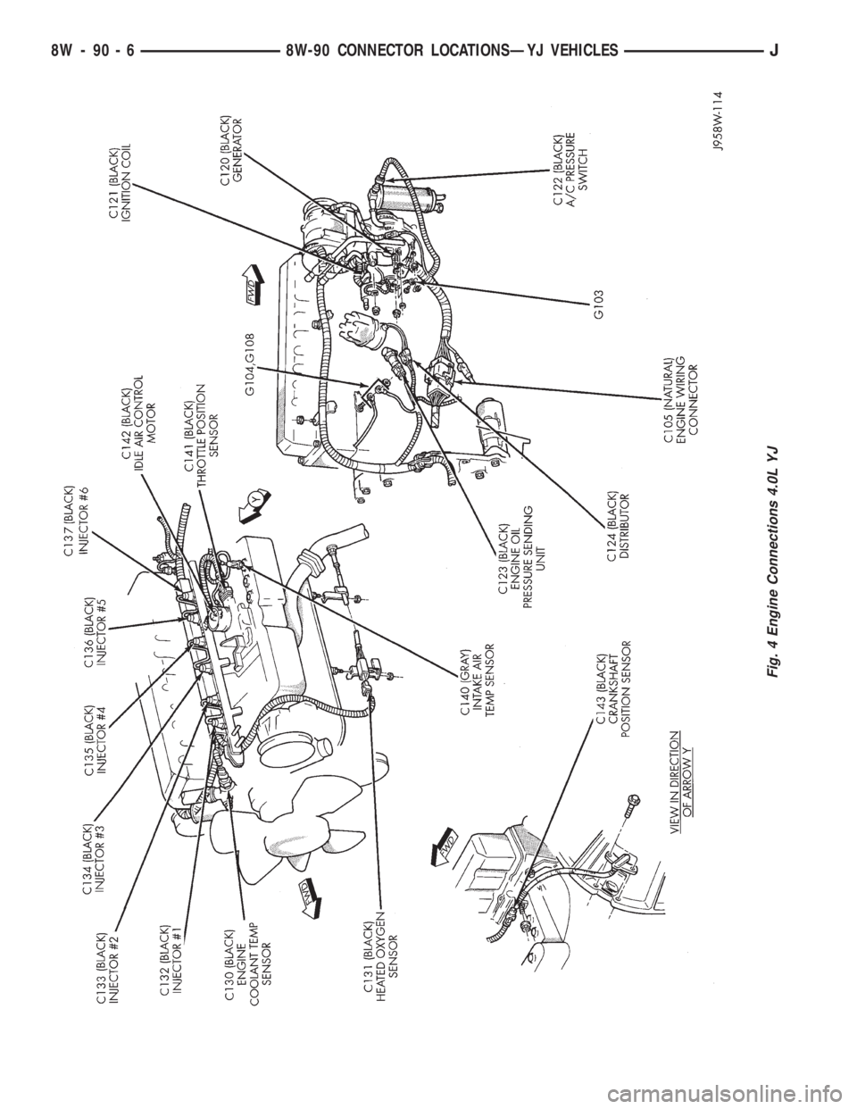
Fig. 4 Engine Connections 4.0L YJ
8W - 90 - 6 8W-90 CONNECTOR LOCATIONSÐYJ VEHICLESJ
Page 1273 of 2158
SPLICE LOCATIONS
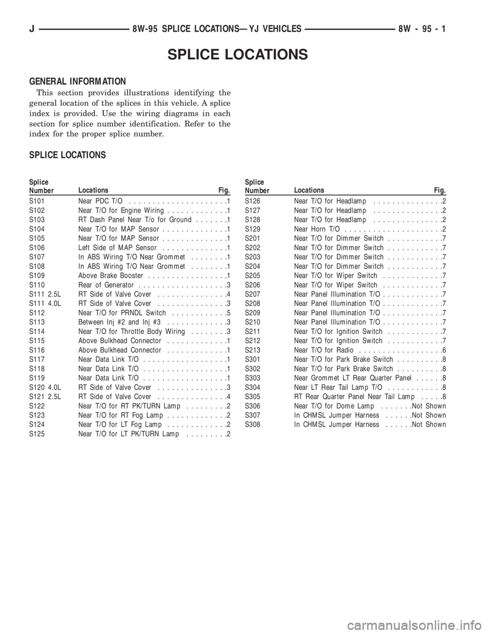
GENERAL INFORMATION
This section provides illustrations identifying the
general location of the splices in this vehicle. A splice
index is provided. Use the wiring diagrams in each
section for splice number identification. Refer to the
index for the proper splice number.
SPLICE LOCATIONS
Splice
NumberLocations Fig.
S101 Near PDC T/O.....................1
S102 Near T/O for Engine Wiring.............1
S103 RT Dash Panel Near T/o for Ground.......1
S104 Near T/O for MAP Sensor..............1
S105 Near T/O for MAP Sensor..............1
S106 Left Side of MAP Sensor..............1
S107 In ABS Wiring T/O Near Grommet........1
S108 In ABS Wiring T/O Near Grommet........1
S109 Above Brake Booster.................1
S110 Rear of Generator...................3
S111 2.5L RT Side of Valve Cover...............4
S111 4.0L RT Side of Valve Cover...............3
S112 Near T/O for PRNDL Switch............5
S113 Between Inj #2 and Inj #3.............3
S114 Near T/O for Throttle Body Wiring........3
S115 Above Bulkhead Connector.............1
S116 Above Bulkhead Connector.............1
S117 Near Data Link T/O..................1
S118 Near Data Link T/O..................1
S119 Near Data Link T/O..................1
S120 4.0L RT Side of Valve Cover...............3
S121 2.5L RT Side of Valve Cover...............4
S122 Near T/O for RT PK/TURN Lamp.........2
S123 Near T/O for RT Fog Lamp.............2
S124 Near T/O for LT Fog Lamp.............2
S125 Near T/O for LT PK/TURN Lamp.........2Splice
NumberLocations Fig.
S126 Near T/O for Headlamp...............2
S127 Near T/O for Headlamp...............2
S128 Near T/O for Headlamp...............2
S129 Near Horn T/O.....................2
S201 Near T/O for Dimmer Switch............7
S202 Near T/O for Dimmer Switch............7
S203 Near T/O for Dimmer Switch............7
S204 Near T/O for Dimmer Switch............7
S205 Near T/O for Wiper Switch.............7
S206 Near T/O for Wiper Switch.............7
S207 Near Panel Illumination T/O.............7
S208 Near Panel Illumination T/O.............7
S209 Near Panel Illumination T/O.............7
S210 Near Panel Illumination T/O.............7
S211 Near T/O for Ignition Switch............7
S212 Near T/O for Ignition Switch............7
S213 Near T/O for Radio..................6
S301 Near T/O for Park Brake Switch..........8
S302 Near T/O for Park Brake Switch..........8
S303 Near Grommet LT Rear Quarter Panel......8
S304 Near LT Rear Tail Lamp T/O............8
S305 RT Rear Quarter Panel Near Tail Lamp.....8
S306 Near T/O for Dome Lamp.......Not Shown
S307 In CHMSL Jumper Harness......Not Shown
S308 In CHMSL Jumper Harness......Not Shown
J8W-95 SPLICE LOCATIONSÐYJ VEHICLES 8W - 95 - 1