1995 JEEP XJ engine
[x] Cancel search: enginePage 865 of 2158

HELPFUL INFORMATION
²If the system loses ground for the Z11 circuits at
the right rear of the engine, the vehicle will not op-
erate. Check the connection at the ganged-ground cir-
cuit eyelet.
²Circuit F12 splices to supply battery voltage to the
vehicle speed control switch, back-up lamp switch,
A/C compressor clutch relay, windshield washer fluid
level sensor and radiator fan relay.
BRAKE SWITCH INPUT
Circuit K29 provides the brake switch input to the
PCM. Circuit K29 connects to cavity 29 of the PCM.
POWER (DEVICE) GROUND
Circuit Z12 connects to cavities 11 and 12 of the
PCM. The Z12 circuit provides ground for PCM inter-
nal drivers that operate high current devices like the
injectors and ignition coil.
Internal to the PCM, the power (device) ground cir-
cuit connects to the PCM sensor return circuit (from
circuit K4).
HELPFUL INFORMATION
²The grounding point for circuit Z12 is the right
rear of the engine.
²If the system loses ground for the Z12 circuits at
the rear of the engine, the vehicle will not operate.
Check the connection at the ganged-ground circuit
eyelet.
DIAGRAM INDEX
Component Page
Automatic Shut Down Relay.................8W-30-6
Camshaft Position Sensor...................8W-30-8
Crankshaft Position Sensor..................8W-30-9
Data Link Connector......................8W-30-11
Distributor Ignition Coil....................8W-30-11
Engine Coolant Temperature Sensor.............8W-30-9
Fuel Injector #1.........................8W-30-7
Fuel Injector #2.........................8W-30-7
Fuel Injector #3.........................8W-30-7
Fuel Injector #4.........................8W-30-7
Fuel Injector #5.........................8W-30-7
Fuel Injector #6.........................8W-30-7
Fuel Pump Relay........................8W-30-12
Fuel Tank Gauge Level Sending Unit...........8W-30-12
Fuse 2 (PDC)...........................8W-30-6
Fuse 6 (PDC)...........................8W-30-6
Fuse 11 (PDC).......................8W-30-6, 11
Fuse 14 (PDC)..........................8W-30-6
Heated Oxygen Sensor....................8W-30-10
Idle Air Control Motor.....................8W-30-10
Ignition Switch.......................8W-30-6, 12
Instrument Cluster....................8W-30-11, 12
Intake Air Temperature Sensor................8W-30-9
MAP Sensor............................8W-30-8
Powertrain Control Module.............8W-30-6 thru 12
Throttle Position Sensor....................8W-30-8
Vehicle Speed Sensor.....................8W-30-11
J8W-30 FUEL/IGNITIONÐXJ-RHD 8W - 30 - 5
Page 873 of 2158

TRANSMISSION CONTROLS
FOUR-WHEEL DRIVE (4WD) SWITCH
When the 4WD switch closes, circuit Z1 provides
ground for the 4WD indicator lamp in the instrument
cluster. Circuit F87 connects to the instrument clus-
ter and supplies battery voltage to the 4WD indicator
lamp. Circuit 107 connects the indicator lamp to the
4WD switch. Circuit 106 connects the lamp to the in-
strument cluster and circuit F87.
TRANSMISSION COMFORT SWITCH
Circuit T17 from fuse 12 in the Power Distribution
Center (PDC) supplies battery voltage to the trans-
mission comfort switch. Circuit Z1 provides ground
for the switch. Circuit T177 Connects the switch to
the Transmission Control Module (TCM).
TRANSMISSION CONTROL MODULE
Vehicles equipped with the 4.0L engine have elec-
tronically controlled solenoids in the automatic trans-
mission valve body.
The transmission control module (TCM) receives
inputs from the throttle position sensor (TPS) on cir-
cuit K22 and the stop lamp switch on circuit K29.
Circuit K4 connects to the TCM to provide ground for
the TPS signal.
The TCM receives the transmission output speed
sensor signal on circuit 505. Circuit A14 from fuse 2
in the Power Distribution Center (PDC) supplies bat-
tery voltage to the TCM. Circuit T17 from fuse 12 in
the PDC also connects to the TCM. Circuit Z12 pro-
vides ground for the TCM.The TCM powers the S1 solenoid on circuit 510,
the S2 solenoid on circuit 509, and the S3 solenoid on
circuit 508. Circuit Z12 provides ground for the S1,
S2, and S3 solenoids.
Circuits 506 and 507 from the Park/Neutral posi-
tion switch connect to the TCM. Circuits 506 and 507
tell the TCM what drive range the transmission is in.
DATA LINK CONNECTOR
Circuit 137 from the TCM connects to the data link
connector. Circuit F39 from fuse 5 in the PDC sup-
plies power to the data link connector. Circuit Z12
provides ground for the data link connector.
DIAGRAM INDEX
Component Page
ABS Data Link Connector...................8W-31-3
4-WD Indicator Lamp......................8W-31-4
4-WD Indicator Switch.....................8W-31-4
Fuse 2 (PDC)...........................8W-31-4
Fuse 6 (PDC).........................8W-31-2, 3
Fuse 11 (PDC)..........................8W-31-3
Fuse 12 (PDC)..........................8W-31-2
Ignition Switch........................8W-31-2, 3
Park/Neutral Position Switch.................8W-31-3
Telltale Connector (Instrument Cluster)...........8W-31-4
Transmission Comfort Switch.................8W-31-2
Transmission Control Module.............8W-31-2, 3, 4
Transmission Valve Body Solenoids.............8W-31-4
J8W-31 TRANSMISSION CONTROLSÐXJ-RHD 8W - 31 - 1
Page 878 of 2158

ABS pump motor relay. The ABS control module pro-
vides ground for the relay on circuit B116. Circuit
B116 connects to cavity 15 of the ABS control mod-
ule.
When the ABS pump motor energizes, it connects
circuit A10 from PDC fuse 8 to circuit B233. Circuit
B233 supplies battery voltage to the pump motor.
Circuit Z12 provides ground for the pump motor.
PUMP MOTOR SPEED SENSOR
The input from the pump motor speed sensor tells
the ABS control module that the pump is operating.
Circuits B219 and B220 from the control module con-
nect to the speed sensor.
BRAKE SWITCH INPUT
Circuit L50 from the stop lamp provides the brake
switch input to the ABS control module. When the
brake pedal is depressed, the stop lamp switch closes
to supply battery voltage from circuit L9 to circuit
L50. Circuit L50 connects to cavity 32 of the ABS
control module. Circuit L9 originates at fuse 4 in the
Power Distribution Center (PDC).
HYDRAULIC CONTROL UNIT
When the ABS power relay energizes, two branches
of circuit B235 splice to supply voltage to the isola-
tion and decay solenoids in the hydraulic control
unit. The hydraulic control unit contains three sepa-
rate isolation solenoids and three separate dump so-
lenoids. The ABS control module activates the decay
and isolation solenoids by providing separate ground
paths for each.
The ABS module provides a ground path for the
rear isolation solenoid on circuit B251. Circuit B251
connects to cavity 54 of the ABS control module.
For the right front isolation solenoid, the ABS mod-
ule provides a ground path on circuit B249. Circuit
B249 connects to cavity 38 of the ABS control mod-
ule.
On circuit B245, the ABS control module provides
ground for the left front isolation solenoid. Circuit
B245 connects to cavity 20 of the ABS control mod-
ule.
The ABS control module provides a ground path for
the rear dump solenoid on circuit B254. Circuit B254
connects to cavity 36 of the ABS control module.For the right front dump solenoid, the ABS module
provides a ground path on circuit B248. Circuit B248
connects to cavity 21 of the ABS control module.
On circuit B243, the ABS module provides ground
for the left dump solenoid. Circuit B243 connects to
cavity 2 of the ABS control module.
ABS WARNING LAMP
Circuit F87 provides power for the ABS warning
lamp at the instrument cluster. Ground for the ABS
warning lamp is provided by either the ABS control
module or by the ABS power relay when the relay is
not energized. The ABS control module illuminates
the lamp by providing ground on circuit B205.
Circuit B205 splices to connect to circuit B235
through a diode. When the ABS power relay is not
energized, it connects circuit B235 to circuit Z12. The
ground path for the warning lamp is through the di-
ode to circuit B235, through the ABS power relay to
ground on circuit Z12.
The diode between circuit B205 and B235 prevents
voltage from flowing to the ABS control module when
the ABS power relay switches to supply power on cir-
cuit B235.
DATA LINK CONNECTOR
Circuit D1 from cavity 23 of the ABS control mod-
ule receives data from the DRB scan tool through the
data link connector. The ABS control module trans-
mits data to the scan tool through the connector on
circuit D2. Circuit D2 originates at cavity 42 of the
ABS control module.
Through the data link connector, circuit Z12 pro-
vides ground for the DRB scan tool. Circuit Z12 ter-
minates at the right rear of the engine.
Circuit A4 from fuse 7 in the Power Distribution
Center (PDC) supplies power to fuse 13 in the PDC.
Fuse 13 powers circuit F39 which supplies battery
voltage to the scan tool through the diagnostic con-
nector.
HELPFUL INFORMATION
²Check fuses 7 and 13 in the PDC.
²If the vehicle is equipped with an automatic trans-
mission, circuits D1 and D2 are double crimped at
the data link connector and connect to the Power-
train Control Module (PCM).
8W - 32 - 2 8W-32 ANTI-LOCK BRAKESÐXJ-RHDJ
Page 891 of 2158
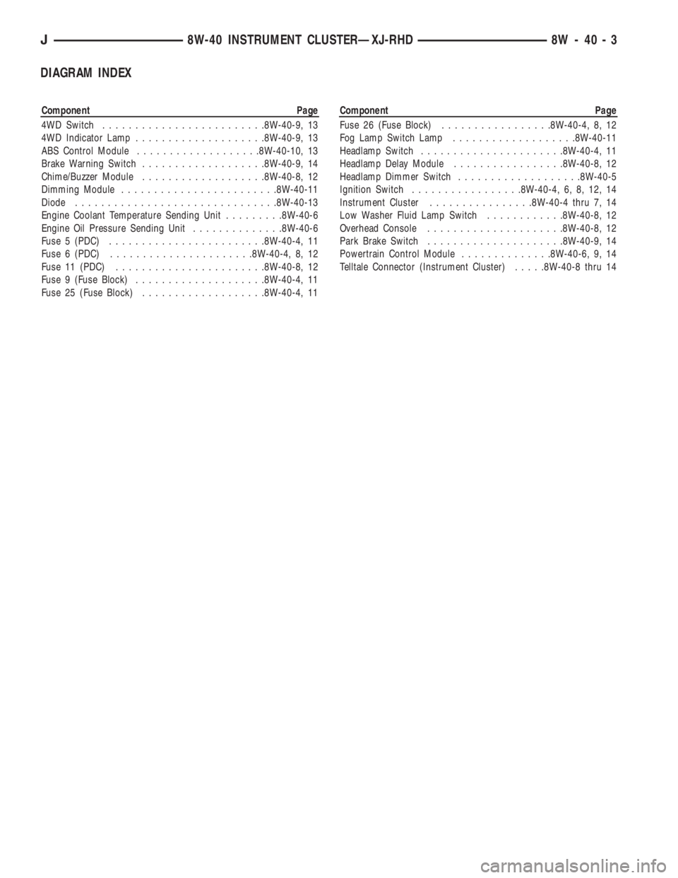
DIAGRAM INDEX
Component Page
4WD Switch.........................8W-40-9, 13
4WD Indicator Lamp....................8W-40-9, 13
ABS Control Module...................8W-40-10, 13
Brake Warning Switch...................8W-40-9, 14
Chime/Buzzer Module...................8W-40-8, 12
Dimming Module........................8W-40-11
Diode...............................8W-40-13
Engine Coolant Temperature Sending Unit.........8W-40-6
Engine Oil Pressure Sending Unit..............8W-40-6
Fuse 5 (PDC)........................8W-40-4, 11
Fuse 6 (PDC)......................8W-40-4, 8, 12
Fuse 11 (PDC).......................8W-40-8, 12
Fuse 9 (Fuse Block)....................8W-40-4, 11
Fuse 25 (Fuse Block)...................8W-40-4, 11Component Page
Fuse 26 (Fuse Block).................8W-40-4, 8, 12
Fog Lamp Switch Lamp...................8W-40-11
Headlamp Switch......................8W-40-4, 11
Headlamp Delay Module.................8W-40-8, 12
Headlamp Dimmer Switch...................8W-40-5
Ignition Switch.................8W-40-4, 6, 8, 12, 14
Instrument Cluster................8W-40-4 thru 7, 14
Low Washer Fluid Lamp Switch............8W-40-8, 12
Overhead Console.....................8W-40-8, 12
Park Brake Switch.....................8W-40-9, 14
Powertrain Control Module..............8W-40-6, 9, 14
Telltale Connector (Instrument Cluster).....8W-40-8 thru 14
J8W-40 INSTRUMENT CLUSTERÐXJ-RHD 8W - 40 - 3
Page 908 of 2158
fuse 4 in the fuse block. Fuse 4 supplies power to the
A/C-Heater control switch on circuit C7.
Circuit C43 from the A/C-heater switch splices to
supply voltage to the blower motor switch and the
blower motor resistor block. The blower motor switch
sets blower motor speed to HIGH, M1, M2, or LOW.
When the blower motor switch is in the LOW posi-
tion, circuit C43 from the A/C-Heater switch supplies
voltage to the resistor block. Voltage does not pass
through the blower motor switch in the LOW position
In the M1 position, the blower motor switch sup-
plies voltage to the resistor block on circuit C4. From
circuit C4, voltage passes through three resistors in
the resistor block to the blower motor on circuit C1.
In the M2 position, the blower motor supplies volt-
age to the resistor block on circuit C6. From circuit
C6 voltage flows through two resistors to the blower
motor on circuit C1.
In the HIGH position, the blower motor switch con-
nects directly to the blower motor on circuit C1. Volt-
age does not pass through the resistor block in the
HIGH position.
Circuit Z1 provides ground for the blower motor.
AIR CONDITIONING OPERATION
When the A/C-heater control switch is moved to an
A/C position or the defrost position, the Powertrain
Control Module (PCM) receives the A/C select signal
on circuit C90. Circuit C90 connects to cavity 28 of
the PCM.
Circuit also C90 splices to the low pressure switch
and to supply battery voltage to the coil side of the
A/C compressor clutch relay. If the low pressure
switch is closed, circuit C90 connects to circuit C21.
Circuit C21 supplies battery voltage to the A/C cy-
cling switch. Circuit C91 from the A/C cycling switch
provides the A/C request signal to the PCM. Circuit
C91 connects to cavity 27 of the PCM. Circuit Z1 pro-
vides ground for the A/C cycling switch.
After receiving the A/C request signal, the PCM
supplies ground for the A/C compressor clutch relay
on circuit C13. Circuit F12 from fuse 11 in the PDC
supplies battery voltage to the contact side of the A/C
compressor clutch relay. When the PCM grounds the
relay, the contacts close and connect circuit F12 to
circuit C3. Circuit C3 feeds the A/C compressor
clutch.
Also after receiving the A/C request signal, the
PCM supplies ground for the coil side of the radiator
fan relay on circuit C27 (4.0L engine). Circuit C27
connects to cavity 31 of the PCM. Circuit F12 sup-
plies battery voltage to the coil side of the relay.When the PCM grounds the coil side of the radia-
tor fan relay, the contacts close and connect circuit
F141 from fuse 15 in the PDC to circuit C25. Circuit
C25 feeds the radiator fan motor. Circuit Z1 provides
ground for the motor.
HELPFUL INFORMATION
Circuit A14 from PDC fuse 2 powers circuit F141
through fuse 15 in the PDC.
RADIATOR FAN RELAY AND MOTOR
In the START or RUN positions, the ignition
switch connects circuit A1 from fuse 6 in the Power
Distribution Center (PDC) to circuit A21. Circuit A21
powers a bus bar in the PDC that feeds circuit F12
through fuse 11. Circuit F12 feeds the coil side of the
radiator fan relay.
The PCM supplies ground for the coil side of the
radiator fan relay on circuit C27. Circuit C27 con-
nects to cavity 31 of the PCM.
When the PCM grounds the coil side of the radia-
tor fan relay, the contacts close and connect circuit
F141 from fuse 15 in the PDC to circuit C25. Circuit
C25 feeds the radiator fan motor. Circuit Z1 provides
ground for the radiator fan motor.
HELPFUL INFORMATION
Circuit A14 from PDC fuse 2 powers circuit F141
through fuse 15 in the PDC.
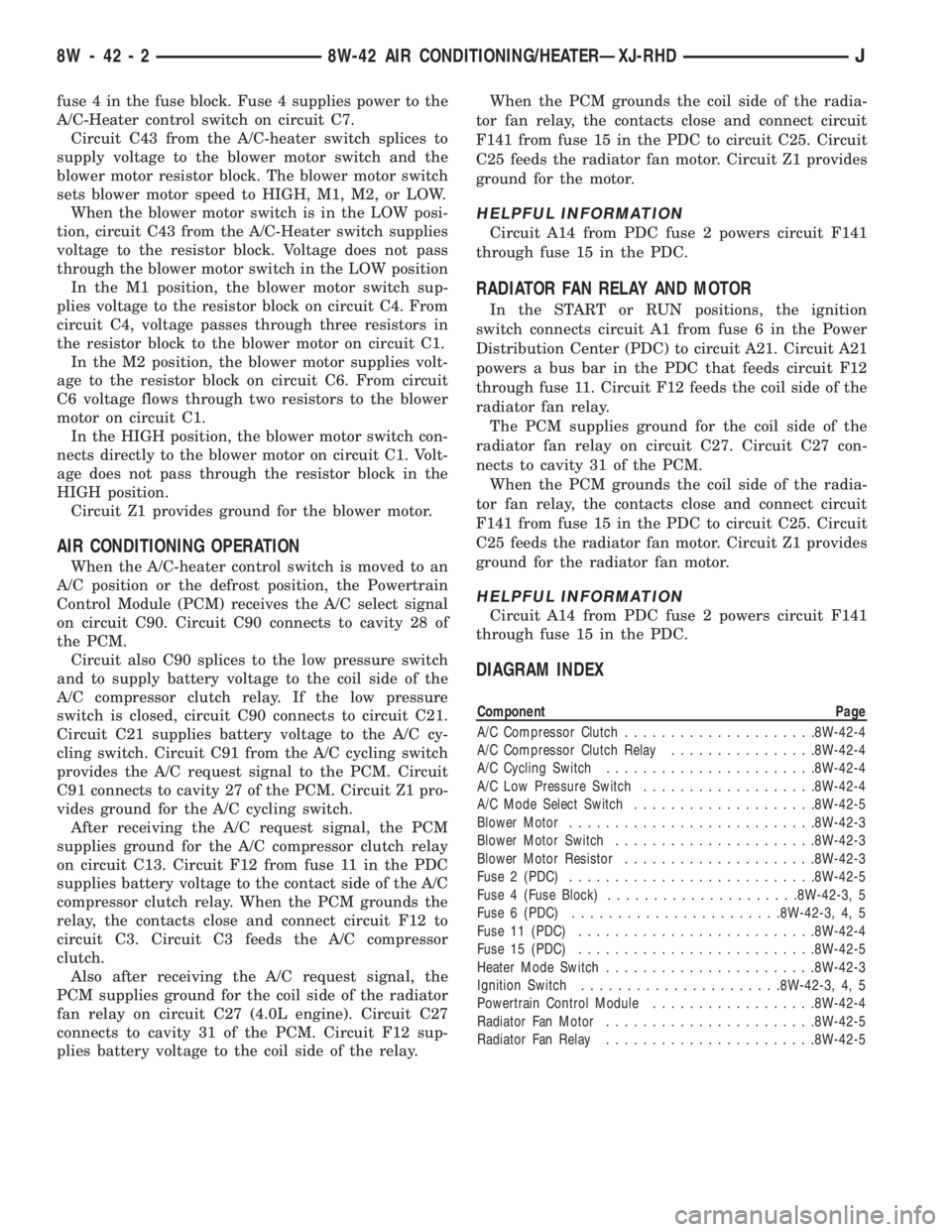
DIAGRAM INDEX
Component Page
A/C Compressor Clutch.....................8W-42-4
A/C Compressor Clutch Relay................8W-42-4
A/C Cycling Switch.......................8W-42-4
A/C Low Pressure Switch...................8W-42-4
A/C Mode Select Switch....................8W-42-5
Blower Motor...........................8W-42-3
Blower Motor Switch......................8W-42-3
Blower Motor Resistor.....................8W-42-3
Fuse 2 (PDC)...........................8W-42-5
Fuse 4 (Fuse Block).....................8W-42-3, 5
Fuse 6 (PDC).......................8W-42-3, 4, 5
Fuse 11 (PDC)..........................8W-42-4
Fuse 15 (PDC)..........................8W-42-5
Heater Mode Switch.......................8W-42-3
Ignition Switch......................8W-42-3, 4, 5
Powertrain Control Module..................8W-42-4
Radiator Fan Motor.......................8W-42-5
Radiator Fan Relay.......................8W-42-5
8W - 42 - 2 8W-42 AIR CONDITIONING/HEATERÐXJ-RHDJ
Page 1067 of 2158
CONNECTOR LOCATIONS
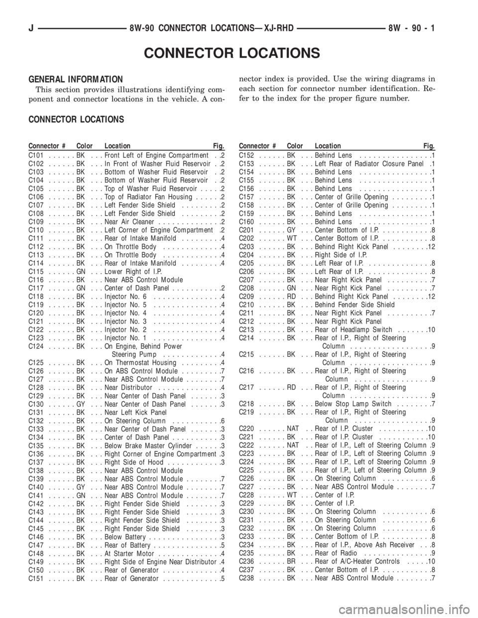
GENERAL INFORMATION
This section provides illustrations identifying com-
ponent and connector locations in the vehicle. A con-nector index is provided. Use the wiring diagrams in
each section for connector number identification. Re-
fer to the index for the proper figure number.
CONNECTOR LOCATIONS
Connector # Color Location Fig.
C101......BK ...Front Left of Engine Compartment . .2
C102......BK ...InFront of Washer Fluid Reservoir . .2
C103......BK ...Bottom of Washer Fluid Reservoir . .2
C104......BK ...Bottom of Washer Fluid Reservoir . .2
C105......BK ...TopofWasher Fluid Reservoir.....2
C106......BK ...TopofRadiator Fan Housing......2
C107......BK ...Left Fender Side Shield.........2
C108......BK ...Left Fender Side Shield.........2
C109......BK ...Near Air Cleaner..............2
C110......BK ...Left Corner of Engine Compartment .2
C111......BK ...Rear of Intake Manifold.........4
C112......BK ...OnThrottle Body.............4
C113......BK ...OnThrottle Body.............4
C114......BK ...Rear of Intake Manifold.........4
C115......GN ...Lower Right of I.P.
C116......BK ...Near ABS Control Module
C117......GN ...Center of Dash Panel...........2
C118......BK ...Injector No. 6...............4
C119......BK ...Injector No. 5...............4
C120......BK ...Injector No. 4...............4
C121......BK ...Injector No. 3...............4
C122......BK ...Injector No. 2...............4
C123......BK ...Injector No. 1...............4
C124......BK ...OnEngine, Behind Power
Steering Pump.............4
C125......BK ...OnThermostat Housing.........4
C126......BK ...OnABSControl Module.........7
C127......BK ...Near ABS Control Module........7
C128......BK ...Near Distributor..............4
C129......BK ...Near Center of Dash Panel.......3
C130......GY ...Near Center of Dash Panel.......3
C131......BK ...Near Left Kick Panel
C132......BK ...OnSteering Column...........6
C133......BK ...Near Center of Dash Panel.......3
C134......BK ...Center of Dash Panel...........3
C135......BK ...Below Brake Master Cylinder......3
C136......BK ...Right Corner of Engine Compartment .3
C137......BK ...Right Side of Hood............3
C138......BK ...Near ABS Control Module
C139......BK ...Near ABS Control Module........7
C140......GY ...Near ABS Control Module........7
C141......GN ...Near ABS Control Module........7
C142......BK ...Right Fender Side Shield........3
C143......BK ...Right Fender Side Shield........3
C144......BK ...Right Fender Side Shield........3
C145......BK ...Right Fender Side Shield........3
C146......BK ...Below Battery................3
C147......BK ...Rear of Battery...............5
C148......BK ...AtStarter Motor..............4
C149......BK ...Right Side of Engine Near Distributor .4
C150......BK ...Rear of Generator.............4
C151......BK ...Rear of Generator.............5Connector # Color Location Fig.
C152......BK ...Behind Lens................1
C153......BK ...Left Rear of Radiator Closure Panel .1
C154......BK ...Behind Lens................1
C155......BK ...Behind Lens................1
C156......BK ...Behind Lens................1
C157......BK ...Center of Grille Opening.........1
C158......BK ...Center of Grille Opening.........1
C159......BK ...Behind Lens................1
C160......BK ...Behind Lens................1
C201......GY ...Center Bottom of I.P............8
C202......WT ...Center Bottom of I.P............8
C203......BK ...Behind Right Kick Panel........12
C204......BK ...Right Side of I.P.
C205......BK ...Left Rear of I.P...............8
C206......BK ...Left Rear of I.P...............8
C207......BK ...Near Right Kick Panel..........7
C208......GN ...Near Right Kick Panel..........7
C209......RD ...Behind Right Kick Panel........12
C210......BK ...Behind Fender Side Shield
C211......BK ...Near Right Kick Panel..........7
C212......BK ...Near Right Kick Panel
C213......BK ...Rear of Headlamp Switch.......10
C214......BK ...Rear of I.P., Right of Steering
Column..................9
C215......BK ...Rear of I.P., Right of Steering
Column..................9
C216......BK ...Rear of I.P., Right of Steering
Column.................9
C217......RD ...Rear of I.P., Right of Steering
Column..................9
C218......BK ...Below Stop Lamp Switch........7
C219......BK ...Rear of I.P., Right of Steering
Column.................9
C220......NAT ..Rear of I.P. Cluster...........10
C221......BK ...Rear of I.P. Cluster...........10
C222......NAT ..Rear of I.P., Left of Steering Column .9
C223......BK ...Rear of I.P., Left of Steering Column .9
C224......BK ...Rear of I.P., Left of Steering Column .9
C225......BK ...Rear of I.P., Left of Steering Column .9
C226......BK ...OnSteering Column...........6
C227......BK ...Near ABS Control Module........7
C228......WT ...Center of I.P.
C229......BK ...Center of I.P.
C230......BK ...OnSteering Column...........6
C231......BK ...OnSteering Column...........6
C232......BK ...OnSteering Column...........6
C233......BK ...Center Bottom of I.P............8
C234......BK ...Rear of I.P., Above Ash Receiver . . .8
C235......BK ...Rear of Radio...............9
C236......BR ...Rear of A/C-Heater Controls.....10
C237......BK ...Center Bottom of I.P............8
C238......BK ...Near ABS Control Module........7
J8W-90 CONNECTOR LOCATIONSÐXJ-RHD 8W - 90 - 1
Page 1068 of 2158
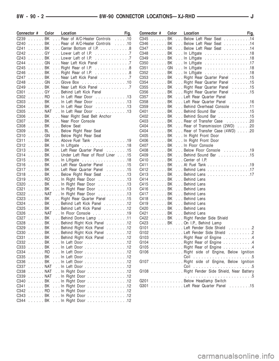
Connector # Color Location Fig.
C239......BK ...Rear of A/C-Heater Controls.....10
C240......BK ...Rear of A/C-Heater Controls.....10
C241......BK ...Center Bottom of I.P............8
C242......GY ...Lower Left of I.P..............7
C243......BK ...Lower Left of I.P..............7
C244......GN ...Near Left Kick Panel...........7
C245......BK ...Right Rear of I.P..............8
C246......BK ...Right Rear of I.P..............8
C247......BK ...Near Left Kick Panel...........7
C248......GN ...Glove Box.................10
C249......BK ...Near Left Kick Panel...........7
C301......GY ...Behind Left Kick Panel
C302......RD ...InLeft Rear Door............13
C303......BK ...InLeft Rear Door............13
C304......BK ...InLeft Rear Door............13
C305......NAT ..InLeft Rear Door............13
C306......BK ...Near Right Seat Belt Anchor
C307......BK ...Near Floor Console
C308......BK ...Below Seat
C309......BL ...Below Right Rear Seat
C310......GN ...Below Right Rear Seat
C311......BK ...Above Fuel Tank.............19
C312......BK ...InLiftgate.................18
C313......BK ...Left Rear Quarter Panel........15
C314......BK ...Under Left Rear of Roof Liner....15
C315......BK ...InLiftgate.................18
C316......BK ...Left Rear Quarter Panel........15
C317......BK ...Left Rear Quarter Panel........15
C318......BK ...Below Right Rear Seat.........13
C319......RD ...InRight Rear Door...........13
C320......BK ...InRight Rear Door...........13
C321......BK ...InRight Rear Door...........13
C322......NAT ..InRight Rear Door...........13
C323......BK ...Right Rear Quarter Panel.......15
C324......BK ...Behind Left Kick Panel.........12
C325......BK ...Behind Left Kick Panel.........12
C326......NAT ..InFloor Console.............19
C327......BK ...Behind Dome Lamp...........11
C328......BK ...Behind Right Kick Panel........12
C329......BK ...Behind Right Kick Panel........12
C330......BK ...Behind Right Kick Panel........12
C331......BK ...Behind Right Kick Panel........12
C332......BK ...InLeft Door................12
C333......BK ...InLeft Door................12
C334......RD ...InLeft Door................12
C335......BK ...InLeft Door................12
C336......BK ...InLeft Door................12
C337......NAT ..InLeft Door................12
C338......NAT ..InRight Door...............12
C339......NAT ..InRight Door...............12
C340......BK ...InRight Door...............12
C341......BK ...InRight Door...............12
C342......RD ...InRight Door...............12
C343......BK ...InRight Door...............12
C344......BK ...InRight Door...............12Connector # Color Location Fig.
C345......BK ...Below Left Rear Seat..........14
C346......BK ...Below Left Rear Seat..........14
C347......BK ...Below Left Rear Seat..........14
C348......BK ...InLiftgate.................18
C349......BK ...InLiftgate.................18
C350......BK ...InLiftgate.................17
C351......GN ...InLiftgate.................18
C352......BK ...InLiftgate.................18
C353......BK ...Right Rear Quarter Panel.......15
C354......BK ...Right Rear Quarter Panel.......15
C355......BK ...Right Rear Quarter Panel.......15
C356......BK ...Right Rear Quarter Panel.......15
C357......BK ...Left Rear Quarter Panel
C358......BK ...Left Rear Quarter Panel........16
C359......BK ...Behind Overhead Console.......11
C401......BK ...Behind Sound Bar............15
C402......BK ...Behind Sound Bar............15
C403......BK ...Rear of Transfer Case.........20
C404......BK ...Rear of Transmission (2WD).....20
C404......BK ...Rear of Transfer Case (4WD).....20
C405......BK ...InRight Front Door
C406......BK ...InRight Front Door
C407......BK ...InFloor Console
C408......BK ...Below Floor Console..........19
C409......BK ...Behind Sound Bar............15
C410......BK ...Center of I.P.
C411......BK ...AtFuel Tank................19
C412......BK ...Behind Lens................17
C413......BK ...Behind Lens................17
C414......BK ...Behind Lens
C415......BK ...Behind Lens
C416......BK ...Behind Lens
C417......BK ...Behind Lens
C418......BK ...Behind Lens
C419......BK ...Behind Lens
C420......BK ...Behind Lens
C421......BK ...Behind Lens
C422......BK ...Right Fender Side Shield
C423......BK ...OnI.P.,Behind Lamp
G101............Left Fender Side Shield.........2
G102............Left Fender Side Shield.........2
G103............Right Rear of Engine...........4
G104............Right Rear of Engine...........4
G105............Right Rear of Engine...........4
G106............Right side of Engine, Below Ignition
Coil......................5
G107............Right side of Engine, Below Ignition
Coil......................5
G108............Right Fender Side Shield, Near Battery
.........................5
G201............Below Headlamp Switch
G301............Left Rear Quarter Panel........15
8W - 90 - 2 8W-90 CONNECTOR LOCATIONSÐXJ-RHDJ
Page 1070 of 2158
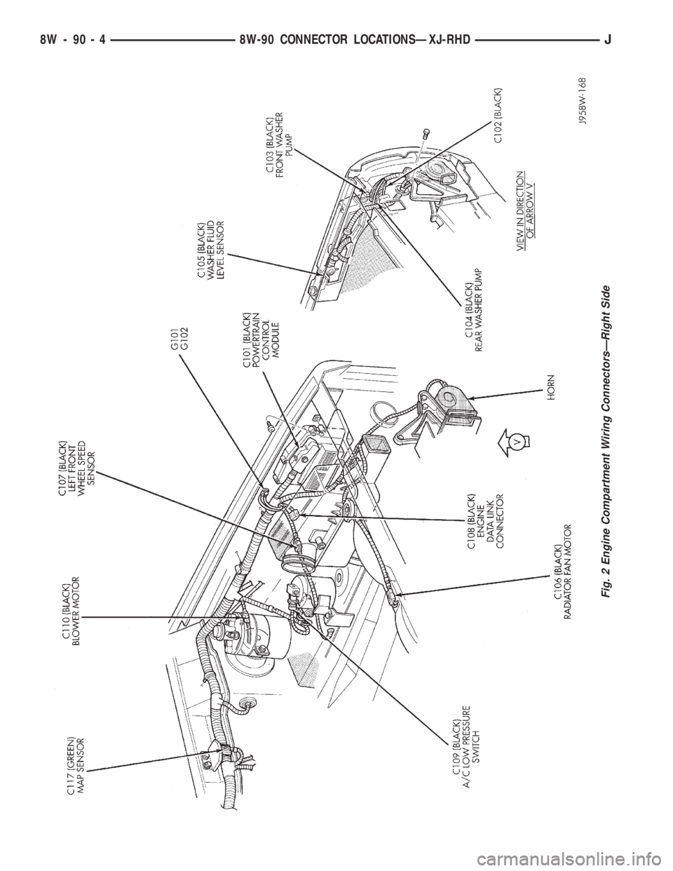
Fig. 2 Engine Compartment Wiring ConnectorsÐRight Side
8W - 90 - 4 8W-90 CONNECTOR LOCATIONSÐXJ-RHDJ