1995 JEEP XJ engine
[x] Cancel search: enginePage 625 of 2158

INSTRUMENT CLUSTER
INDEX
page page
ABS Warning Lamp........................ 2
Brake Warning Lamp....................... 2
Charging System Indicator Lamp............... 3
Cluster Ground............................ 3
Diagram Index............................. 3
Engine Coolant Temperature Gauge............ 1
Engine Coolant Temperature Warning Lamp...... 1
Fuel Gauge.............................. 1
High-Beam Indicator Lamp................... 2
Instrument Cluster......................... 1Low Fuel Warning Lamp..................... 1
Low Washer Fluid Warning Lamp.............. 2
Malfunction Indicator Lamp (MIL)............... 2
Manual Transmission Up-Shift Lamp............ 2
Oil Pressure Gauge........................ 2
Oil Pressure Warning Lamp.................. 2
Seat Belt Indicator Warning Lamp.............. 2
Speedometer............................. 2
Tachometer.............................. 2
Turn Signal Indicator Lamps.................. 2
INSTRUMENT CLUSTER
The instrument cluster contains the gauges and
warning lamps. All gauges have magnetic move-
ments.
When the ignition switch is in the START or RUN
position, circuit A21 feeds circuit F87 through fuse 17
in the fuse block. Circuit A1 from fuse 6 in the Power
Distribution Center (PDC) supplies voltage to circuit
A21. Circuit A1 is HOT at all times.
Circuit F87 connects to the cluster connector to
power the gauges and to the telltale connector to
power the warning lamps.
Circuit E2 from fuse 19 in the fuse block feeds the
illumination lamps. Circuit E2 originates at the head-
lamp switch and continues through fuse 19. The
headlamp switch powers circuit E2 when the parking
lamps or headlamp are ON.
Circuit Z2 provides ground for the indicator lamps
and illumination lamps.
ENGINE COOLANT TEMPERATURE GAUGE
Circuit G20 connects the engine coolant tempera-
ture gauge to the engine coolant temperature sensor.
The sensor is a variable resistor and case grounded to
the engine. Circuit F87 connects to the instrument
cluster left connector and supplies voltage for the
gauge.
The gauge uses two coils. Current passing through
the coils creates a magnetic field. Position of the
gauge needle is controlled by the amount of current
passing through the coils to ground at the sensor.
ENGINE COOLANT TEMPERATURE WARNING
LAMP
Circuit G20 connects the engine coolant tempera-
ture warning lamp to the engine coolant temperature
switch. When the switch closes, battery voltage from
circuit F87 flows through the lamp to ground through
the switch on circuit G20. The engine coolant tem-
perature switch is case grounded to the engine. Cir-cuit F87 connects to the instrument cluster connector
and supplies voltage for the lamp.
Circuit G20 also connects to the warning lamp to
ground when the ignition switch is in the START
position. When the ignition switch is in the START
position, the lamp illuminates for a bulb test.
FUEL GAUGE
The fuel level sensor is a variable resistor. Circuit
G4 connects the fuel level sensor to the fuel gauge in
the instrument cluster. Circuit F87 from fuse 17 in
the fuse block supplies voltage to the fuel gauge. The
fuel level sensor draws voltage from circuit F87
through the fuel gauge on circuit G4. Circuit G4
connects to circuit 57 in the fuel pump module har-
ness. Circuit 57 connects to the fuel level sensor.
Circuit 99 in the fuel pump module harness con-
nects to circuit Z1. Circuit Z1 provides the ground
path for the fuel level sensor. The grounding point for
circuit Z1 is the left side of the cowl panel.
As current flows through the coils in the fuel gauge,
it creates a magnetic field. One of the coils in the
gauge receives fixed current. The other coil is con-
nected to the level sensor. The magnetic field controls
the position of the fuel gauge pointer.
The fuel level sensor contains a variable resistor. As
the position of the float arm on the fuel level sensor
changes, the resistor changes the current flow
through second coil in the fuel gauge. A change in
current flow alters the magnetic field in the fuel
gauge, which changes the pointer position.
LOW FUEL WARNING LAMP
Circuit G4 connects the fuel level sensor to the fuel
gauge. The low fuel level module at the rear of the
gauge monitors resistance in circuit G4. The low fuel
level module powers an light emitting diode (LED)
when the resistance in circuit G4 reaches a calibrated
level. The LED illuminates the Low Fuel indicator.
Refer to Group 8E for additional information.
J8W-40 INSTRUMENT CLUSTERÐXJ VEHICLES 8W - 40 - 1
Page 626 of 2158

OIL PRESSURE GAUGE
The case grounded oil pressure sensor is a variable
resistor that connects to circuit G6. Circuit G6 con-
nects to the oil pressure gauge.
Circuit F87 connects to the instrument cluster con-
nector and supplies battery voltage to oil pressure
gauge. The gauge uses two coils. Current passing
through the coils creates a magnetic field. Position of
the gauge needle is controlled by the amount of cur-
rent passing through the coils to ground at the sen-
sor.
OIL PRESSURE WARNING LAMP
The case grounded oil pressure switch connects to
circuit G6. Circuit G6 connects to the oil pressure
warning lamp. Circuit F87 connects to the instru-
ment cluster connector and supplies battery voltage
to oil pressure lamp.
When the oil pressure switch close, battery voltage
flows through the warning lamp to ground through
the switch, illuminating the lamp.
TACHOMETER
The tachometer module in the instrument cluster
operates the tachometer. The Powertrain Control
Module (PCM) supplies the signal for the tachometer
on circuit G21. Circuit G21 connects to cavity 43 of
the PCM.
SPEEDOMETER
The speedometer and odometer receive a signal
from the vehicle speed sensor on circuit G7. Circuit
G7 also connects to the Powertrain Control Module
(PCM) at cavity 47.
ABS WARNING LAMP
Circuit F87 provides power for the ABS warning
lamp at the instrument cluster. Ground for the ABS
warning lamp is provided by either the ABS control
module or by the ABS power relay when the relay is
not energized. The ABS control module illuminates
the lamp by providing ground on circuit B205.
Circuit B205 splices to connect to circuit B235
through a diode. When the ABS power relay is not
energized, it connects circuit B235 to circuit Z12. The
ground path for the warning lamp is through the di-
ode to circuit B235, through the ABS power relay to
ground on circuit Z12.
The diode between circuit B205 and B235 prevents
voltage from flowing to the ABS control module when
the ABS power relay switches to supply power on cir-
cuit B235.
MALFUNCTION INDICATOR LAMP (MIL)
The PCM provides ground for the instrument clus-
ter malfunction indicator lamp on circuit G3. Circuit
G3 connects to cavity 32 of the PCM. Circuit F87provides voltage for the lamp. The MIL displays the
message CHECK ENGINE when illuminated.
For information regarding diagnostic trouble code
access using the MIL lamp, refer to Group 14, Fuel
Systems.
LOW WASHER FLUID WARNING LAMP
Circuit G29 connects the low washer fluid switch to
the warning lamp in the instrument cluster. Circuit
F12 supplies battery voltage to the switch.
When the low washer fluid switch closes, it con-
nects circuits G29 and F12. Battery voltage from cir-
cuit F12 powers the low washer fluid lamp. Circuit
Z1 at the instrument cluster provides ground to illu-
minate the warning lamp.
SEAT BELT INDICATOR WARNING LAMP
The seat belt indicator warning lamp is activated
by the chime/buzzer on circuit G11. Circuit G11 sup-
plies power to instrument cluster for the lamp. Cir-
cuit Z1 provides ground for the lamp at the cluster.
The chime/buzzer module powers circuit G11 after
it receives an input on circuit G10 indicating the seat
belt switch is open.
HIGH-BEAM INDICATOR LAMP
Circuit L3 supplies power for the high-beam indi-
cator lamp. The ground path for the lamp is through
circuit Z1. If the vehicle has Daytime Running
Lamps (DRL), the DRL module powers circuit L3
through circuit G465. On vehicles not equipped with
DRL, the headlamp switch powers circuit L3.
Circuit Z1 provides ground for the indicator lamp
at the cluster.
TURN SIGNAL INDICATOR LAMPS
Circuits L61 and L60 power for the turn signal in-
dicator lamps. Circuit L61 powers the left indicator
lamp. Circuit L60 powers the right indicator lamp.
Circuit Z1 provides ground for the lamps.
BRAKE WARNING LAMP
Circuit F87 supplies power to the park brake lamp.
Ground for the park brake lamp is supplied through
the case grounded park brake switch or brake warn-
ing switch on circuit G9. Circuit G9 Connects to cir-
cuit B203. Circuit B203 connects to the brake
warning lamp at the instrument cluster.
MANUAL TRANSMISSION UP-SHIFT LAMP
Circuit F87 supplies power for the manual trans-
mission up-shift lamp. The lamp illuminates when
the Powertrain Control Module (PCM) provides
ground for the lamp on circuit K54. Circuit K54 con-
nects to cavity 54 of the PCM.
8W - 40 - 2 8W-40 INSTRUMENT CLUSTERÐXJ VEHICLESJ
Page 627 of 2158
CHARGING SYSTEM INDICATOR LAMP
The Powertrain Control Module (PCM) illuminates
the charging system indicator lamp by providing
ground for the lamp on circuit G12. Circuit G12 con-
nects to cavity 36 of the PCM. Circuit F87 supplies
battery voltage to the lamp.
FOUR-WHEEL DRIVE (4WD) SWITCH
When the 4WD switch closes, circuit Z1 provides
ground for the 4WD indicator lamp in the instrument
cluster. Circuit F87 connects to the instrument clus-
ter and supplies battery voltage to the 4WD indicator
lamp. Circuit 107 connects the indicator lamp to the
4WD switch. Circuit 106 connects the lamp to the in-
strument cluster and circuit F87.
CLUSTER GROUND
Circuit Z1 from the instrument cluster left connec-
tor provides ground for the illumination lamps and
indicator lamps.
HELPFUL INFORMATION
²If the warning lamps don't operate, check fuse 14
in the fuse block.
²If the indicator lamps and illumination lamps
don't operate, check fuse 13 in the fuse block.
²Inspect the ground at the instrument panel lower
right reinforcement support.
DIAGRAM INDEX
Component Page
4WD Switch............................8W-40-9
4WD Indicator Lamp......................8W-40-9
ABS Control Module......................8W-40-9
Brake Warning Switch.....................8W-40-10
Chime/Buzzer Module......................8W-40-8
Daytime Running Lamps Module.............8W-40-5, 6
Engine Coolant Temperature Sending Unit.........8W-40-6
Engine Oil Pressure Sending Unit..............8W-40-6
Fuse 3 (PDC)...........................8W-40-8
Fuse 5 (PDC)...........................8W-40-4
Fuse 6 (PDC).........................8W-40-4, 8
Fuse 11 (PDC)..........................8W-40-8
Fuse 16 (PDC)..........................8W-40-8
Fuse 9 (Fuse Block).......................8W-40-8
Fuse 15 (Fuse Block)......................8W-40-4
Fuse 17 (Fuse Block)....................8W-40-4, 8
Fuse 19 (Fuse Block)......................8W-40-4
Headlamp Switch.......................8W-40-4, 5
Headlamp Delay Module....................8W-40-8
Headlamp Dimmer Switch...................8W-40-5
Ignition Switch......................8W-40-4, 8, 10
Instrument Cluster......................8W-40-4, 5
Low Washer Fluid Lamp Switch...............8W-40-8
Park Brake Switch.......................8W-40-10
Powertrain Control Module..................8W-40-6
Remote Keyless Entry Module................8W-40-8
Telltale Connector (Instrument Cluster).....8W-40-7 thru 10
J8W-40 INSTRUMENT CLUSTERÐXJ VEHICLES 8W - 40 - 3
Page 638 of 2158
AIR CONDITIONING/HEATER
CONTENTS
page page
A/C-HEATER SYSTEM...................... 1 HEATERSYSTEM......................... 1
GENERAL INFORMATION
This section of the wiring diagrams is divided into
two sub-sections; Heater, and A/C and Heater. When
referring to the circuit descriptions or wiring dia-
grams, ensure that you use the correct sub-section.
HEATER SYSTEM
BLOWER MOTOR
In the RUN or ACCESSORY position, the ignition
switch connects circuit A1 from fuse 6 in the Power
Distribution Center (PDC) to circuit A48. Circuit A48
supplies battery voltage to fuse 5 in the fuse block.
Fuse 5 supplies power to the heat mode switch on
circuit C7.
Circuit C43 from the heat mode switch splices to
supply voltage to the blower motor switch and the
blower motor resistor block. The blower motor switch
sets blower motor speed to HIGH, M1, M2, or LOW.
When the blower motor switch is in the LOW posi-
tion, circuit C43 from the heat mode supplies voltage
to the resistor block. Voltage does not pass through
the blower motor switch in the LOW position.In the M1 position, the blower motor switch sup-
plies voltage to the resistor block on circuit C4. From
circuit C4, voltage passes through three resistors in
the resistor block to the blower motor on circuit C1.
In the M2 position, the blower motor supplies volt-
age to the resistor block on circuit C6. From circuit
C6 voltage flows through two resistors to the blower
motor on circuit C1.
In the HIGH position, the blower motor switch con-
nects directly to the blower motor on circuit C1. Volt-
age does not pass through the resistor block.
Circuit Z1 provides ground for the blower motor.
A/C-HEATER SYSTEM
GENERAL INFORMATION
Several fuses supply power for the air conditioning/
heater system. In the START or RUN positions, the
ignition switch connects circuit A1 from fuse 6 in the
Power Distribution Center (PDC) to circuit A21. Cir-
cuit A21 powers a bus bar in the PDC that feeds cir-
cuit F12 through fuse 11. Circuit F12 feeds the
contact side of the A/C compressor clutch relay and
the coil side of the radiator fan relay (4.0L engine).
In the RUN or ACCESSORY position, the ignition
switch connects circuit A1 from fuse 11 in the PDC to
circuit A48. Circuit A48 supplies battery voltage to
fuse 5 in the fuse block. Fuse 5 supplies power to the
A/C-Heater control switch on circuit C7.
Fuse 13 in the PDC supplies battery voltage to the
contact side of the radiator fan relay on circuit F141.
Circuit A14 from fuse 15 in the PDC powers PDC
fuse 4.
BLOWER MOTOR
In the RUN or ACCESSORY position, the ignition
switch connects circuit A1 from fuse 6 in the PDC to
circuit A48. Circuit A48 supplies battery voltage to
fuse 5 in the fuse block. Fuse 5 supplies power to the
A/C-Heater control switch on circuit C7.
Circuit C43 from the A/C-heater switch splices to
supply voltage to the blower motor switch and the
blower motor resistor block. The blower motor switch
sets blower motor speed to HIGH, M1, M2, or LOW.
When the blower motor switch is in the LOW posi-
tion, circuit C43 from the A/C-Heater switch supplies
voltage to the resistor block. Voltage does not pass
through the blower motor switch in the LOW position
In the M1 position, the blower motor switch sup-
plies voltage to the resistor block on circuit C4. From
circuit C4, voltage passes through three resistors in
the resistor block to the blower motor on circuit C1.
J8W-42 AIR CONDITIONING/HEATERÐXJ VEHICLES 8W - 42 - 1
Page 639 of 2158
In the M2 position, the blower motor supplies volt-
age to the resistor block on circuit C6. From circuit
C6 voltage flows through two resistors to the blower
motor on circuit C1.
In the HIGH position, the blower motor switch con-
nects directly to the blower motor on circuit C1. Volt-
age does not pass through the resistor block.
Circuit Z1 provides ground for the blower motor.
AIR CONDITIONING OPERATION
When the A/C-heater control switch is moved to an
A/C position or the defrost position, the Powertrain
Control Module (PCM) receives the A/C select signal
on circuit C90. Circuit C90 connects to cavity 28 of
the PCM.
Circuit also C90 splices to the low pressure switch
and to supply battery voltage to the coil side of the
A/C compressor clutch relay. If the low pressure
switch is closed, circuit C90 connects to circuit C21.
Circuit C21 supplies battery voltage to the A/C cy-
cling switch. Circuit C91 from the A/C cycling switch
provides the A/C request signal to the PCM. Circuit
C91 connects to cavity 27 of the PCM. Circuit Z1 pro-
vides ground for the A/C cycling switch.
After receiving the A/C request signal, the PCM
supplies ground for the A/C compressor clutch relay
on circuit C13. Circuit F12 from fuse 11 in the PDC
supplies battery voltage to the contact side of the A/C
compressor clutch relay. When the PCM grounds the
relay, the contacts close and connect circuit F12 to
circuit C3. Circuit C3 feeds the A/C compressor
clutch.
Also, after receiving the A/C request signal, the
PCM supplies ground for the coil side of the radiator
fan relay on circuit C27 (4.0L engine). Circuit C27
connects to cavity 31 of the PCM. Circuit F12 sup-
plies battery voltage to the coil side of the relay.
When the PCM grounds the coil side of the radia-
tor fan relay, the contacts close and connects circuit
F141 from fuse 4 in the PDC to circuit C25. Circuit
C25 feeds the radiator fan motor. Circuit Z1 provides
ground for the motor.
HELPFUL INFORMATION
Circuit A14 from PDC fuse 2 powers circuit F141
through fuse 15 in the PDC.
RADIATOR FAN RELAY AND MOTOR
In the START or RUN positions, the ignition
switch connects circuit A1 from fuse 6 in the Power
Distribution Center (PDC) to circuit A21. Circuit A21
powers a bus bar in the PDC that feeds circuit F12
through fuse 11. Circuit F12 feeds the coil side of the
radiator fan relay (4.0L engine).
The PCM supplies ground for the coil side of the
radiator fan relay on circuit C27 (4.0L engine). Cir-
cuit C27 connects to cavity 31 of the PCM.
When the PCM grounds the coil side of the radia-
tor fan relay, the contacts close and connects circuit
F141 from fuse 15 in the PDC to circuit C25. Circuit
C25 feeds the radiator fan motor. Circuit Z1 provides
ground for the radiator fan motor.
HELPFUL INFORMATION
Circuit A14 from PDC fuse 2 powers circuit F141
through fuse 15 in the PDC.
DIAGRAM INDEX
Component Page
A/C Compressor Clutch.....................8W-42-4
A/C Compressor Clutch Relay................8W-42-4
A/C Cycling Switch.......................8W-42-4
A/C Low Pressure Switch...................8W-42-4
A/C Mode Select Switch....................8W-42-5
Blower Motor...........................8W-42-3
Blower Motor Switch......................8W-42-3
Blower Motor Resistor.....................8W-42-3
Fuse 2 (PDC)...........................8W-42-5
Fuse 5 (Fuse Block).....................8W-42-3, 5
Fuse 6 (PDC).........................8W-42-3, 5
Fuse 11 (PDC)..........................8W-42-4
Fuse 15 (PDC)..........................8W-42-5
Heater Mode Switch.......................8W-42-3
Ignition Switch......................8W-42-3, 4, 5
Powertrain Control Module..................8W-42-4
Radiator Fan Motor.......................8W-42-5
Radiator Fan Relay.......................8W-42-5
8W - 42 - 2 8W-42 AIR CONDITIONING/HEATERÐXJ VEHICLESJ
Page 785 of 2158
CONNECTOR LOCATIONS
GENERAL INFORMATION
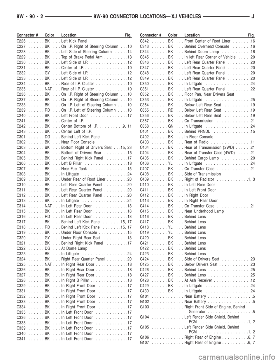
This section provides illustrations identifying com-
ponent and connector locations in the vehicle. A con-nector index is provided. Use the wiring diagrams in
each section for connector number identification. Re-
fer to the index for the proper figure number.
CONNECTOR LOCATIONS
Connector # Color Location Fig.
C101......BK ...Front of Left Fender Side Shield . . .1, 2
C102......BK ...Bottom Right of Radiator Closure
Panel....................8
C103......BK ...Near Left Side of Radiator......2,8
C104......BK ...Left Fender Side Shield
C105......BK ...Bottom of Left Fender Side Shield . . .2
C106......BK ...Left Fender Side Shield, Near PCM .1, 2
C107......BK ...OnABSPump Motor...........2
C108......BK ...Right Rear Corner of Engine
Compartment.............2,3
C109......BK ...Center of Dash Panel.........1,4
C110......BK ...Center of I.P., Below ABS Control
Module...............13, 14
C111......BK ...Left of Steering Column.........14
C112......BK ...AtABSControl Module.........13
C113......BK ...InHarness, Near ABS Control
Module.................13
C114......BK ...Center of I.P., Below ABS Control
Module.................14
C115......BK ...Near ABS Control Module.......14
C116......BK ...Below ABS Control Module.......14
C117......BK ...Rear of Intake Manifold........6,7
C118......BK ...OnThrottle Body............6,7
C119......BK ...Bottom Left Front of Cylinder
Block..................6,7
C120......BK ...OnThrottle Body............6,7
C121......GY ...Rear of Intake Manifold........6,7
C122......BK ...AtThermostat Housing........6,7
C123......BK ...Injector No. 1..............6,7
C124......BK ...Injector No. 2..............6,7
C125......BK ...Injector No. 3..............6,7
C126......BK ...Injector No. 4..............6,7
C127......BK ...Injector No. 5................7
C128......BK ...Injector No. 6................7
C129......GN ...Center of Dash Panel.........1,4
C130......BK ...Below Brake Master Cylinder.....1,2
C131......BK ...Distributor................6,7
C132......GN ...Lower Right Side of I.P.
C133......BK ...Right of Blower Motor..........4
C134......GY ...Right of Blower Motor..........4
C135......GY ...Right of Blower Motor..........4
C136......BR ...OnWasher Fluid Reservoir......1,4
C137......BK ...Under Side of Hood..........1,4
C138......BK ...Left of Blower Motor...........4
C139......BK ...Bottom of Washer Fluid Reservoir .3, 4
C140......BK ...Bottom of Washer Fluid Reservoir .3, 4
C141......BK ...InFront of Washer Fluid Reservoir .1, 4
C142......BK ...Between PDC and Blower Motor . .1, 4Connector # Color Location Fig.
C143......BK ...Bottom Front of Right Fender
Side Shield..............1,3
C144......BK ...Front of Right Fender Side Shield . .1, 3
C145......BK ...Front of Right Fender Side Shield . .1, 3
C146......BK ...Right Side of Grille Opening.....1,3
C147......BK ...Below Distributor..............7
C148......BK ...Right Side of Engine..........6,7
C149......BK ...Rear of Generator...........5,6
C150......BK ...Right Rear of Engine...........7
C151......BK ...Right Fender Side Shield.......1,4
C152......GY ...Behind Power Steering Pump......6
C153......BK ...Right Side of Transmission.......21
C154......BK ...Left Side of Radiator Closure Panel . .8
C155......BK ...Left Rear of Radiator Closure Panel . .8
C156......BK ...Behind Lens.................8
C157......BK ...Behind Left Headlamp...........8
C158......BK ...Behind Lens.................8
C159......BK ...Center of Grille Opening.........8
C160......BK ...Behind Lens.................8
C161......BK ...Behind Right Headlamp..........8
C162......BK ...Behind Lens.................8
C163......BK ...Center of Grille Opening.........8
C164......BK ...Right Center of Engine Compartment
C201......BK ...Below Left Side of I.P.........9,14
C202......LG ...Behind Left Kick Panel.........14
C203......BK ...Behind Left Kick Panel.........14
C204......GY ...Behind Left Kick Panel.........14
C205......BK ...Bottom Right of I.P............12
C206......BK ...Bottom Right of I.P............12
C207......BK ...Behind Headlamp Switch........10
C208......BK ...Bottom Right of I.P............12
C209......BK ...OnI.P.Right of Steering Column . . .10
C210......BK ...OnI.P.Right of Steering Column . . .10
C211......BK ...Rear of Radio...............11
C212......BR ...Center of I.P.................10
C213......BK ...Center of I.P.................10
C214......GY ...Right Side of I.P..............13
C215......BK ...Right Side of I.P..............13
C216......GY ...Glove Box.................10
C217......BK ...Bottom Right of I.P............11
C218......RD ...Right Side of I.P...........13, 17
C219......BK ...Bottom Right of I.P............11
C220......BK ...Right Side of I.P..............13
C221......BK ...Right Corner of I.P............13
C222......LG ...Right Corner of I.P............13
C223......BK ...Right Front of Steering Column....14
C224......BK ...Right Front of Steering Column....14
C225......NAT...Below Steering Column.........14
J8W-90 CONNECTOR LOCATIONSÐXJ VEHICLES 8W - 90 - 1
Page 786 of 2158
Connector # Color Location Fig.
C226......BK ...Left Kick Panel
C227......BK ...OnI.P.Right of Steering Column . . .10
C228......BK ...Left Side of Steering Column.....14
C229......BK ...TopofBrake Pedal Arm.........13
C230......BK ...Left Side of I.P...............12
C231......BK ...Center of I.P.................10
C232......GY ...Left Side of I.P...............12
C233......BK ...Left Side of I.P...............12
C234......BK ...Rear of I.P. Cluster............10
C235......NAT...Rear of I.P. Cluster............10
C236......BK ...OnI.P.Right of Steering Column . . .10
C237......BK ...OnI.P.Right of Steering Column . . .10
C238......BK ...OnI.P.Left of Steering Column....10
C239......RD ...OnI.P.Left of Steering Column....10
C240......BK ...Left Front Door..............17
C241......BK ...Center of I.P.
C242......BK ...Center Bottom of I.P..........9,11
C243......BK ...Center Left of I.P.
C301......DG ...Behind Left Kick Panel
C302......BK ...Near Floor Console
C303......BK ...Bottom Right of Drivers Seat . . .15, 23
C304......BK ...Bottom of Drivers Sear.........15
C305......BK ...Behind Right Kick Panel........17
C306......BK ...Left B Pillar................18
C307......BK ...Near Fuel Tank..............15
C308......BK ...InLiftgate.................24
C309......BK ...Under Rear of Roof Liner........20
C310......BK ...Left Rear Quarter Panel.........20
C311......BK ...Left Rear Quarter Panel.........20
C312......BK ...Left Rear Quarter Panel.........20
C313......BK ...InLiftgate.................24
C314......NAT...InLeft Rear Door.............18
C315......BK ...InLeft Rear Door.............18
C316......RD ...InLeft Rear Door.............18
C317......BK ...Behind Left Kick Panel.......15, 17
C318......RD ...Behind Left Kick Panel.......15, 17
C319......BK ...Under Floor Console...........15
C320......GY ...Under Right Rear Seat.........18
C321......BK ...Behind Right Kick Panel........17
C322......DG ...AtDome Lamp
C323......BK ...InLiftgate.................24
C324......BK ...Right Rear Quarter Panel........20
C325......NAT...InRight Rear Door............18
C326......BK ...InRight Rear Door............18
C327......BK ...InRight Rear Door............18
C328......BK ...InRight B Pillar..............18
C329......BK ...InRight Front Door...........17
C331......BK ...InRight Front Door...........17
C332......BK ...InRight Front Door...........17
C333......BK ...InRight Front Door...........17
C334......BK ...InRight Front Door...........17
C335......BK ...InLeft Front Door............17
C336......BK ...InLeft Front Door............17
C338......BK ...InLeft Front Door............17
C339......BK ...InLeft Front Door............17
C340......BK ...InLeft Front Door............17
C341......BK ...InLeft Front Door............17Connector # Color Location Fig.
C342......BK ...Front Center of Roof Liner.......16
C343......BK ...Behind Overhead Console.......16
C344......BK ...Behind Doom Lamp...........16
C345......BK ...Inleft Rear Corner of Vehicle.....20
C346......BK ...Left Rear Quarter Panel.........20
C347......BK ...Left Rear Quarter Panel.........20
C348......BK ...Left Rear Quarter Panel.........20
C349......BK ...Left Rear Quarter Panel.........20
C350......BK ...InLiftgate.................24
C351......BK ...Left Rear Quarter Panel.........22
C352......BK ...Floor Pan, Near Drivers Seat
C353......BK ...InLiftgate.................25
C354......BK ...Below Left Rear Seat..........19
C355......RD ...Below Left Rear Seat..........19
C356......BK ...Below Left Rear Seat..........19
C357......BK ...OnTransmission.............21
C358......GN ...InLiftgate.................24
C401......BK ...Behind PRNDL..............15
C402......BK ...InFloor Console
C403......BK ...Rear of Radio...............11
C404......BK ...Rear of Transmission (2WD)......21
C404......BK ...Rear of Transfer Case (4WD).....21
C405......BK ...Behind Cargo Lamp...........20
C406......YL ...InLiftgate.................24
C407......BK ...OnTransfer Case.............21
C408......BK ...Side of Transmission
C409......BK ...Right of Radiator............1,3
C410......BK ...InLeft Rear Door
C411......BK ...InLeft Front Door
C412......BK ...InRight Door
C413......BK ...InRight Rear Door
C414......BK ...OnTransfer Case.............21
C415......BK ...Near Underhood Lamp
C416......BK ...Behind Lens
C417......BK ...Behind Lens
C418......YL ...Behind Lens
C419......YL ...Behind Lens
C420......BK ...Behind Lens
C421......BK ...Behind Lens
C422......BK ...Behind Lens
C423......BK ...Behind Lens
C424......BK ...Side of Drivers Seat...........23
C425......BK ...Below Drivers Seat............23
C426......BK ...Behind Lens................25
C427......BK ...Behind Lens................25
C428......BK ...AtAshReceiver..............12
C429......BK ...InLiftgate.................24
C430......BK ...InLiftgate.................24
G101............Near Battery.................5
G102............Near Battery.................5
G103............Right Front Side of Engine, Behind
Generator.................5
G104............Left Fender Side Shield, Behind
PCM ..................1,2
G105............Left Fender Side Shield, Behind
PCM ..................1,2
G106............Right Rear of Engine..........6,7
G107............Right Rear of Engine..........6,7
8W - 90 - 2 8W-90 CONNECTOR LOCATIONSÐXJ VEHICLESJ
Page 787 of 2158
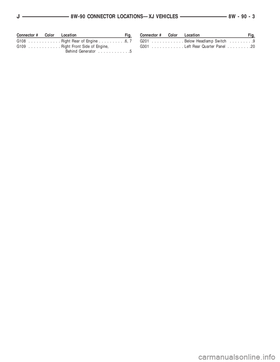
Connector # Color Location Fig.
G108............Right Rear of Engine..........6,7
G109............Right Front Side of Engine,
Behind Generator............5Connector # Color Location Fig.
G201............Below Headlamp Switch.........9
G301............Left Rear Quarter Panel.........20
J8W-90 CONNECTOR LOCATIONSÐXJ VEHICLES 8W - 90 - 3