1995 JEEP CHEROKEE capacities
[x] Cancel search: capacitiesPage 2 of 2198
LUBRICATION AND MAINTENANCE
CONTENTS
page page
CHASSIS AND BODY COMPONENTS........ 28
DRIVETRAIN........................... 22
ENGINE MAINTENANCE................... 15GENERAL INFORMATION.................. 1
JUMP STARTING, TOWING AND HOISTING.... 9
MAINTENANCE SCHEDULES................ 4
GENERAL INFORMATION
INDEX
page page
Classification of Lubricants................... 2
Components Requiring No Lubrication........... 2
Fluid Capacities........................... 3
Fuel Requirements......................... 1International Symbols....................... 1
Introduction.............................. 1
Lubrication and Replacement Parts
Recommendation......................... 2
INTRODUCTION
Lubrication and maintenance is divided into re-
quired and recommended service tasks. The required
service tasks must be completed to verify the emis-
sion controls function correctly. The recommended
service tasks should be completed to maintain safety
and durability.
This information will assist the service personnel
in providing maximum protection for each owner's
vehicle.
Conditions can vary with individual driving habits.
It is necessary to schedule maintenance as a time in-
terval as well as a distance interval.
It is the owner's responsibility to determine the ap-
plicable driving condition. Also to have the vehicle
serviced according to the maintenance schedule, and
to pay for the necessary parts and labor.
Additional maintenance and lubrication informa-
tion is listed in the Owner's Manual.
INTERNATIONAL SYMBOLS
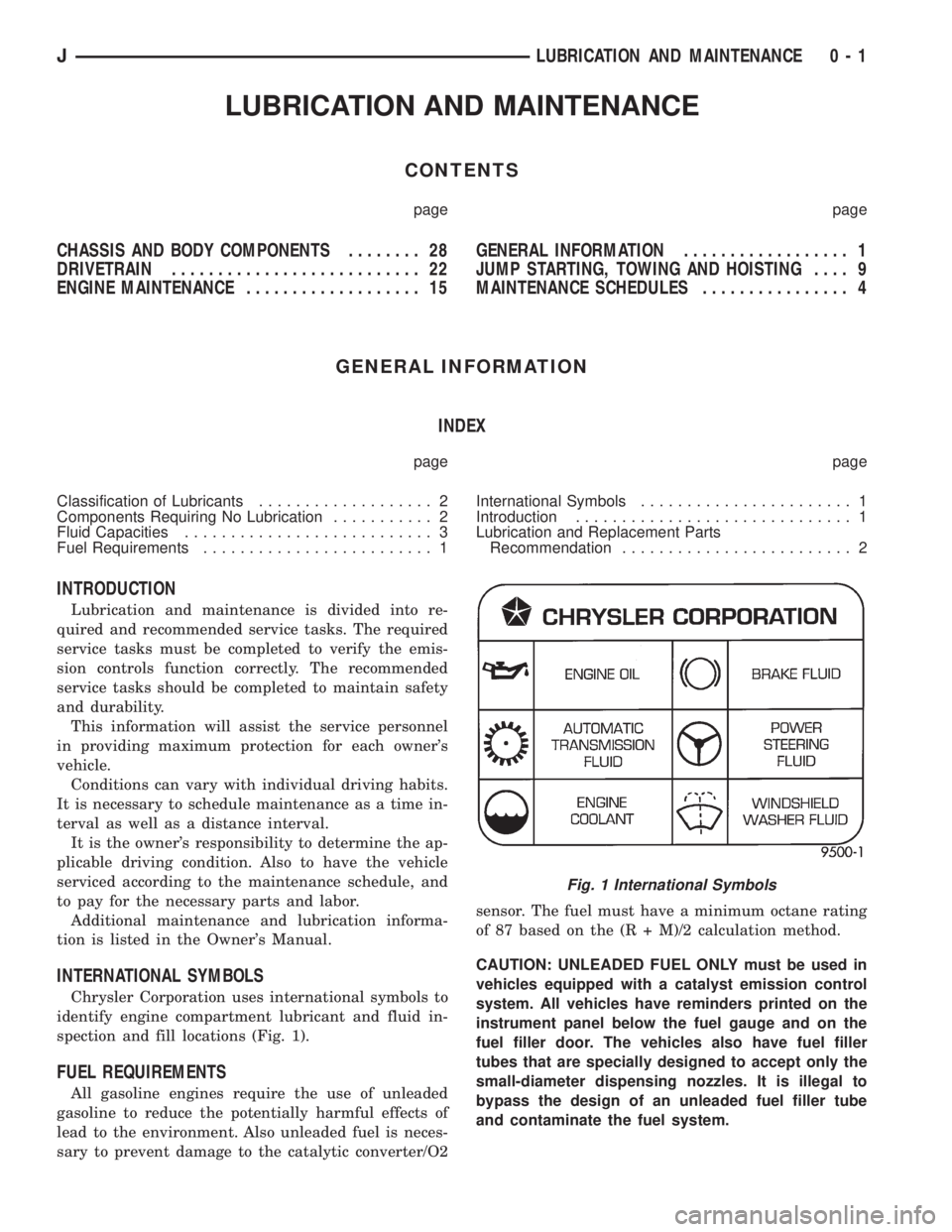
Chrysler Corporation uses international symbols to
identify engine compartment lubricant and fluid in-
spection and fill locations (Fig. 1).
FUEL REQUIREMENTS
All gasoline engines require the use of unleaded
gasoline to reduce the potentially harmful effects of
lead to the environment. Also unleaded fuel is neces-
sary to prevent damage to the catalytic converter/O2sensor. The fuel must have a minimum octane rating
of 87 based on the (R + M)/2 calculation method.
CAUTION: UNLEADED FUEL ONLY must be used in
vehicles equipped with a catalyst emission control
system. All vehicles have reminders printed on the
instrument panel below the fuel gauge and on the
fuel filler door. The vehicles also have fuel filler
tubes that are specially designed to accept only the
small-diameter dispensing nozzles. It is illegal to
bypass the design of an unleaded fuel filler tube
and contaminate the fuel system.
Fig. 1 International Symbols
JLUBRICATION AND MAINTENANCE 0 - 1
Page 4 of 2198
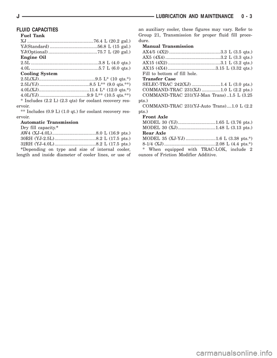
FLUID CAPACITIES
Fuel Tank
XJ .....................................................76.4 L (20.2 gal.)
YJ(Standard) ......................................56.8 L (15 gal.)
YJ(Optional) .......................................75.7 L (20 gal.)
Engine Oil
2.5L ......................................................3.8 L (4.0 qts.)
4.0L ......................................................5.7 L (6.0 qts.)
Cooling System
2.5L(XJ).............................................9.5 L* (10 qts.*)
2.5L(YJ) ........................................8.5 L** (9.0 qts.**)
4.0L(XJ) ........................................11.4 L* (12.0 qts.*)
4.0L(YJ) ......................................9.9 L** (10.5 qts.**)
* Includes (2.2 L) (2.3 qts) for coolant recovery res-
ervoir.
** Includes (0.9 L) (1.0 qt.) for coolant recovery res-
ervoir.
Automatic Transmission
Dry fill capacity.*
AW4 (XJ-4.0L) ...................................8.0 L (16.9 pts.)
30RH (YJ-2.5L) .................................8.2 L (17.5 pts.)
32RH (YJ-4.0L) .................................8.2 L (17.5 pts.)
*Depending on type and size of internal cooler,
length and inside diameter of cooler lines, or use ofan auxiliary cooler, these figures may vary. Refer to
Group 21, Transmission for proper fluid fill proce-
dure.
Manual Transmission
AX4/5 (4X2) .........................................3.3 L (3.5 qts.)
AX5 (4X4) ............................................3.2 L (3.3 qts.)
AX15 (4X2) ..........................................3.1 L (3.2 qts.)
AX15 (4X4) ......................................3.15 L (3.32 qts.)
Fill to bottom of fill hole.
Transfer Case
SELEC-TRAC 242(XJ) .......................1.4 L (3.0 pts.)
COMMAND-TRAC 231(XJ) ...............1.0 L (2.2 pts.)
COMMAND-TRAC 231(YJ-Man Trans) ..1.5 L (3.25
pts.)
COMMAND-TRAC 231(YJ-Auto Trans) ....1.0 L (2.2
pts.)
Front Axle
MODEL 30 (YJ) ..............................1.65 L (3.76 pts.)
MODEL 30 (XJ) ..............................1.48 L (3.13 pts.)
Rear Axle
MODEL 35 (XJ-YJ) ........................1.6 L (3.38 pts.*)
8-1/4 (XJ) .........................................2.08 L (4.4 pts.*)
* When equipped with TRAC-LOK, include 2
ounces of Friction Modifier Additive.
JLUBRICATION AND MAINTENANCE 0 - 3
Page 270 of 2198
SPECIFICATIONS
GENERAL INFORMATION
The following specifications are published from the
latest information available at the time of publica-
tion.If anything differs between the specifica-
tions found on the Vehicle Emission Control
Information (VECI) label and the following
specifications, use specifications on VECI label.
The VECI label is located in the engine compart-
ment.
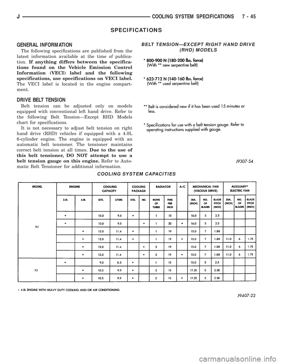
DRIVE BELT TENSION
Belt tension can be adjusted only on models
equipped with conventional left hand drive. Refer to
the following Belt TensionÐExcept RHD Models
chart for specifications.
It is not necessary to adjust belt tension on right
hand drive (RHD) vehicles if equipped with a 4.0L
6-cylinder engine. The engine is equipped with an
automatic belt tensioner. The tensioner maintains
correct belt tension at all times.Due to the use of
this belt tensioner, DO NOT attempt to use a
belt tension gauge on this engine.Refer to Auto-
matic Belt Tensioner for additional information.
COOLING SYSTEM CAPACITIES
BELT TENSIONÐEXCEPT RIGHT HAND DRIVE
(RHD) MODELS
JCOOLING SYSTEM SPECIFICATIONS 7 - 45
Page 1228 of 2198
FUEL TANKS
INDEX
page page
Fuel Gauge Sending Unit................... 16
Fuel Tank............................... 13
Fuel Tank Capacities....................... 13
Fuel Tank Filler Tube Cap................... 13Fuel Tank Pressure Relief/Rollover Valve........ 16
General Information....................... 13
Heat Shields............................. 13
No-Lead Fuel Tank Filler Tube................ 13
GENERAL INFORMATION
All XJ and YJ models pass a full 360 degree roll-
over test without fuel leakage. To accomplish this,
fuel and vapor flow controls are required for all fuel
tank connections.
All models are equipped with a pressure relief/roll-
over valve mounted in the top of the fuel tank. The
return line from the fuel pump to the fuel tank con-
tains a one-way check valve.
An evaporative control system prevents raw fuel
vapor from escaping into the atmosphere. Fuel va-
pors from the fuel tank are collected in the EVAP
canister. When the engine is operating, the vapors
are drawn into the intake manifold to be used in
combustion. Refer to Group 25, Emission Control
System for more information.
Inspect all hose/tube connections for completeness.
Be sure that leaks are not present. Replace any hose
that is cracked, scuffed, swelled, has rubbed against
other vehicle components or shows any other sign of
wear that could lead to failure. If it is necessary to
replace a hose, only hose marked EFM/EFI may be
used.
When installing hoses, be sure that they are routed
away from contact with other vehicle components.
The hose clamps used on fuel injected vehicles are
of a special rolled edge construction to prevent the
edge of the clamp from cutting into the hose. Only
these rolled edge type clamps may be used on this
system. Other types of clamps may cut into the hoses
and cause high-pressure fuel leaks.
FUEL TANK CAPACITIES
Refer to the Specifications section at the end of this
group.
NO-LEAD FUEL TANK FILLER TUBE
All vehicles are designed to operate using Unleaded
fuels. The diameter of the opening in the fuel tank
filler neck is sized to only accept unleaded fuel noz-
zles. Gasoline station pumps for unleaded and leaded
fuels have different size nozzles. Leaded fuel nozzles
are larger in diameter than unleaded nozzles. The
fuel tank filler neck opening is also equipped with adeflector, which the smaller unleaded nozzle pushes
back upon entering the filler neck. The deflector will
prevent the larger diameter leaded fuel nozzles from
entering the filler neck and will deflect fuel away
from the filler neck. This happens if filling of the
tank with leaded fuel is attempted.
A label is attached to the instrument panel under
the fuel gauge that reads UNLEADED FUEL ONLY
as a reminder to the driver. A similar label is located
near the fuel tank filler.
FUEL TANK FILLER TUBE CAP
The loss of any fuel or vapor out of the filler neck
is prevented by the use of a safety filler cap. This
will release only under pressure of 10.9 to 13.45 kPa
(1.58 to 1.95 psi). The vacuum release is between .97
and 2.0 kPa (.14 and .29 psi). This cap must be re-
placed by a similar unit if replacement is necessary.
CAUTION: Remove the fuel tank filler tube cap prior
to removing or repairing fuel lines to relieve fuel
tank pressure.
HEAT SHIELDS
The sheet metal heat shields may have to be re-
moved when servicing the fuel tank, fuel lines or va-
por vent line. The heat shields must be installed to
protect the lines and tank from the heat of the ex-
haust system. Refer to Group 11, Exhaust System
and Intake Manifold for proper installation.
FUEL TANK
WARNING: THE FUEL SYSTEM IS UNDER CON-
STANT FUEL PRESSURE (EVEN WITH THE ENGINE
OFF) OF APPROXIMATELY 131-269 KPA (19-39 PSI).
THIS PRESSURE MUST BE RELEASED BEFORE
SERVICING FUEL TANK.
REMOVALÐXJ MODELS
Perform the preceding Fuel System Pressure Re-
lease Procedure.
(1) Disconnect negative battery cable.
JFUEL TANKS 14 - 13
Page 1282 of 2198
speedometer pinion gear adapter (Fig. 29). Do not re-
move the gear adapter from the transmission.
INSTALLATION
(1) Clean the inside of speedometer pinion gear
adapter before installing speed sensor.
(2) Install sensor into speedometer gear adapter
and install mounting bolt.Before tightening bolt,verify speed sensor is fully seated (mounted
flush) to speedometer pinion gear adapter.
(3) Tighten sensor mounting bolt to 2.2 Nzm (20 in.
lbs.) torque.
(4) Connect electrical connector to sensor.
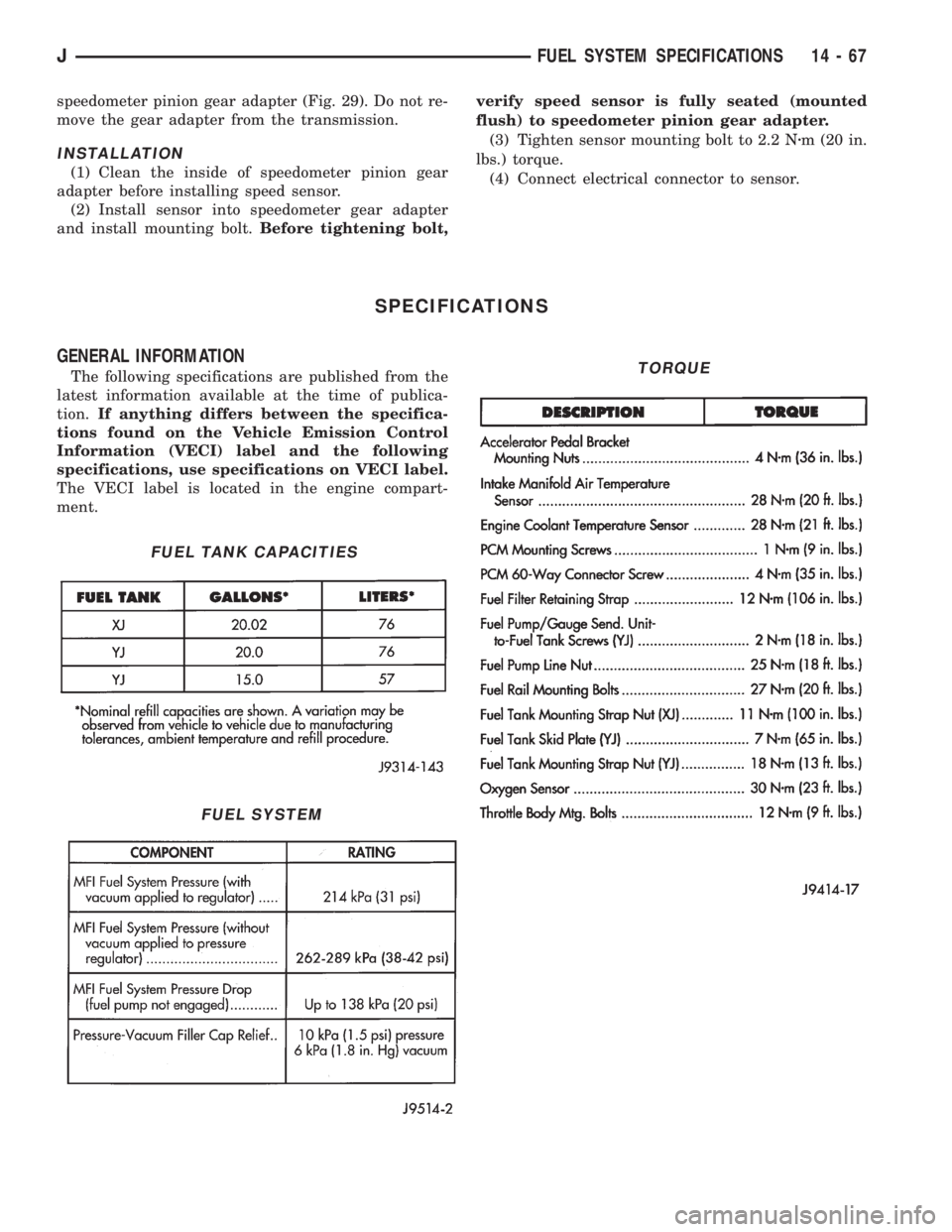
SPECIFICATIONS
GENERAL INFORMATION
The following specifications are published from the
latest information available at the time of publica-
tion.If anything differs between the specifica-
tions found on the Vehicle Emission Control
Information (VECI) label and the following
specifications, use specifications on VECI label.
The VECI label is located in the engine compart-
ment.
FUEL TANK CAPACITIES
FUEL SYSTEM
TORQUE
JFUEL SYSTEM SPECIFICATIONS 14 - 67
Page 1722 of 2198
WHEELS AND TIRES
CONTENTS
page page
SPECIFICATIONS........................ 12
TIRES.................................. 1VEHICLE VIBRATION..................... 10
WHEELS................................ 6
TIRES
INDEX
page page
Cleaning of Tires.......................... 2
General Information........................ 1
Pressure Gauges.......................... 2
Repairing Leaks........................... 3
Replacement Tires......................... 2Rotation................................. 3
Tire Inflation Pressures...................... 2
Tire Noise or Vibration...................... 4
Tire Wear Patterns......................... 4
Tread Wear Indicators....................... 3
GENERAL INFORMATION
Tires are designed for each specific vehicle. They
provide the best overall performance for normal oper-
ation. The ride and handling characteristics match
the vehicle's requirements. With proper care they
will give excellent reliability, traction, skid resis-
tance, and tread life. These tires have specific load
carrying capacities. When correctly inflated, they will
operate properly.
Tires used in cool climates, and with light loads
will have a longer life than tires used in hot climates
with heavy loads. Abrasive road surfaces will acceler-
ate tire wear.
Driving habits have more effect on tire life than
any other factor. Careful drivers will obtain much
greater mileage than careless drivers.
Driving habits that shorten the life of any tire;
²Rapid acceleration and deceleration
²Severe application of brakes
²High-speed driving
²Taking turns at excessive speeds
²Striking curbs and other obstacles
It is very important to follow the tire rotation in-
terval
IDENTIFICATION
Tire type, size, aspect ratio and speed rating are
encoded in the letters and numbers imprinted on the
side wall of the tire. Refer to the chart to decipher
the tire identification code (Fig. 1).Performance tires will have a speed rating letter
after the aspect ratio number. The speed rating is not
always printed on the tire sidewall. The letterSin-
dicates that the tire is speed rated up to 112 mph.
²Qup to 100 mph
²Tup to 118 mph
²Uup to 124 mph
²Hup to 130 mph
²Vup to 149 mph
²Zmore than 149 mph (consult the tire manufac-
turer for the specific speed rating)
An All Season type tire will have eitherM+S,M
&SorMÐS(indicating mud and snow traction) im-
printed on the side wall.
RADIAL-PLY TIRES
Radial-ply tires improve handling, tread life, ride
quality and decrease rolling resistance.
Radial-ply tires must always be used in sets of
four. Under no circumstances should they be used on
the front only. They may be mixed with temporary
spare tires when necessary, but reduced speeds are
recommended.
Radial-ply tires have the same load-carrying capac-
ity as other types of tires of the same size. They use
the same recommended inflation pressures.
SPARE TIRE (TEMPORARY)
The compact spare tire is designed for emergency
use only. The original tire should be repaired and re-
installed at the first opportunity. Refer to Owner's
Manual for complete details.
JWHEELS AND TIRES 22 - 1
Page 1906 of 2198
REFRIGERANT SERVICE AND PERFORMANCE TEST
INDEX
page page
Air Conditioning Performance Tests............ 12
Charging Refrigerant System................. 11
Evacuating Refrigerant System............... 11Leak Testing Refrigerant.................... 11
Recovering Refrigerant System............... 11
Refrigerant Oil........................... 12
LEAK TESTING REFRIGERANT
REVIEW WARNINGS AND CAUTIONS IN
THIS GROUP BEFORE LEAK TESTING.
If A/C system is not cooling properly, determine if
system is fully charged. Refer to Refrigerant System
Diagnosis Chart. If the system is empty evacuate the
A/C system and charge system with 0.283 kPa (0.6
lbs. or 10 oz.) R-134a refrigerant. Refer to Charging
Refrigerant System for instructions. To detect a leak
in the system, perform the following procedures.
(1) Position the vehicle in a wind free work area.
This will aid in detecting small leaks.
(2) Bring A/C system up to operating temperature
and pressure. This is done by allowing the engine to
run with the A/C on for 5 to 7 minutes.
(3) Open hood 5 minutes prior to leak test. This
will dissipate any accumulated refrigerant in the en-
gine compartment.
(4) With the engine not running, use an R-134a
Electronic Leak Detector and search for leaks. Move
probe slowly along the bottom side of lines and fit-
tings, because R-134a is heavier than air. Fittings,
lines, or components that appear to be oily usually
indicates a refrigerant leak.
(5) To inspect the evaporator core for leaks. Set the
blower at low speed and the selector in PANEL and
RECIRC mode check for leaks at CENTER panel out-
lets.
RECOVERING REFRIGERANT SYSTEM
REVIEW WARNINGS AND CAUTIONS IN
GENERAL INFORMATION SECTION OF THIS
GROUP BEFORE DISCHARGING SYSTEM.
R-134a refrigerant is a hydrofluorocarbon (HFC)
that does not contain chlorine. R-134a refrigerant Re-
covery/Recycling Station that meets SAE standard
J2210 must be used to recover the refrigerant. Refer
to the operating instructions provided with the equip-
ment for proper operation.
EVACUATING REFRIGERANT SYSTEM
REVIEW WARNINGS AND CAUTIONS IN
GENERAL INFORMATION SECTION OF THIS
GROUP BEFORE EVACUATING SYSTEM.
If the A/C system has been open to the atmosphere,
it must be evacuated before the system can be
charged. Moisture and air mixed with refrigerant will
raise the compressor head pressure above acceptable
operating levels. This will reduce the performance of
the air conditioner and damage the compressor. Mois-
ture will boil at near room temperature when ex-
posed to vacuum. To evacuate the refrigerant system
use following procedure:
(1) Connect a suitable charging station and mani-
fold gauge set to the vehicle.
(2) Open the low and high side valves and start
vacuum pump. When suction gauge reads 88 kPa (26
in. Hg) vacuum or greater, close all valves and turn
off vacuum pump. If system fails to reach specified
vacuum, the system has a leak that must be cor-
rected. If system maintains the specified vacuum for
30 minutes, start the vacuum pump. Then open the
suction and discharge valves and evacuate an addi-
tional 10 minutes.
(3) Close all valves. Turn off and disconnect the
vacuum pump.
The system is now ready to be charged with refrig-
erant.
CHARGING REFRIGERANT SYSTEM
REVIEW WARNINGS AND CAUTIONS IN
GENERAL INFORMATION SECTION OF THIS
GROUP BEFORE CHARGING SYSTEM.
After the system has been tested for leaks and
evacuated, a refrigerant charge can be injected into
the system. Refer to refrigerant capacities for proper
amount of refrigerant charge. Charge the system us-
ing a Recovery/Recycling/Charging Station approved
for R-134a refrigerant. Refer to the instructions pro-
vided with the equipment for proper operation.
REFRIGERANT CHARGE CAPACITY
The R-134a system charge capacity is 0.9 kPa (32
oz.) for XJ and YJ vehicles.
JHEATING AND AIR CONDITIONING 24 - 11
Page 1965 of 2198
BUMPERÐXJ, LIFTGATE LICENSE PLATE
SCREW ANCHOR.....................23-65
BUMPERÐXJ, REAR SEATBACK LATCH
STRIKER...........................23-84
BUMPERS......................13-16,13-5
BUS, CCD; FUEL/IGNITION (XJ).......8W-30-5
BUSHING AND PISTON CLEARANCE,
AW-4 .............................21-339
BUSHING REPLACEMENT, AXLE......2-12,2-34
BUSHING REPLACEMENT, LEAF SPRING
EYE; FRONT SUSPENSION AND AXLE.....2-17
BUSHING REPLACEMENT, LEAF SPRING
EYE; REAR SUSPENSION AND AXLES . . . 3-5,3-7
BUSHINGS, CLUTCH AND BRAKE PEDAL . . . 0-22
BUZZER, COMBINATION; INTERIOR
LIGHTING (YJ)....................8W-44-1
BUZZER MODULE.................8U-1,8U-2
BUZZER MODULE SCHEMATIC - YJ.......8U-4
CABLE, ACCELERATOR PEDAL AND
THROTTLE.....................14-17,14-58
CABLE ADJUSTMENT, PARK INTERLOCK . 21-195
CABLE ADJUSTMENT, SHIFT...........21-195
CABLE ADJUSTMENT, TRANSMISSION
THROTTLE.........................21-194
CABLE ADJUSTMENT, TRANSMISSION
THROTTLE VALVE....................21-71
CABLE ADJUSTMENT (XJ), PARK
INTERLOCK........................21-101
CABLE ADJUSTMENT (XJ), SHIFT.......21-100
CABLE ADJUSTMENT (XJ/YJ), THROTTLE
VALVE..............................21-101
CABLE REMOVE/INSTALL, SERVO.......8H-10
CABLE REPLACEMENT, TRANSMISSION
THROTTLE.........................21-193
CABLE REPLACEMENT (XJ), PARKING
BRAKE REAR.........................5-67
CABLE REPLACEMENT (YJ), PARKING
BRAKE FRONT........................5-67
CABLE REPLACEMENT (YJ), PARKING
BRAKE REAR.........................5-68
CABLE REPLACEMENTÐXJ, LATCH
RELEASE...........................23-11
CABLE RESISTANCE, SPARK PLUG......8D-14
CABLE, SERVO.......................8H-1
CABLE, SPEEDOMETER.................0-33
CABLE TENSIONER ADJUSTMENT
(XJ/YJ), PARKING BRAKE...............5-69
CABLE TENSIONER REPLACEMENT (XJ),
PARKING BRAKE......................5-66
CABLE, THROTTLE...................14-17
CABLE/LINKAGE ADJUSTMENT,
GEARSHIFT.........................21-71
CABLES, DISTRIBUTOR CAP AND
ROTOR, IGNITION.....................0-20
CABLES, SPARK PLUG SECONDARY.....8D-14,
8D-24
CABLES, VENT DOOR CONTROL.........24-32
CALIBRATION, COMPASS...............8C-5
CALIPER ASSEMBLY...................5-50
CALIPER CLEANING AND INSPECTION.....5-50
CALIPER DISASSEMBLY................5-48
CALIPER INSTALLATION................5-51
CALIPER OPERATION AND WEAR
COMPENSATION......................5-45
CALIPER REMOVAL....................5-48
CAMSHAFT......................9-32,9-74
CAMSHAFT PIN REPLACEMENT......9-34,9-75
CAMSHAFT POSITION SENSOR; FUEL
SYSTEM............................14-60
CAMSHAFT POSITION SENSOR;
FUEL/IGNITION (XJ)................8W-30-3
CAMSHAFT POSITION SENSOR;
FUEL/IGNITION (YJ)................8W-30-3
CAMSHAFT POSITION SENSOR;
IGNITION SYSTEMS..............8D-17,8D-2
CAMSHAFT POSITION SENSOR;
FUEL/IGNITION (XJ-RHD)............8W-30-3
CAMSHAFT POSITION SENSOR TEST;
FUEL SYSTEM.......................14-46
CAMSHAFT POSITION SENSOR TEST;
IGNITION SYSTEMS
...................8D-6
CAMSHAFT POSITION SENSORÐPCM
INPUT
.............................14-22
(CANADA ONLY)ÐXJ, DAYTIME
RUNNING LIGHTS
....................8L-15
(CANADA ONLY)ÐYJ, DAYTIME
RUNNING LIGHTS
....................8L-30
CANISTER, EVAP
..................25-4,25-7CAP AND ROTOR, IGNITION CABLES,
DISTRIBUTOR........................0-20
CAP, DISTRIBUTOR....................8D-7
CAP, FUEL TANK FILLER TUBE;
EMISSION CONTROL SYSTEMS......25-4,25-7
CAP, FUEL TANK FILLER TUBE; FUEL
SYSTEM............................14-13
CAP, RADIATOR PRESSURE.............7-25
CAPACITIES, COOLING SYSTEM..........7-45
CAPACITIES, FLUID.....................0-3
CAPACITIES, FUEL TANK..........14-13,14-67
CAPACITY TEST, FUEL PUMP............14-7
CAR REPLACEMENT, PITMAN SHAFT
SEALSÐIN.........................19-23
CARDAN (CV), DOUBLE................16-11
CARDAN, SINGLE....................16-10
CARGO BARRIERÐXJ................23-101
CARGO LAMP AND DOME LAMP;
INTERIOR LIGHTING (XJ-RHD)........8W-44-1
CARGO LAMP, COURTESY LAMPS AND
DOME LAMP; INTERIOR LIGHTING (XJ) . 8W-44-1
CARGO LAMPÐXJ...................23-94
CARPET/MATÐXJ, FRONT.............23-99
CARPET/MATÐXJ, REAR.............23-100
CARPETÐYJ.......................23-156
CARPETS AND FLOOR MATSÐXJ.......23-99
CARRIERÐYJ, EXTERNAL SPARE/
WHEEL TIRE.......................23-133
CASE (4WD VEHICLES), TRANSFER........0-24
CASE ASSEMBLY, TRANSFER....21-294,21-319
CASE CHANGES, TRANSFER...........21-307
CASE CLEANING AND INSPECTION,
TRANSMISSION.....................21-125
CASE COVER OIL SEAL REPLACEMENT,
TIMING.........................9-30,9-73
CASE COVER, TIMING..............9-31,9-72
CASE DISASSEMBLY AND OVERHAUL,
TRANSFER...................21-289,21-310
CASE IDENTIFICATION, TRANSFER.....21-284,
21-307
CASE INSTALLATION, TRANSFER . 21-288,21-309
CASE LUBRICANT AND FILL LEVEL,
TRANSFER.........................21-284
CASE, NP231 TRANSFER.......21-283,21-305
CASE, NP242 TRANSFER.......21-307,21-331
CASE OVERHAUL, FIRST-REVERSE
BRAKE PISTON AND TRANSMISSION....21-247
CASE REMOVAL, TRANSFER.....21-287,21-309
CASE SKID PLATE, TRANSFER......13-15,13-3
CASE SPECIFICATIONS, TRANSMISSION/
TRANSFER.........................21-333
CATALYTIC CONVERTER............11-1,11-4
CATALYTIC CONVERTOR................25-1
CAUTIONS, AND WARNINGS, NOTES;
WIRING DIAGRAMSÐGENERAL
INFORMATION (XJ)...................8W-1
CCD BUS; FUEL/IGNITION (XJ)........8W-30-5
CENTER HIGH MOUNTED STOP LAMP
(CHMSL)ÐXJ.......................8L-12
CENTER HIGH MOUNTED STOP LAMP
(CHMSL)ÐYJ.......................8L-28
CERTIFICATION LABEL, VEHICLE SAFETY . Intro.-4
CHAIN AND SPROCKETS, TIMING....9-31,9-73
CHANGE AND FILTER REPLACEMENT,
ENGINE OIL
..........................0-16
CHANGE, LUBRICANT; FRONT
SUSPENSION AND AXLE
................2-23
CHANGE, LUBRICANT; REAR
SUSPENSION AND AXLES
...........3-13,3-31
CHANGE, REFILLING AFTER OVERHAUL
OR FLUID/FILTER
..............21-100,21-182
CHANGES AND PARTS
INTERCHANGEABILITY, TRANSMISSION
. . . 21-67
CHANGES, TRANSFER CASE
...........21-307
CHANNEL REPLACEMENTÐYJ, DOOR
FRAME GLASS
......................23-142
CHARGING, BATTERY
..................8A-7
CHARGING REFRIGERANT SYSTEM
......24-11
CHARGING SYSTEM; BATTERY/
STARTING/CHARGING SYSTEMS
DIAGNOSTICS
.......................8A-17
CHARGING SYSTEM; CHARGING
SYSTEM (XJ)
.....................8W-20-1
CHARGING SYSTEM; CHARGING
SYSTEM (XJ-RHD)
.................8W-20-1
CHARGING SYSTEM; CHARGING
SYSTEM (YJ)
.....................8W-20-1CHARGING SYSTEM INDICATOR LAMP;
INSTRUMENT CLUSTER (XJ).........8W-40-3
CHARGING SYSTEM SPECIFICATIONS....8A-23
CHARGING TIME TABLE, BATTERY........8A-8
CHART, MAIN BEARING FITTING......9-48,9-90
CHART, XJ PERFORMANCE
TEMPERATURE AND PRESSURE.........24-13
CHART, YJ PERFORMANCE
TEMPERATURE AND PRESSURE.........24-13
CHARTÐAX 15 MANUAL
TRANSMISSION, SELECTIVE SNAP
RING.............................21-334
CHARTS, BRAKELINE..................5-12
CHARTS, DIAGNOSIS GUIDES...........21-77
CHARTS, GEARTRAIN OPERATION AND
APPLICATION.......................21-169
CHARTS, INSPECTION AND DIAGNOSIS.....6-4
CHASSIS AND BODY COMPONENTS.......0-28
CHASSIS COMPONENT AND WHEEL
BEARING LUBRICANTS.................0-28
CHECK VALVE TEST, POWER BOOSTER.....5-9
CHECKING FLUID LEVEL AND
CONDITION........................21-182
CHECKS, PRELIMINARY.................7-5
CHIME/BUZZER MODULE; INTERIOR
LIGHTING (XJ)....................8W-44-2
CHIME/BUZZER MODULE; INTERIOR
LIGHTING (XJ-RHD)................8W-44-2
CHMSL LAMPS, STOP LAMPS; REAR
LIGHTING (XJ)....................8W-51-1
CHMSL LAMPS, STOP LAMPS; REAR
LIGHTING (XJ-RHD)................8W-51-1
CHMSL LAMPS, STOP LAMPS; REAR
LIGHTING (YJ)....................8W-51-1
(CHMSL)ÐXJ, CENTER HIGH MOUNTED
STOP LAMP.........................8L-12
(CHMSL)ÐYJ, CENTER HIGH MOUNTED
STOP LAMP.........................8L-28
CIGAR LIGHTER; HORN/CIGAR LIGHTER . . . 8E-1
CIGAR LIGHTER; HORN/CIGAR LIGHTER
(YJ).............................8W-41-1
CIGAR LIGHTER; INSTRUMENT CLUSTER
(XJ).............................8W-40-1
CIRCUIT IDENTIFICATION; WIRING
DIAGRAMSÐGENERAL INFORMATION
(XJ)...............................8W-1
CIRCUIT REMOVE/INSTALL, PRINTED....8E-19,
8E-40
CIRCUIT SENSEÐPCM INPUT, IGNITION . . 14-23
CIRCUIT VOLTAGE, OPEN...............8A-6
CLAMPS, FUEL TUBES/LINES/HOSES . 14-62,14-9
CLASSIFICATION OF LUBRICANTS.........0-2
CLASSIFICATIONS AND RATINGS,
BATTERY...........................8A-23
CLEANER, AIR.......................14-29
CLEANER ELEMENT, AIR; EMISSION
CONTROL SYSTEMS...................25-7
CLEANER ELEMENT, AIR; FUEL SYSTEM . . 14-59
CLEANER ELEMENT, AIR; LUBRICATION
AND MAINTENANCE...................0-18
CLEANER HOUSING, AIR...............14-58
CLEANING AND INSPECTION, CALIPER....5-50
CLEANING AND INSPECTION, GEAR......19-42
CLEANING AND INSPECTION,
TRANSMISSION CASE................21-125
CLEANING OF TIRES...................22-2
CLEANING/INSPECTION; FRONT
SUSPENSION AND AXLE
................2-37
CLEANING/INSPECTION; REAR
SUSPENSION AND AXLES
...............3-20
CLEANING/REVERSE FLUSHING,
COOLING SYSTEM
....................7-22
CLEARANCE AND RAMP ANGLE,
GROUND
............................0-11
CLEARANCE, AW-4 BUSHING AND
PISTON
...........................21-339
CLOCKSPRING
.......................19-51
CLUSTER AND GAUGE HOUSINGSÐYJ,
INSTRUMENT
......................23-151
CLUSTER ASSEMBLY REMOVE/INSTALL
. . 8E-17,
8E-35
CLUSTER BEZELÐXJ, INSTRUMENT
.....23-80
CLUSTER BEZELÐYJ, INSTRUMENT
....23-151
CLUSTER CONNECTORS (RHD)
.........8E-11
CLUSTER, GAUGE PACKAGE
.......8E-31,8E-43
CLUSTER GROUND; INSTRUMENT
CLUSTER (XJ)
.....................8W-40-3
4 INDEXJ
Description Group-Page Description Group-Page Description Group-Page