1995 JEEP CHEROKEE coil pack
[x] Cancel search: coil packPage 367 of 2198
INSTRUMENT PANEL AND GAUGESÐYJ
CONTENTS
page page
INSTRUMENT PANEL AND GAUGESÐYJ..... 22
DIAGNOSIS............................ 23
GENERAL INFORMATION................. 20SERVICE PROCEDURES.................. 31
SPECIFICATIONS........................ 39
GENERAL INFORMATION
Following are general descriptions of major instru-
ment panel components. Refer to Group 8W - Wiring
Diagrams for complete circuit descriptions and dia-
grams.
INSTRUMENT PANEL
Modular instrument panel construction allows all
gauges and controls to be serviced from the front of
the panel. In addition, most instrument panel wiring
and heater components can be accessed without com-
plete instrument panel removal.
Removal of the left instrument cluster bezel allows
access to the main cluster assembly and most
switches. Removal of the center cluster bezel allows
access to the gauge package cluster assembly, the
heater controls, and the radio. Removal of the cluster
assemblies allows access to the individual gauges, il-
lumination and indicator lamp bulbs, printed cir-
cuits, and most wiring.
INSTRUMENT CLUSTERS
The instrument cluster used on YJ (Wrangler) mod-
els consists of two separate assemblies. The main
cluster assembly is located on the left side of the in-
strument panel, centered over the steering column
opening. The gauge package cluster assembly is lo-
cated near the center of the instrument panel. Each
cluster assembly is served by a separate printed cir-
cuit and wiring connector. Some variations of each
cluster exist due to optional equipment and regula-
tory requirements.
The main cluster assembly includes a speedometer/
odometer/trip odometer and a tachometer. It also in-
cludes provisions for the following indicator lamps:
²anti-lock brake system lamp
²brake warning lamp
²headlamp high beam indicator lamp
²malfunction indicator (Check Engine) lamp
²seat belt reminder lamp²turn signal indicator lamps
²upshift indicator lamp.
The gauge package cluster assembly includes a
four-wheel drive indicator lamp and the following
gauges:
²coolant temperature gauge
²fuel gauge
²oil pressure gauge
²voltmeter.
GAUGES
With the ignition switch in the ON or START posi-
tion, voltage is supplied to all gauges through the
two cluster printed circuits. With the ignition switch
in the OFF position, voltage is not supplied to the
gauges. A gauge pointer may remain within the
gauge scale after the ignition switch is OFF. How-
ever, the gauges do not accurately indicate any vehi-
cle condition unless the ignition switch is ON.
All gauges except the odometer are air core mag-
netic units. Two fixed electromagnetic coils are lo-
cated within the gauge. These coils are wrapped at
right angles to each other around a movable perma-
nent magnet. The movable magnet is suspended
within the coils on one end of a shaft. The gauge nee-
dle is attached to the other end of the shaft.
One of the coils has a fixed current flowing through
it to maintain a constant magnetic field strength.
Current flow through the second coil changes, which
causes changes in its magnetic field strength. The
current flowing through the second coil can be
changed by:
²a variable resistor-type sending unit (fuel level,
coolant temperature, or oil pressure)
²changes in electrical system voltage (voltmeter)
²electronic control circuitry (speedometer/odometer,
tachometer).
8E - 24 INSTRUMENT PANEL AND GAUGESÐYJJ
Page 368 of 2198
The gauge needle moves as the movable permanent
magnet aligns itself to the changing magnetic fields
created around it by the electromagnets.
COOLANT TEMPERATURE GAUGE
The coolant temperature gauge gives an indication
of engine coolant temperature. The coolant tempera-
ture sending unit is a thermistor that changes elec-
trical resistance with changes in engine coolant
temperature. High sending unit resistance causes
low coolant temperature readings. Low resistance
causes high coolant temperature readings. Sending
unit resistance values are shown in a chart in Spec-
ifications.
FUEL GAUGE
The fuel gauge gives an indication of the level of
fuel in the fuel tank. The fuel gauge sending unit has
a float attached to a swing-arm in the fuel tank. The
float moves up or down within the fuel tank as fuel
level changes. As the float moves, an electrical con-
tact on the swing-arm wipes across a resistor coil,
which changes sending unit resistance. High sending
unit resistance causes high fuel level readings. Low
resistance causes low fuel level readings. Sending
unit resistance values are shown in a chart in Spec-
ifications.
OIL PRESSURE GAUGE
The oil pressure gauge gives an indication of en-
gine oil pressure. The combination oil pressure send-
ing unit contains a flexible diaphragm. The
diaphragm moves in response to changes in engine
oil pressure. As the diaphragm moves, sending unit
resistance increases or decreases. High resistance on
the gauge side of the sending unit causes high oil
pressure readings. Low resistance causes low oil
pressure readings. Sending unit resistance values are
shown in a chart in Specifications.
SPEEDOMETER/ODOMETER
The speedometer/odometer give an indication of ve-
hicle speed and travel distance. The speedometer re-
ceives a vehicle speed pulse signal from the Vehicle
Speed Sensor (VSS). An electronic integrated circuit
contained within the speedometer reads and analyzes
the pulse signal. It then adjusts the ground path re-
sistance of one electromagnet in the gauge to control
needle movement. It also sends signals to an electric
stepper motor to control movement of the odometer
number rolls. Frequency values for the pulse signal
are shown in a chart in Specifications.
The VSS is mounted to an adapter near the trans-
fer case output shaft. The sensor is driven through
the adapter by a speedometer pinion gear. The
adapter and pinion vary with transmission, axle ratio
and tire size. Refer to Group 21 - Transmission and
Transfer Case for more information.
TACHOMETER
The tachometer gives an indication of engine speed
in Revolutions-Per-Minute (RPM). With the engine
running, the tachometer receives an engine speed
pulse signal from the Powertrain Control Module
(PCM). An electronic integrated circuit contained
within the tachometer reads and analyzes the pulse
signal. It then adjusts the ground path resistance of
one electromagnet in the gauge to control needle
movement. Frequency values for the pulse signal are
shown in a chart in Specifications.
TRIP ODOMETER
The trip odometer is driven by the same electronic
integrated circuit as the speedometer/odometer. How-
ever, by depressing the trip odometer reset knob on
the face of the speedometer, the trip odometer can be
reset to zero. The trip odometer is serviced only as a
part of the speedometer/odometer gauge assembly.
VOLTMETER
The voltmeter is connected in parallel with the bat-
tery. With the ignition switch ON, the voltmeter in-
dicates battery or generator output voltage,
whichever is greater.
INDICATOR LAMPS
All indicator lamps, except the four-wheel drive in-
dicator, are located in the main cluster tell-tale area
above the steering column opening. Each of the
lamps is served by the main cluster printed circuit
and cluster connector. The four-wheel drive indicator
lamp is located in the gauge package cluster and is
served by the gauge package printed circuit and clus-
ter connector.
Up to eleven indicator lamps can be found in the
tell-tale area of the main cluster. These lamps are ar-
ranged in two rows, with six lamps in the upper row
and five lamps in the lower row.
ANTI-LOCK BRAKE SYSTEM LAMP
The Anti-Lock Brake System (ABS) lamp is
switched to ground by the ABS module. The module
lights the lamp when the ignition switch is turned to
the START position as a bulb test. The lamp will
stay on for 3 to 5 seconds after vehicle start-up to in-
dicate a system self-test is in process. If the lamp re-
mains on after start-up, or comes on and stays on
while driving, it may indicate that the ABS module
has detected a system malfunction or that the system
has become inoperative. Refer to Group 5 - Brakes
for more information.
BRAKE WARNING LAMP
The brake warning lamp warns the driver that the
parking brake is applied or that the pressures in the
two halves of the split brake hydraulic system are
unequal. With the ignition switch turned ON, battery
JINSTRUMENT PANEL AND GAUGESÐYJ 8E - 25
Page 580 of 2198
Circuit T17 from fuse 3 in the power distribution
center supplies voltage to the coil and contact sides
of the TCC relay. When the PCM provides a ground
path on circuit K54 for the coil side of the relay, the
relay contacts close.
When the relay contacts close, they connect circuit
T17 with circuit T22. Circuit T22 supplies battery
voltage to the case grounded TCC solenoid. Circuit
K54 connects to PCM cavity 54.
HELPFUL INFORMATION
²In the RUN or START position, the ignition switch
connects circuit A1 from fuse 4 in the PDC to circuit
A21.
UPSHIFT LAMP
On vehicles equipped with a manual transmission,
the PCM grounds the up-shift lamp on circuit K54.
Circuit K54 connects to cavity 54 of the PCM.
POWER STEERING PRESSURE SWITCH
The PCM supplies voltage to the power steering
pressure switch on circuit K10. Circuit Z12 provides
ground for the switch. When the switch closes, volt-
age flows through the switch to ground on circuit
Z12. The switch closes during periods of high power
steering pump load and low engine speed; such as
parking maneuvers.
Circuit K10 connects to cavity 10 of the PCM. Cir-
cuit Z12 terminates at the right rear of the engine.
TACHOMETER SIGNAL
The PCM supplies the signal for the tachometer on
circuit G21. Circuit G21 connects to cavity 43 of the
PCM.
MALFUNCTION INDICATOR LAMP (MIL)
The PCM provides ground for the instrument clus-
ter malfunction indicator lamp on circuit G3. The
MIL displays the message CHECK ENGINE when il-
luminated. Circuit F87 provides voltage for the lamp.
DATA LINK CONNECTOR
Circuit F12 supplies battery voltage to the data
link connector. Circuit F12 originates at fuse 11 in
the Power Distribution Center.
Circuit D20 connects to cavity 45 of the PCM. Cir-
cuit D20 is the SCI receive circuit for the PCM.
Circuit D21 connects to cavity 25 of the PCM. Cir-
cuit D21 is the SCI transmit circuit for the PCM.
Circuit Z11 provides ground for the data link con-
nector. Circuit Z11 terminates at the right rear of the
engine. Circuit Z11 also connects to cavity 5 of the
PCM.
HELPFUL INFORMATION
²Circuit Z1 also supplies a ground for the PCM
high current drivers.
²If the system loses ground for the Z11 circuits at
the right rear of the engine, the vehicle will not op-
erate. Check the connection at the ganged-ground cir-
cuit eyelet.
²Circuit F12 splices to supply battery voltage to the
vehicle speed control switch, back-up lamp switch,
A/C compressor clutch relay, windshield washer fluid
level sensor and radiator fan relay (4.0L engines).
BRAKE SWITCH INPUT
Circuit K29 provides the brake switch input to the
PCM. Circuit V40 connects to cavity 29 of the PCM.
POWER (DEVICE) GROUND
Circuit Z12 connects to cavities 11 and 12 of the
PCM. The Z12 circuit provides ground for PCM inter-
nal drivers that operate high current devices like the
injectors and ignition coil.
Internal to the PCM, the power (device) ground cir-
cuit connects to the PCM sensor return circuit (from
circuit K4).
HELPFUL INFORMATION
²The grounding point for circuit Z12 is the right
rear of the engine.
²If the system loses ground for the Z12 circuits at
the rear of the engine, the vehicle will not operate.
Check the connection at the ganged-ground circuit
eyelet.
²On vehicles equipped with the 4.0L engine and au-
tomatic transmission, circuit Z12 splices to provide
ground for the transmission control module.
EXTENDED IDLE SWITCH
On Police Package vehicles, an optional extended
idle switch provides an input to the Powertrain Con-
trol Module (PCM) on circuit K10. Circuit K10 con-
nects to cavity 10 of the PCM. Circuit F60 supplies
battery voltage to the extended idle switch. Circuit
Z1 grounds the switch.
CCD BUS
On vehicles equipped with the 4.0L engine, circuits
D1 and D2 connect the Powertrain Control Module
(PCM) to the CCD Bus. Circuit D1 connects to cavity
26 of the PCM. Circuit D2 connects to cavity 46 of
the PCM. Circuits D1 and D2 are a twisted pair of
wires.
J8W-30 FUEL/IGNITIONÐXJ VEHICLES 8W - 30 - 5
Page 644 of 2198
AUDIO SYSTEM
RADIO
When the ignition switch is in the ACCESSORY or
RUN position, it connects circuit A1 from fuse 6 in the
Power Distribution Center (PDC) to circuit A48. Cir-
cuit A48 powers circuit F85 through fuse 2 in the fuse
block. Circuit F85 powers the radio.
Circuit Z1 provides ground for the radio. The an-
tenna connects to the rear of the radio.
RADIO MEMORY
Circuit M1 from the Ignition Off Draw (IOD) fuse
(fuse 9) in the fuse block supplies power for the radio
memory. The IOD fuse is removed during vehicle
shipping to prevent excessive battery draw.
Circuit A6 from fuse 16 in the Power Distribution
Center (PDC) supplies voltage to fuse 9. Circuit A7
from fuse 3 in the PDC powers circuit A6 through
fuse 16. Circuits A6, A7 and M1 are HOT at all times.
RADIO ILLUMINATION
Circuit E2 supplies battery voltage to the radio
illumination lamps when the headlamps or parking
lamps are on and the dimmer switch is in the LOW or
ON positions.
Circuit X5 supplies battery voltage for the radio
clock and station frequency display. Circuit X5 origi-
nates at the radio illumination relay and is fed by
either circuit F85 or circuit E2 depending on the
switch position inside the relay.
When the headlamps and parking lamps are off, the
radio illumination relay is in its normal At Rest posi-
tion. In the At Rest position, the relay connects circuit
F85 from fuse 2 in the fuse block to circuit X5.
When the headlamps or parking lamps are on, cir-
cuit L90 from the headlamp switch supplies battery
voltage to the coil side of the radio illumination relay.
Circuit Z1 provides ground for the coil side of the
relay.
When voltage is present on circuit L90, the radio
illumination relay switches from its At Rest position
to connect circuit E2 to circuit X5.
SPEAKERS
There are 3 different radio packages. The standard
radio package includes 2 speakers; one in each front
door. The four speaker system uses speakers in each
front door plus speakers in the rear sound bar. The six
speaker system has the front door speakers, sound bar
speakers and two speakers in the instrument panel.
BASE RADIO
Vehicles with the base radio have a jumper between
the radio and the instrument panel connectors. The
jumper simulates rear speaker load.Circuit X53 feeds the speaker in the left front door.
Circuit X55 is the return from the speaker to the
radio.
Circuit X54 feeds the right front door speaker. Cir-
cuit X56 is the return from the speaker to the radio.
FOUR SPEAKER SYSTEM
Circuit X53 feeds the speaker in the left front door.
Circuit X55 is the return from the speaker to the
radio.
Circuit X54 feeds the right front door speaker. Cir-
cuit X56 is the return from the speaker to the radio.
Circuit X51 feeds the left rear speaker. Circuit X57
is the return from the speaker to the radio.
Circuit X52 feeds the right rear speaker. Circuit
X58 is the return from the speaker to the radio.
SIX SPEAKER SYSTEM
Circuit X53 feeds the left speaker in the instrument
panel. The X53 circuit is double crimped at the in-
strument panel left speaker and branches to the left
front door speaker. Circuit X55 is the return to the
radio from the instrument panel left speaker and left
front door speaker. Circuit X55 is double crimped at
the instrument panel left speaker.
Circuit X54 feeds the right speaker in the instru-
ment panel. The X54 circuit is double crimped at the
instrument panel right speaker and branches to the
right front door speaker. Circuit X56 is the return to
the radio from the instrument panel left speaker and
left front door speaker. Circuit X56 is double crimped
at the instrument panel left speaker.
Circuit X51 feeds the left rear speaker. Circuit X57
is the return from the speaker to the radio.
Circuit X52 feeds the right rear speaker. Circuit
X58 is the return from the speaker to the radio.
DIAGRAM INDEX
Component Page
Fuse Block...........................8W-47-2, 3
Headlamp Switch.........................8W-47-2
Ignition Switch..........................8W-47-2
LCD Relay.............................8W-47-3
Power Distribution Center..................8W-47-2, 3
Radio............................8W-47-2 thru 7
Speakers (Six Speaker System)..............8W-47-4, 5
Speakers (Four Speaker System).............8W-47-6, 7
J8W-47 AUDIO SYSTEMÐXJ VEHICLES 8W -47 - 1
Page 1095 of 2198
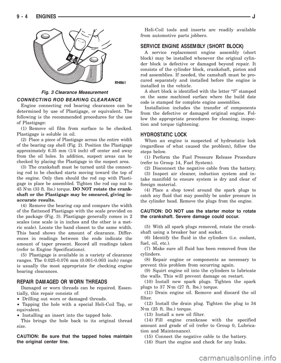
CONNECTING ROD BEARING CLEARANCE
Engine connecting rod bearing clearances can be
determined by use of Plastigage, or equivalent. The
following is the recommended procedures for the use
of Plastigage:
(1) Remove oil film from surface to be checked.
Plastigage is soluble in oil.
(2) Place a piece of Plastigage across the entire width
of the bearing cap shell (Fig. 2). Position the Plastigage
approximately 6.35 mm (1/4 inch) off center and away
from the oil holes. In addition, suspect areas can be
checked by placing the Plastigage in the suspect area.
(3) The crankshaft must be turned until the connect-
ing rod to be checked starts moving toward the top of
the engine. Only then should the rod cap with Plasti-
gage in place be assembled. Tighten the rod cap nut to
45 Nzm (33 ft. lbs.) torque.DO NOT rotate the crank-
shaft or the Plastigage may be smeared, giving in-
accurate results.
(4) Remove the bearing cap and compare the width
of the flattened Plastigage with the scale provided on
the package (Fig. 3). Plastigage generally comes in 2
scales (one scale is in inches and the other is a met-
ric scale). Locate the band closest to the same width.
This band shows the amount of clearance. Differ-
ences in readings between the ends indicate the
amount of taper present. Record all readings taken
(refer to Engine Specifications).
(5) Plastigage is available in a variety of clearance
ranges. The 0.025-0.076 mm (0.001-0.003 inch) range
is usually the most appropriate for checking engine
bearing clearances.
REPAIR DAMAGED OR WORN THREADS
Damaged or worn threads can be repaired. Essen-
tially, this repair consists of:
²Drilling out worn or damaged threads.
²Tapping the hole with a special Heli-Coil Tap, or
equivalent.
²Installing an insert into the tapped hole.
This brings the hole back to its original thread
size.
CAUTION: Be sure that the tapped holes maintain
the original center line.Heli-Coil tools and inserts are readily available
from automotive parts jobbers.
SERVICE ENGINE ASSEMBLY (SHORT BLOCK)
A service replacement engine assembly (short
block) may be installed whenever the original cylin-
der block is defective or damaged beyond repair. It
consists of the cylinder block, crankshaft, piston and
rod assemblies. If needed, the camshaft must be pro-
cured separately and installed before the engine is
installed in the vehicle.
A short block is identified with the letter ``S'' stamped
on the same machined surface where the build date
code is stamped for complete engine assemblies.
Installation includes the transfer of components
from the defective or damaged original engine. Fol-
low the appropriate procedures for cleaning, inspec-
tion and torque tightening.
HYDROSTATIC LOCK
When an engine is suspected of hydrostatic lock
(regardless of what caused the problem), follow the
steps below.
(1) Perform the Fuel Pressure Release Procedure
(refer to Group 14, Fuel System).
(2) Disconnect the negative cable from the battery.
(3) Inspect air cleaner, induction system and in-
take manifold to ensure system is dry and clear of
foreign material.
(4) Place a shop towel around the spark plugs to
catch any fluid that may possibly be under pressure in
the cylinder head. Remove the plugs from the engine.
CAUTION: DO NOT use the starter motor to rotate
the crankshaft. Severe damage could occur.
(5) With all spark plugs removed, rotate the crank-
shaft using a breaker bar and socket.
(6) Identify the fluid in the cylinders (i.e. coolant,
fuel, oil, etc.).
(7) Make sure all fluid has been removed from the
cylinders.
(8) Repair engine or components as necessary to
prevent this problem from occurring again.
(9) Squirt engine oil into the cylinders to lubricate
the walls. This will prevent damage on restart.
(10) Install new spark plugs. Tighten the spark
plugs to 37 Nzm (27 ft. lbs.) torque.
(11) Drain engine oil. Remove and discard the oil
filter.
(12) Install the drain plug. Tighten the plug to 34
Nzm (25 ft. lbs.) torque.
(13) Install a new oil filter.
(14) Fill engine crankcase with the specified
amount and grade of oil (refer to Group 0, Lubrica-
tion and Maintenance).
(15) Connect the negative cable to the battery.
(16) Start the engine and check for any leaks.
Fig. 3 Clearance Measurement
9 - 4 ENGINESJ
Page 1247 of 2198
²The PCM adjusts ignition timing by increasing
and decreasing spark advance.
²The PCM operates the A/C compressor clutch
through the clutch relay. This happens if A/C has
been selected by the vehicle operator and requested
by the A/C thermostat.
The optional Extended Idle Switch is used to raise
the engine idle speed to approximately 1000 rpm.
This is when the shifter is in either the Park or Neu-
tral position. A rocker-type 2-wire switch (extended
idle switch) is mounted to the instrument panel. This
switch will supply a ground circuit to the powertrain
control module (PCM).The switch is available
only with 4.0L engine when supplied with the
optional police package.
CRUISE MODE
When the engine is at operating temperature, this
is a Closed Loop mode. At cruising speed, the power-
train control module (PCM) receives inputs from:
²Air conditioning select signal (if equipped)
²Air conditioning request signal (if equipped)
²Battery voltage
²Engine coolant temperature sensor
²Crankshaft position sensor
²Intake manifold air temperature sensor
²Manifold absolute pressure (MAP) sensor
²Throttle position sensor (TPS)
²Camshaft position sensor signal (in the distribu-
tor)
²Park/neutral switch (gear indicator signalÐauto.
trans. only)
²Oxygen (O2S) sensor
Based on these inputs, the following occurs:
²Voltage is applied to the fuel injectors with the
PCM. The PCM will then adjust the injector pulse
width by turning the ground circuit to each individ-
ual injector on and off.
²The PCM monitors the O2S sensor input and ad-
justs air-fuel ratio. It also adjusts engine idle speed
through the idle air control (IAC) motor.
²The PCM adjusts ignition timing by turning the
ground path to the coil on and off.
²The PCM operates the A/C compressor clutch
through the clutch relay. This happens if A/C has
been selected by the vehicle operator and requested
by the A/C thermostat.
ACCELERATION MODE
This is an Open Loop mode. The powertrain control
module (PCM) recognizes an abrupt increase in
throttle position or MAP pressure as a demand for
increased engine output and vehicle acceleration. The
PCM increases injector pulse width in response to in-
creased throttle opening.
DECELERATION MODE
When the engine is at operating temperature, this
is an Open Loop mode. During hard deceleration, the
powertrain control module (PCM) receives the follow-
ing inputs.
²Air conditioning select signal (if equipped)
²Air conditioning request signal (if equipped)
²Battery voltage
²Engine coolant temperature sensor
²Crankshaft position sensor
²Intake manifold air temperature sensor
²Manifold absolute pressure (MAP) sensor
²Throttle position sensor (TPS)
²Camshaft position sensor signal (in the distribu-
tor)
²Park/neutral switch (gear indicator signalÐauto.
trans. only)
If the vehicle is under hard deceleration with the
proper rpm and closed throttle conditions, the PCM
will ignore the oxygen sensor input signal. The PCM
will enter a fuel cut-off strategy in which it will not
supply battery voltage to the injectors. If a hard de-
celeration does not exist, the PCM will determine the
proper injector pulse width and continue injection.
Based on the above inputs, the PCM will adjust en-
gine idle speed through the idle air control (IAC) mo-
tor.
The PCM adjusts ignition timing by turning the
ground path to the coil on and off.
The PCM opens the ground circuit to the A/C
clutch relay to disengage the A/C compressor clutch.
This is done until the vehicle is no longer under de-
celeration (if the A/C system is operating).
WIDE OPEN THROTTLE MODE
This is an Open Loop mode. During wide open
throttle operation, the powertrain control module
(PCM) receives the following inputs.
²Battery voltage
²Crankshaft position sensor
²Engine coolant temperature sensor
²Intake manifold air temperature sensor
²Manifold absolute pressure (MAP) sensor
²Throttle position sensor (TPS)
²Camshaft position sensor signal (in the distribu-
tor)
During wide open throttle conditions, the following
occurs:
²Voltage is applied to the fuel injectors with the
powertrain control module (PCM). The PCM will
then control the injection sequence and injector pulse
width by turning the ground circuit to each individ-
ual injector on and off. The PCM ignores the oxygen
sensor input signal and provides a predetermined
amount of additional fuel. This is done by adjusting
injector pulse width.
²The PCM adjusts ignition timing by turning the
ground path to the coil on and off.
14 - 32 FUEL SYSTEM COMPONENT DESCRIPTION/SYSTEM OPERATIONJ
Page 1966 of 2198
CLUSTER GROUND; INSTRUMENT
CLUSTER (XJ-RHD)................8W-40-2
CLUSTER ILLUMINATION LAMPS . . 8E-16,8E-26,
8E-34,8E-4
CLUSTER, INSTRUMENT; INSTRUMENT
CLUSTER (XJ).....................8W-40-1
CLUSTER, INSTRUMENT; INSTRUMENT
CLUSTER (XJ-RHD)................8W-40-1
CLUSTER, INSTRUMENT; INSTRUMENT
CLUSTER (YJ).....................8W-40-1
CLUSTER (LHD), HIGH-LINE GAUGE.......8E-9
CLUSTER (LHD), TELL-TALE............8E-10
CLUSTER, LOW-LINE GAUGE............8E-8
CLUSTER, MAIN.....................8E-30
CLUSTERS, INSTRUMENT..........8E-24,8E-1
CLUTCH, A/C COMPRESSOR............24-15
CLUTCH AND BRAKE PACK
REQUIREMENTS, AW-4...............21-341
CLUTCH AND BRAKE PEDAL BUSHINGS . . . 0-22
CLUTCH ASSEMBLY, COMPRESSOR......24-20
CLUTCH COMPONENT LUBRICATION......6-10
CLUTCH COMPONENTS..................6-1
CLUTCH, COMPRESSOR...............24-16
CLUTCH CONTAMINATION...............6-3
CLUTCH COVER AND DISC
INSTALLATION........................6-10
CLUTCH COVER AND DISC REMOVAL.....6-10
CLUTCH COVER AND DISC RUNOUT.......6-3
CLUTCH DIAGNOSIS.....................6-3
CLUTCH DISC AND PLATE THICKNESS,
AW-4 .............................21-338
CLUTCH FLUID LEVEL..................6-14
CLUTCH HOUSING MISALIGNMENT........6-4
CLUTCH HOUSING REPLACEMENT........6-13
CLUTCH HYDRAULIC LINKAGE
INSTALLATION........................6-14
CLUTCH HYDRAULIC LINKAGE REMOVAL . . 6-13
CLUTCH INSPECTION, TORQUE
CONVERTER STATOR................21-199
CLUTCH LINKAGE FLUID.................6-1
CLUTCH MASTER CYLINDER............0-22
CLUTCH MISALIGNMENT................6-3
CLUTCH OPERATION....................6-2
CLUTCH OVERHAUL, DIRECT..........21-228
CLUTCH OVERHAUL, OVERDRIVE
PLANETARY GEAR...................21-218
CLUTCH OVERHAUL, SUN GEAR AND
NO. 1 ONE-WAY....................21-238
CLUTCH PEDAL INSTALLATION..........6-15
CLUTCH PEDAL REMOVAL..............6-15
CLUTCH RELAY, A/C COMPRESSOR . 24-15,24-16
CLUTCH RELAY, AIR CONDITIONING
(A/C)..............................14-58
CLUTCH RELAY TEST, TORQUE
CONVERTER........................14-48
CLUTCH RELAY, TORQUE CONVERTER....14-65
CLUTCH RELAYÐPCM OUTPUT, AIR
CONDITIONING (A/C)..................14-26
CLUTCH RELAYÐPCM OUTPUT, TORQUE
CONVERTER........................14-29
CLUTCH SAFETY PRECAUTIONS..........6-10
CLUTCH SERVICE
.....................6-10
CLUTCH SWITCH, FIN SENSING
CYCLING
......................24-15,24-31
CLUTCH (TCC) SOLENOID AND RELAY,
TORQUE CONVERTER; FUEL/IGNITION
(XJ)
.............................8W-30-4
CLUTCH (TCC) SOLENOID AND RELAY,
TORQUE CONVERTER; TRANSMISSION
CONTROLS (YJ)
...................8W-31-1
CLUTCH (TCC) SOLENOID AND
RELAYÐ2.5L ENGINE ONLY, TORQUE
CONVERTER; TRANSMISSION
CONTROLS (XJ)
...................8W-31-1
CLUTCHÐLOW-REVERSE DRUMÐREAR
SUPPORT OVERHAUL, OVERRUNNING
. . . 21-125
CODE DECODING, VEHICLE
...........Intro.-5
CODE DESIGNATIONS, VEHICLE
........Intro.-1
CODE (DTC), DIAGNOSTIC TROUBLE
.....14-54
CODE, GENERATOR DIAGNOSTIC
TROUBLE
...........................8A-22
CODE IDENTIFICATION, WIRE; WIRING
DIAGRAMSÐGENERAL INFORMATION
(XJ)
...............................8W-1
CODE PLATE, VEHICLE
...............Intro.-4
CODE, SPEED CONTROL DIAGNOSTIC
TROUBLE
...........................8H-5CODES AND DIMENSIONS,
DESIGNATIONS, LABELS/PLATES.......Intro.-1
COIL, EVAPORATOR..................24-30
COIL, IGNITION; FUEL SYSTEM.........14-62
COIL, IGNITION; FUEL/IGNITION (XJ) . . . 8W-30-2
COIL, IGNITION; FUEL/IGNITION (YJ) . . . 8W-30-2
COIL, IGNITION; IGNITION SYSTEMS....8D-22,
8D-4,8D-9
COIL, IGNITION; FUEL/IGNITION
(XJ-RHD).........................8W-30-2
COIL RESISTANCE, IGNITION............8D-9
COIL SPRING........................2-14
COILÐPCM OUTPUT, IGNITION.........14-28
COLD CRANKING SPECIFICATIONS, 2.5L
STARTING SYSTEM...................8A-23
COLD CRANKING SPECIFICATIONS, 4.0L
STARTING SYSTEM...................8A-23
COLUMN ASSEMBLY REPLACEMENT.....19-52
COLUMN COMPONENT SERVICE........19-54
COLUMN GENERAL SERVICEÐXJ,
STEERING..........................19-47
COLUMN, NON-TILT STEERING..........19-60
COLUMN REPLACEMENT..............19-58
COLUMN, TILT STEERING..............19-66
COLUMNÐXJ, STEERING..............19-78
COLUMNÐYJ, STEERING.........19-58,19-78
COMBINATION BUZZER; INTERIOR
LIGHTING (YJ)....................8W-44-1
COMBINATION FLASHER; TURN SIGNALS
(XJ).............................8W-52-1
COMBINATION VALVE..................5-34
COMBINATION VALVE INSTALLATION
(WITH ABS), MASTER CYLINDER.........5-20
COMBINATION VALVE REMOVAL (WITH
ABS), MASTER CYLINDER..............5-17
COMBINATION VALVE REPLACEMENT
(NON-ABS)..........................5-16
COMBUSTION PRESSURE LEAKAGE
TEST, CYLINDER.......................9-6
COMBUSTION PRESSURE LEAKAGE
TEST DIAGNOSIS, CYLINDER.............9-7
COMFORT SWITCH, TRANSMISSION;
TRANSMISSION CONTROLS (XJ-RHD) . . 8W-31-1
COMPASS...........................8C-1
COMPASS/DISPLAY SELF-DIAGNOSTIC
TEST...............................8C-2
COMPASS/THERMOMETER DIAGNOSIS....8C-4
COMPENSATION, CALIPER OPERATION
AND WEAR..........................5-45
COMPONENTSÐYJ, EVAPORATIVE
HOUSING............................24-6
COMPONENTSÐYJ, INSTRUMENT
PANEL............................23-152
COMPONENTSÐYJ VEHICLES, BODY....23-102
COMPRESSION PRESSURE TEST,
CYLINDER............................9-5
COMPRESSOR.......................24-19
COMPRESSOR, A/C; AIR CONDITIONING/
HEATER (YJ)......................8W-42-2
COMPRESSOR, AIR-CONDITIONER........0-21
COMPRESSOR CLUTCH...............24-16
COMPRESSOR CLUTCH, A/C............24-15
COMPRESSOR CLUTCH ASSEMBLY......24-20
COMPRESSOR CLUTCH RELAY, A/C . 24-15,24-16
COMPRESSOR SERVICE...............24-19
CONDENSER, A/C
....................24-34
CONDENSER FILTER DRIERÐ2.5L
ENGINES
...........................24-27
CONDENSERÐ4.0L ENGINES
...........24-28
CONDITION, CHECKING FLUID LEVEL
....21-182
CONDITIONING (A/C) CLUTCH RELAY,
AIR
...............................14-58
CONDITIONING (A/C) CLUTCH
RELAYÐPCM OUTPUT, AIR
............14-26
CONDITIONING (A/C) CONTROLSÐPCM
INPUT, AIR
.........................14-21
CONDITIONING, AIR
..................24-37
CONDITIONING CONTROLSÐXJ
VEHICLES, AIR
......................24-15
CONDITIONING CONTROLSÐYJ
VEHICLES, AIR
......................24-16
CONDITIONING, HEATER AND AIR; AIR
CONDITIONING/HEATER (YJ)
.........8W-42-2
CONDITIONING OPERATION, AIR; AIR
CONDITIONING/HEATER (XJ)
.........8W-42-2
CONDITIONING OPERATION, AIR; AIR
CONDITIONING/HEATER (XJ-RHD)
.....8W-42-2CONDITIONING PERFORMANCE TESTS,
AIR ...............................24-12
CONDITIONING SCHEMATICÐXJ, AIR.....24-5
CONDITIONING TEST PROCEDURES,
HEATING AND AIR....................24-15
CONDITIONS, NORMAL OPERATING........5-3
CONNECTING ROD BEARING FITTING
CHART..........................9-41,9-83
CONNECTING RODS, PISTONS.......9-39,9-81
CONNECTIONS, INTERMITTENT AND
POOR; WIRING DIAGRAMSÐGENERAL
INFORMATION (XJ)...................8W-4
CONNECTIONS, RADIO ILLUMINATION
RELAY..............................8F-4
CONNECTIONS, STARTER RELAY........8A-15
CONNECTOR, ABS DIAGNOSTIC.......5-35,5-3
CONNECTOR AND TERMINAL
REPLACEMENT; WIRING DIAGRAMSÐ
GENERAL INFORMATION (XJ)...........8W-7
CONNECTOR, DATA LINK; ANTI-LOCK
BRAKES (XJ)......................8W-32-2
CONNECTOR, DATA LINK; ANTI-LOCK
BRAKES (XJ-RHD).................8W-32-2
CONNECTOR, DATA LINK; ANTI-LOCK
BRAKES (YJ)......................8W-32-2
CONNECTOR, DATA LINK; FUEL/IGNITION
(XJ).............................8W-30-5
CONNECTOR, DATA LINK; FUEL/IGNITION
(YJ).............................8W-30-5
CONNECTOR, DATA LINK;
TRANSMISSION CONTROLS (XJ-RHD) . . 8W-31-1
CONNECTOR, DATA LINK; FUEL/IGNITION
(XJ-RHD)..........................8W-30-4
CONNECTOR LOCATIONS; CONNECTOR
LOCATIONS (XJ)...................8W-90-1
CONNECTOR LOCATIONS; CONNECTOR
LOCATIONS (XJ-RHD)...............8W-90-1
CONNECTOR LOCATIONS; CONNECTOR
LOCATIONS (YJ)...................8W-90-1
CONNECTOR LOCATIONS; CONNECTOR
PIN OUTS (XJ)....................8W-80-1
CONNECTOR LOCATIONS; CONNECTOR
PIN OUTS (XJ-RHD)................8W-80-1
CONNECTOR LOCATIONS; CONNECTOR
PIN OUTS (YJ)....................8W-80-1
CONNECTOR LOCATIONS; WIRING
DIAGRAMS (XJ)......................8W-1
CONNECTOR LOCATIONS; WIRING
DIAGRAMS (XJ-RHD)..................8W-1
CONNECTOR LOCATIONS; WIRING
DIAGRAMS (YJ)......................8W-1
CONNECTOR, POWERTRAIN CONTROL
MODULE (PCM) 60-WAY...............14-40
CONNECTOR REPLACEMENT; WIRING
DIAGRAMSÐGENERAL INFORMATION
(XJ)...............................8W-6
CONNECTORÐPCM INPUT, DATA LINK . . . 14-22
CONNECTORÐPCM OUTPUT, DATA LINK . . 14-27
CONNECTORS; WIRING DIAGRAMSÐ
GENERAL INFORMATION (XJ)...........8W-2
CONNECTORS (RHD), CLUSTER.........8E-11
CONNECTORS, TERMINAL/CONNECTOR
REPAIRÐMOLEX; WIRING
DIAGRAMSÐGENERAL INFORMATION
(XJ)...............................8W-6
CONSOLE, OVERHEAD; OVERHEAD
CONSOLE (XJ)....................8W-49-1
CONSOLE, OVERHEAD; OVERHEAD
CONSOLE (XJ-RHD)................8W-49-1
CONSOLE REMOVE/INSTALL, OVERHEAD . . . 8C-6
CONSOLE SHIFT, DISASSEMBLYÐ
COLUMN OR........................19-60
CONSOLEÐXJ, FULL FLOOR...........23-95
CONSOLEÐXJ, MINI-FLOOR............23-94
CONSOLEÐXJ, OVERHEAD; BODY
COMPONENTSÐXJ VEHICLES..........23-93
CONSOLEÐXJ, OVERHEAD; LAMPS......8L-17
CONSOLESÐYJ, FLOOR..............23-155
CONTACT PATTERN ANALYSIS,
BACKLASH; FRONT SUSPENSION AND
AXLE...............................2-45
CONTACT PATTERN ANALYSIS,
BACKLASH; REAR SUSPENSION AND
AXLES
..............................3-27
CONTACT/CLOCKSPRING, HORN
.........8G-4
CONTAMINATED BRAKELINING
............5-7
CONTAMINATION, BRAKE FLUID
.......5-10,5-7
CONTAMINATION, CLUTCH
...............6-3
JINDEX 5
Description Group-Page Description Group-Page Description Group-Page
Page 1980 of 2198
MULTI-FUNCTION SWITCH TESTING
PROCEDURESÐXJ....................8L-4
MULTI-PORT FUEL INJECTION
(MFI)ÐCOMPONENT DESCRIPTION/
SYSTEM OPERATION..................14-19
MULTI-PORT FUEL INJECTION
(MFI)ÐCOMPONENT REMOVAL/
INSTALLATION.......................14-58
MULTI-PORT FUEL INJECTION
(MFI)ÐGENERAL DIAGNOSIS...........14-35
NAMEPLATES (ADHESIVE-BACKED)ÐYJ,
EXTERIOR.........................23-120
NAMEPLATESÐXJ, EXTERIOR..........23-26
NEUTRAL SWITCH, PARK..............14-63
NO LUBRICATION, COMPONENTS
REQUIRING...........................0-2
NOISE DIAGNOSIS, 2.5L STARTER.......8A-16
NOISE DIAGNOSIS, STARTER...........8A-16
NOISE, GEAR AND BEARING; FRONT
SUSPENSION AND AXLE................2-18
NOISE, GEAR AND BEARING; REAR
SUSPENSION AND AXLES................3-9
NOISE OR VIBRATION, TIRE.............22-4
NOISE SUPPRESSION, RADIO............8F-2
NOISE/VIBRATION DIAGNOSIS, AXLE;
FRONT SUSPENSION AND AXLE..........2-18
NOISE/VIBRATION DIAGNOSIS, AXLE;
REAR SUSPENSION AND AXLES..........3-9
NO-LEAD FUEL TANK FILLER TUBE......14-13
NON-INTERMITTENT WIPE SWITCH
TESTING...........................8K-14
NON-TILT STEERING COLUMN............19-60
NORMAL BRAKING MODE, ABS
OPERATION IN.......................5-35
NORMAL OPERATING CONDITIONS........5-3
NOTATIONÐSAE AND METRIC, THREAD . Intro.-13
NOTES, CAUTIONS, AND WARNINGS;
WIRING DIAGRAMSÐGENERAL
INFORMATION (XJ)...................8W-1
NOZZLE AND DUCT, DEFROSTER........24-33
NOZZLE REMOVE/INSTALL, LIFTGATE
WASHER...........................8K-24
NOZZLE/TUBEÐXJ, FUEL FILLER........23-26
NP231 SERVICE DIAGNOSIS...........21-285
NP231 TRANSFER CASE........21-283,21-305
NP231 TRANSFER CASE, LEGEND......21-306
NP231/NP242 TORQUE SPECIFICATIONS . 21-344
NP242 SERVICE DIAGNOSIS...........21-308
NP242 TRANSFER CASE........21-307,21-331
NP242 TRANSFER CASE, LEGEND......21-332
NUMBER (VIN) DECODING, VEHICLE
IDENTIFICATION....................Intro.-4
NUMBER (VIN) PLATE, VEHICLE
IDENTIFICATION....................Intro.-4
NUT TIGHTENING, WHEEL..........5-54,5-59
NUT, WHEEL LUG....................22-12
(OHMS)ÐCOOLANT TEMPERATURE
SENSOR/MANIFOLD AIR
TEMPERATURE, SENSOR RESISTANCE
....14-46
OIL CHANGE AND FILTER
REPLACEMENT, ENGINE
................0-16
OIL COOLERS, TRANSMISSION
..........7-36
OIL, ENGINE
.........................0-15
OIL FILTER, ENGINE
...................0-17
OIL FILTER REPLACEMENT
............21-103
OIL PAN
........................9-36,9-77
OIL PRESSURE, ENGINE
.................9-7
OIL PRESSURE GAUGE
..............8W-40-2
OIL PRESSURE WARNING LAMP;
INSTRUMENT CLUSTER (XJ)
.........8W-40-2
OIL PRESSURE WARNING LAMP;
INSTRUMENT CLUSTER (XJ-RHD)
.....8W-40-1
OIL PUMP
.......................9-39,9-81
OIL PUMP OVERHAUL
.........21-131,21-216
OIL PUMP SEAL REPLACEMENT
........21-199
OIL PUMP WEAR LIMITS, AW-4
........21-338
OIL, REFRIGERANT
...................24-12
OIL SEAL REPLACEMENT, INNER AXLE
SHAFT
..............................2-35
OIL SEAL REPLACEMENT, TIMING CASE
COVER
..........................9-30,9-73
OIL SEALS, REAR MAIN
............9-49,9-89
OIL SEALS, VALVE SPRINGS
.............9-23
ON-BOARD DIAGNOSTIC SYSTEM,
USING; BATTERY/STARTING/CHARGING
SYSTEMS DIAGNOSTICS
...............8A-22ON-BOARD DIAGNOSTIC SYSTEM,
USING; VEHICLE SPEED CONTROL
SYSTEM............................8H-5
ON-BOARD DIAGNOSTICS.............8D-15
ON-BOARD DIAGNOSTICS (OBD);
COOLING SYSTEM.....................7-4
ON-BOARD DIAGNOSTICS (OBD); FUEL
SYSTEM............................14-51
ONLY, DAYTIME RUNNING LAMP (DRL)
MODULEÐCANADIAN VEHICLES;
FRONT LIGHTING (YJ)..............8W-50-2
ONLY, POWER STEERING PRESSURE
SWITCHÐ2.5L ENGINE................14-63
ONLY, TORQUE CONVERTER CLUTCH
(TCC) SOLENOID AND RELAYÐ2.5L
ENGINE; TRANSMISSION CONTROLS
(XJ).............................8W-31-1
ONLY, TRANSMISSION CONTROL
MODULEÐ4.0L ENGINE;
TRANSMISSION CONTROLS (XJ)......8W-31-1
OPENING PANEL (GOP)ÐXJ, GRILLE
AND GRILLE.........................23-3
OPENING WEATHERSTRIP SEALÐXJ,
LIFTGATE...........................23-64
OPENING WEATHERSTRIP SEALSÐXJ,
DOOR WINDOW GLASS AND DOOR......23-55
OPERATING SPECIFICATIONS, PUMP......19-3
OPERATION, ACCELERATION SWITCH.....5-37
OPERATION, AIR CONDITIONING; AIR
CONDITIONING/HEATER (XJ).........8W-42-2
OPERATION, AIR CONDITIONING; AIR
CONDITIONING/HEATER (XJ-RHD).....8W-42-2
OPERATION AND APPLICATION CHARTS,
GEARTRAIN........................21-169
OPERATION AND SERVICE, ABS..........5-33
OPERATION AND WEAR
COMPENSATION, CALIPER..............5-45
OPERATION, BRAKE WARNING LIGHT......5-5
OPERATION, CLUTCH...................6-2
OPERATION, COMPONENT
IDENTIFICATION/SYSTEM...............8D-1
OPERATION, ECU.....................5-37
OPERATION, HCU.....................5-36
OPERATION, HEATER AND A/C...........24-1
OPERATION IN ANTILOCK BRAKING
MODE, ABS..........................5-36
OPERATION IN NORMAL BRAKING
MODE, ABS..........................5-35
OPERATION, MULTI-PORT FUEL
INJECTION (MFI)ÐCOMPONENT
DESCRIPTION/SYSTEM................14-19
OPERATION, PARKING BRAKE...........5-60
OPERATION, POWER BRAKE BOOSTER....5-23
OPERATION, POWER STEERING
PUMPÐINITIAL......................19-15
OPERATION, WHEEL SPEED SENSOR......5-37
ORDERÐ2.5L 4-CYLINDER ENGINE,
ENGINE FIRING......................8D-32
ORDERÐ4.0L 6-CYLINDER ENGINE,
ENGINE FIRING......................8D-32
O-RING SEAL, FLOW CONTROL VALVE
FITTING............................19-14
ORNAMENTATION, WHEEL..............22-6
OUTER SCUFF PLATESÐXJ............23-89
OUTLET VACUUM MOTOR
REPLACEMENT, HEATER/DEFROSTER/
INSTRUMENT PANEL..................24-26
OUTPUT, AIR CONDITIONING (A/C)
CLUTCH RELAYÐPCM................14-26
OUTPUT, AUTO SHUTDOWN (ASD)
RELAYÐPCM.......................14-26
OUTPUT, DATA LINK CONNECTORÐPCM . . 14-27
OUTPUT, EMR LAMPÐPCM
............14-27
OUTPUT, FUEL INJECTORSÐPCM
.......14-27
OUTPUT, FUEL PUMP RELAYÐPCM
......14-27
OUTPUT, GENERATOR FIELDÐPCM
......14-27
OUTPUT, GENERATOR LAMPÐPCM
......14-27
OUTPUT, IDLE AIR CONTROL (IAC)
MOTORÐPCM
.......................14-27
OUTPUT, IGNITION COILÐPCM
.........14-28
OUTPUT, MALFUNCTION INDICATOR
LAMPÐPCM
........................14-28
OUTPUT, RADIATOR FAN RELAYÐPCM
. . . 14-28
OUTPUT, SCI TRANSMITÐPCM
.........14-29
OUTPUT, SHIFT INDICATORÐPCM
.......14-29
OUTPUT, SPEED CONTROLÐPCM
.......14-29
OUTPUT, TACHOMETERÐPCM
..........14-29OUTPUT, TORQUE CONVERTER CLUTCH
RELAYÐPCM.......................14-29
OUTPUT VOLTAGE SPECIFICATIONS......8A-23
OUTS, TAKE; WIRING DIAGRAMSÐ
GENERAL INFORMATION (XJ)...........8W-2
OVERDRIVE COMPONENTS, FOURTH
GEAR.............................21-167
OVERDRIVE PLANETARY GEAR AND
CLUTCH OVERHAUL.................21-218
OVERDRIVE SUPPORT OVERHAUL......21-226
OVERHAUL, 30RH/32RH TRANSMISSION . 21-119
OVERHAUL (4-CYLINDER MODELS),
MASTER CYLINDER...................5-16
OVERHAUL, ADAPTER/EXTENSION
HOUSING INSPECTION AND PARK
LOCK COMPONENT..................21-127
OVERHAUL, AW-4 TRANSMISSION......21-201
OVERHAUL, DIFFERENTIAL..............3-46
OVERHAUL, DIRECT CLUTCH..........21-228
OVERHAUL, FIRST-REVERSE BRAKE
PISTON AND TRANSMISSION CASE.....21-247
OVERHAUL, FORWARD CLUTCH........21-232
OVERHAUL, FRONT CLUTCH...........21-134
OVERHAUL, FRONT PLANETARY GEAR . . . 21-237
OVERHAUL, GOVERNOR AND PARK
GEAR.............................21-127
OVERHAUL, MANUAL VALVE SHAFT.....21-215
OVERHAUL, OIL PUMP.........21-131,21-216
OVERHAUL OR FLUID/FILTER CHANGE,
REFILLING AFTER.............21-100,21-182
OVERHAUL, OVERDRIVE PLANETARY
GEAR AND CLUTCH..................21-218
OVERHAUL, OVERDRIVE SUPPORT.....21-226
OVERHAUL, OVERRUNNING CLUTCHÐ
LOW-REVERSE DRUMÐREAR
SUPPORT.........................21-125
OVERHAUL, PLANETARY GEAR TRAIN . . . 21-141
OVERHAUL, REAR CLUTCH............21-138
OVERHAUL, REAR SERVO AND BAND . . . 21-146
OVERHAUL, TRANSFER CASE
DISASSEMBLY................21-289,21-310
OVERHAUL, TRANSMISSION
DISASSEMBLY...................21-37,21-5
OVERHAUL, TRANSMISSION VALVE
BODY.............................21-250
OVERHAUL, WHEEL CYLINDER...........5-57
OVERHEAD CONSOLE; OVERHEAD
CONSOLE (XJ)....................8W-49-1
OVERHEAD CONSOLE; OVERHEAD
CONSOLE (XJ-RHD)................8W-49-1
OVERHEAD CONSOLE REMOVE/INSTALL . . . 8C-6
OVERHEAD CONSOLEÐXJ; BODY
COMPONENTSÐXJ VEHICLES..........23-93
OVERHEAD CONSOLEÐXJ; LAMPS......8L-17
OXYGEN (O2S) SENSOR; EMISSION
CONTROL SYSTEMS...............25-6,25-7
OXYGEN (O2S) SENSOR; FUEL SYSTEM . . 14-63
OXYGEN (O2S) SENSOR; IGNITION
SYSTEMS......................8D-23,8D-5
OXYGEN (O2S) SENSOR TESTS.........8D-15
OXYGEN (O2S) SENSORÐPCM INPUT....14-24
OXYGEN SENSOR, HEATED; FUEL/
IGNITION (XJ).....................8W-30-3
OXYGEN SENSOR, HEATED; FUEL/
IGNITION (YJ).....................8W-30-3
OXYGEN SENSOR, HEATED; FUEL/
IGNITION (XJ-RHD)................8W-30-3
OXYGEN SENSOR (O2S) HEATING
ELEMENT TEST
......................14-48
PACK MEASUREMENT AND
ADJUSTMENT, DIFFERENTIAL SHIM
.......2-43
PACK REQUIREMENTS, AW-4 CLUTCH
AND BRAKE
........................21-341
PACKAGE CLUSTER, GAUGE
.......8E-31,8E-43
PAINT
............................23-158
PAINT AND TRIM REPAIR PRODUCTSÐ
XJ, AFTERMARKET
..................23-159
PAINT AND TRIM REPAIR PRODUCTSÐ
YJ, AFTERMARKET
..................23-160
PAINTED SURFACE TOUCH-UP
.........23-158
PAN, OIL
........................9-36,9-77
PANEL AND GAUGESÐYJ, INSTRUMENT
. . 8E-24
PANEL COMPONENTSÐYJ,
INSTRUMENT
......................23-152
PANEL DIMMER SWITCH REMOVE/
INSTALL, HEADLAMP OR
..............8E-42
PANEL EXTENSIONÐXJ, QUARTER TRIM
. 23-87
JINDEX 19
Description Group-Page Description Group-Page Description Group-Page