1995 JEEP CHEROKEE Transmission adjustment
[x] Cancel search: Transmission adjustmentPage 1477 of 2198
(c) Vehicle is used for trailer towing or heavy
load hauling.
FLUID/FILTER REPLACEMENT PROCEDURE
(1) Raise vehicle.
(2) Remove oil pan and drain fluid.
(3) Clean oil pan and pan magnet. Then clean re-
maining gasket material from gasket surface of
transmission case.
(4) Remove fluid filter screws and remove filter.
(5) Position new filter on valve body and install fil-
ter screws. Tighten screws to 4 Nzm (35 in. lbs.)
torque.
(6) Adjust rear band at this time if required.
(7) Position new gasket on oil pan and install pan
on transmission. Tighten pan bolts to 150 in. lbs. (17
Nzm) torque.
(8) Adjust front band at this time if required.
(9) Lower vehicle and refill transmission with Mo-
par ATF Plus, type 7176 fluid.
REFILLING AFTER OVERHAUL OR FLUID/FILTER
CHANGE
The most effective way to avoid overfilling after a
fluid change or overhaul is as follows:
(1) Remove dipstick and insert clean funnel in
transmission fill tube.
(2) Add following initial quantity of Mopar ATF
Plus to transmission:
(a) If only fluid and filter were changed, add3
pints (1-1/2 quarts)of ATF Plus to transmission.
(b) If transmission was completely overhauled
and torque converter was replaced or drained, add
10 pints (5 quarts)of ATF Plus to transmission.
(3) Apply parking brakes.
(4) Start and run engine at normal curb idle speed.
(5) Apply service brakes, shift transmission
through all gear ranges then back to Neutral, and
leave engine running at curb idle speed.
(6) Remove funnel, insert dipstick and check fluid
level. Add only enough fluid to bring level toMIN
dot mark on dipstick.
(7) Drive vehicle until transmission fluid is at nor-
mal operating temperature. Then recheck fluid level
as described in next step.
(8) Leave engine running at curb idle speed, shift
into Neutral, and check fluid level again. This time,
add just enough fluid to bring level up toMAX ar-
row mark but do not overfill.
(9) When fluid level is correct, shut engine off, re-
lease park brake, remove funnel, and reseat dipstick
in fill tube.
SHIFT LINKAGE ADJUSTMENT (YJ)
(1) Check linkage adjustment by starting engine in
Park and Neutral.(2) Adjustment is OK if engine starts only in park
and Neutral. Adjustment is incorrect if engine starts
in one but not both positions.
(3) If engine starts in any position other than Park
or Neutral, or if engine will not start at all, park/
neutral position switch may be faulty.
(4) Shift transmission into Park.
(5) Raise vehicle.
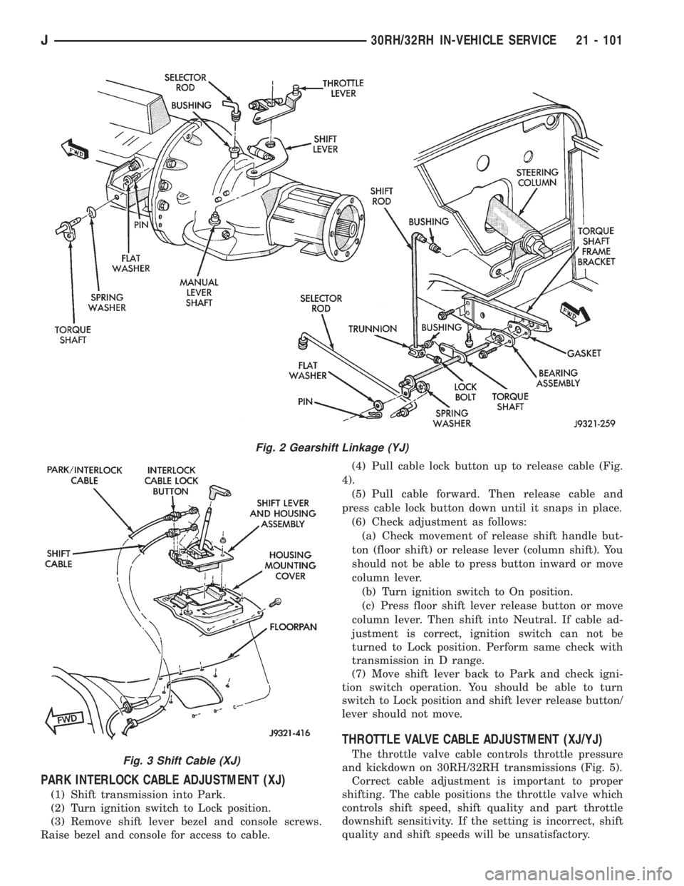
(6) Check condition of shift rods, bellcrank,
bellcrank brackets and linkage bushings/grommets
(Fig. 2). Tighten, repair, replace worn, damaged
parts. Do not attempt adjustment if linkage compo-
nents are worn or damaged.
(7) Loosen shift rod trunnion lock bolt or nut. Be
sure upper shift rod slides freely in trunnion (Fig. 2).
Also be sure shift rods and bellcrank rotate freely
and do not bind at any point.
(8) Verify that manual lever is in Park detent (Fig.
2). Move lever all the way rearward to be sure it is in
Park.
(9) Check for positive engagement of park lock by
attempting to rotate propeller shaft. Shaft will not
turn when park pawl is engaged.
(10) Adjust shift rod trunnion to a obtain free pin
fit in bellcrank arm and tighten trunnion lock bolt or
nut. Prevent shift rod from turning while tightening
bolt or nut. Gearshift linkage lash must be elimi-
nated to obtain proper adjustment. Eliminate lash by
pulling downward on shift rod and pressing upward
on bellcrank.
(11) Confirm proper adjustment by starting engine
in Park and Neutral. Engine should start in these
positions only.If engine starts in any position
other than Park or Neutral, adjustment is in-
correct or neutral switch is faulty.
(12) Lower vehicle and verify that steering lock op-
erates correctly.
SHIFT CABLE ADJUSTMENT (XJ)
(1) Shift transmission into Park.
(2) Raise vehicle.
(3) Release cable adjuster clamp to unlock cable
(Figs. 3 and 4). Clamp is at transmission end of ca-
ble.
(4) Unsnap cable from transmission cable bracket.
(5) Move transmission shift lever fully rearward to
Park detent. Lever is on manual valve shaft at driver
side of case.
(6) Verify positive engagement of park lock by at-
tempting to rotate propeller shaft. Shaft will not ro-
tate when park lock is engaged.
(7) Snap cable into cable bracket.
(8) Lock shift cable by pressing cable adjuster
clamp down until it snaps into place.
(9) Check engine starting. Engine should start only
in Park and Neutral.
(10) Lower vehicle.
21 - 100 30RH/32RH IN-VEHICLE SERVICEJ
Page 1478 of 2198
PARK INTERLOCK CABLE ADJUSTMENT (XJ)
(1) Shift transmission into Park.
(2) Turn ignition switch to Lock position.
(3) Remove shift lever bezel and console screws.
Raise bezel and console for access to cable.(4) Pull cable lock button up to release cable (Fig.
4).
(5) Pull cable forward. Then release cable and
press cable lock button down until it snaps in place.
(6) Check adjustment as follows:
(a) Check movement of release shift handle but-
ton (floor shift) or release lever (column shift). You
should not be able to press button inward or move
column lever.
(b) Turn ignition switch to On position.
(c) Press floor shift lever release button or move
column lever. Then shift into Neutral. If cable ad-
justment is correct, ignition switch can not be
turned to Lock position. Perform same check with
transmission in D range.
(7) Move shift lever back to Park and check igni-
tion switch operation. You should be able to turn
switch to Lock position and shift lever release button/
lever should not move.
THROTTLE VALVE CABLE ADJUSTMENT (XJ/YJ)
The throttle valve cable controls throttle pressure
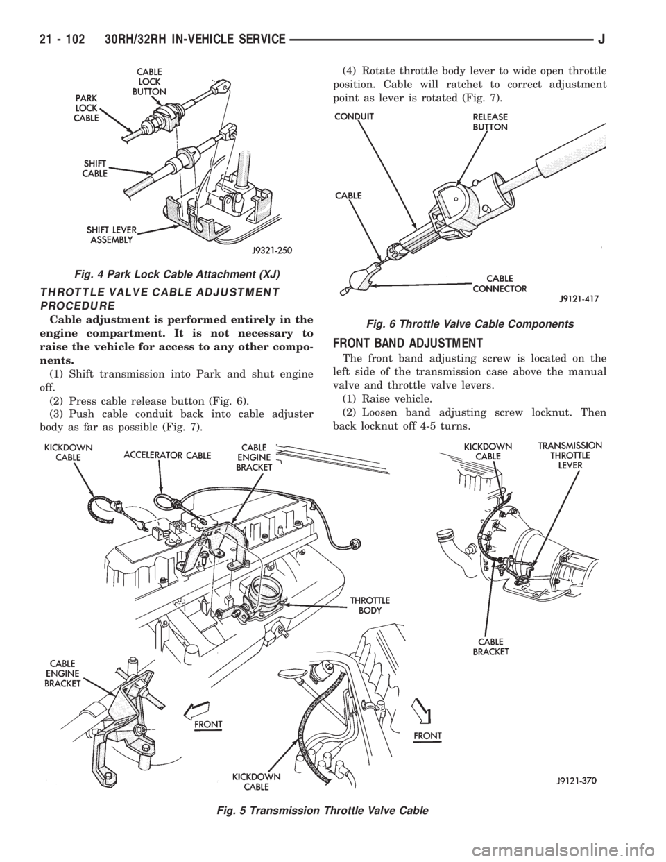
and kickdown on 30RH/32RH transmissions (Fig. 5).
Correct cable adjustment is important to proper
shifting. The cable positions the throttle valve which
controls shift speed, shift quality and part throttle
downshift sensitivity. If the setting is incorrect, shift
quality and shift speeds will be unsatisfactory.
Fig. 2 Gearshift Linkage (YJ)
Fig. 3 Shift Cable (XJ)
J30RH/32RH IN-VEHICLE SERVICE 21 - 101
Page 1479 of 2198
THROTTLE VALVE CABLE ADJUSTMENT
PROCEDURE
Cable adjustment is performed entirely in the
engine compartment. It is not necessary to
raise the vehicle for access to any other compo-
nents.
(1) Shift transmission into Park and shut engine
off.
(2) Press cable release button (Fig. 6).
(3) Push cable conduit back into cable adjuster
body as far as possible (Fig. 7).(4) Rotate throttle body lever to wide open throttle
position. Cable will ratchet to correct adjustment
point as lever is rotated (Fig. 7).
FRONT BAND ADJUSTMENT
The front band adjusting screw is located on the
left side of the transmission case above the manual
valve and throttle valve levers.
(1) Raise vehicle.
(2) Loosen band adjusting screw locknut. Then
back locknut off 4-5 turns.
Fig. 5 Transmission Throttle Valve Cable
Fig. 4 Park Lock Cable Attachment (XJ)
Fig. 6 Throttle Valve Cable Components
21 - 102 30RH/32RH IN-VEHICLE SERVICEJ
Page 1480 of 2198
(3) Clean adjusting screw threads with Mopar rust
penetrant if necessary. Then lubricate threads with
Mopar spray lube or petroleum jelly. Be sure screw
turns freely in case. This is necessary for accurate
adjustment.
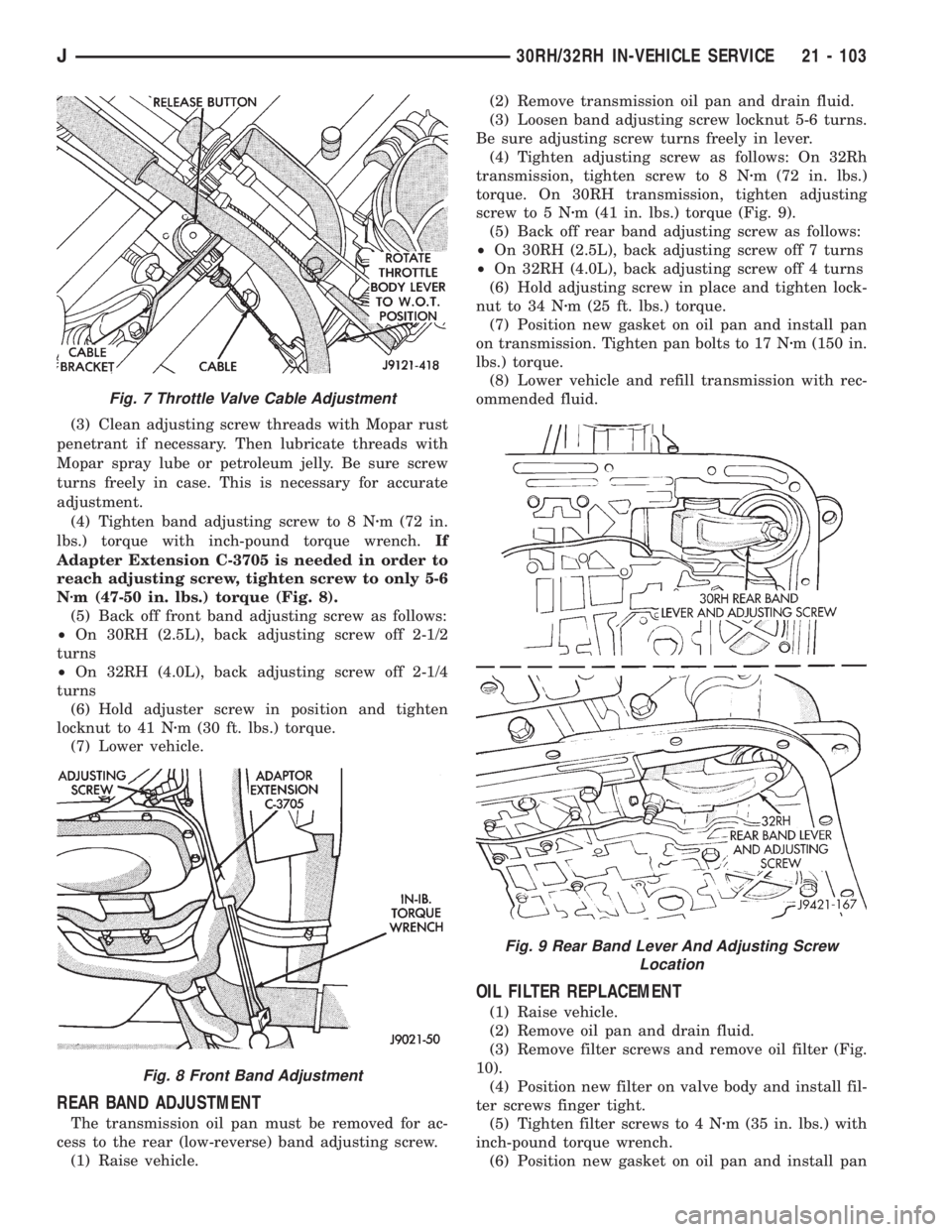
(4) Tighten band adjusting screw to 8 Nzm (72 in.
lbs.) torque with inch-pound torque wrench.If
Adapter Extension C-3705 is needed in order to
reach adjusting screw, tighten screw to only 5-6
Nzm (47-50 in. lbs.) torque (Fig. 8).
(5) Back off front band adjusting screw as follows:
²On 30RH (2.5L), back adjusting screw off 2-1/2
turns
²On 32RH (4.0L), back adjusting screw off 2-1/4
turns
(6) Hold adjuster screw in position and tighten
locknut to 41 Nzm (30 ft. lbs.) torque.
(7) Lower vehicle.
REAR BAND ADJUSTMENT
The transmission oil pan must be removed for ac-
cess to the rear (low-reverse) band adjusting screw.
(1) Raise vehicle.(2) Remove transmission oil pan and drain fluid.
(3) Loosen band adjusting screw locknut 5-6 turns.
Be sure adjusting screw turns freely in lever.
(4) Tighten adjusting screw as follows: On 32Rh
transmission, tighten screw to 8 Nzm (72 in. lbs.)
torque. On 30RH transmission, tighten adjusting
screw to 5 Nzm (41 in. lbs.) torque (Fig. 9).
(5) Back off rear band adjusting screw as follows:
²On 30RH (2.5L), back adjusting screw off 7 turns
²On 32RH (4.0L), back adjusting screw off 4 turns
(6) Hold adjusting screw in place and tighten lock-
nut to 34 Nzm (25 ft. lbs.) torque.
(7) Position new gasket on oil pan and install pan
on transmission. Tighten pan bolts to 17 Nzm (150 in.
lbs.) torque.
(8) Lower vehicle and refill transmission with rec-
ommended fluid.
OIL FILTER REPLACEMENT
(1) Raise vehicle.
(2) Remove oil pan and drain fluid.
(3) Remove filter screws and remove oil filter (Fig.
10).
(4) Position new filter on valve body and install fil-
ter screws finger tight.
(5) Tighten filter screws to 4 Nzm (35 in. lbs.) with
inch-pound torque wrench.
(6) Position new gasket on oil pan and install pan
Fig. 7 Throttle Valve Cable Adjustment
Fig. 8 Front Band Adjustment
Fig. 9 Rear Band Lever And Adjusting Screw
Location
J30RH/32RH IN-VEHICLE SERVICE 21 - 103
Page 1496 of 2198
30RH/32RH TRANSMISSION OVERHAUL
INDEX
page page
Adapter/Extension Housing Inspection and Park
Lock Component Overhaul................ 127
Front Clutch Overhaul..................... 134
Front Servo and Band Overhaul............. 146
Governor and Park Gear Overhaul........... 127
Oil Pump Overhaul....................... 131
Overhaul Service Information................ 125
Overrunning ClutchÐLow-Reverse DrumÐRear
Support Overhaul....................... 125
Planetary Gear Train Overhaul.............. 141Rear Clutch Overhaul..................... 138
Rear Servo and Band Overhaul.............. 146
Transmission Assembly and Adjustment Procedures. 155
Transmission Assembly Tips................ 155
Transmission Case Cleaning and Inspection.... 125
Transmission Disassembly.................. 119
Valve Body Assembly and Adjustment......... 153
Valve Body Disassembly and Inspection....... 147
TRANSMISSION DISASSEMBLY
(1) Clean transmission exterior with steam gun or
with solvent. Wear eye protection during cleaning
process.
(2) Remove throttle and shift levers from valve
body manual shaft and throttle lever shaft.
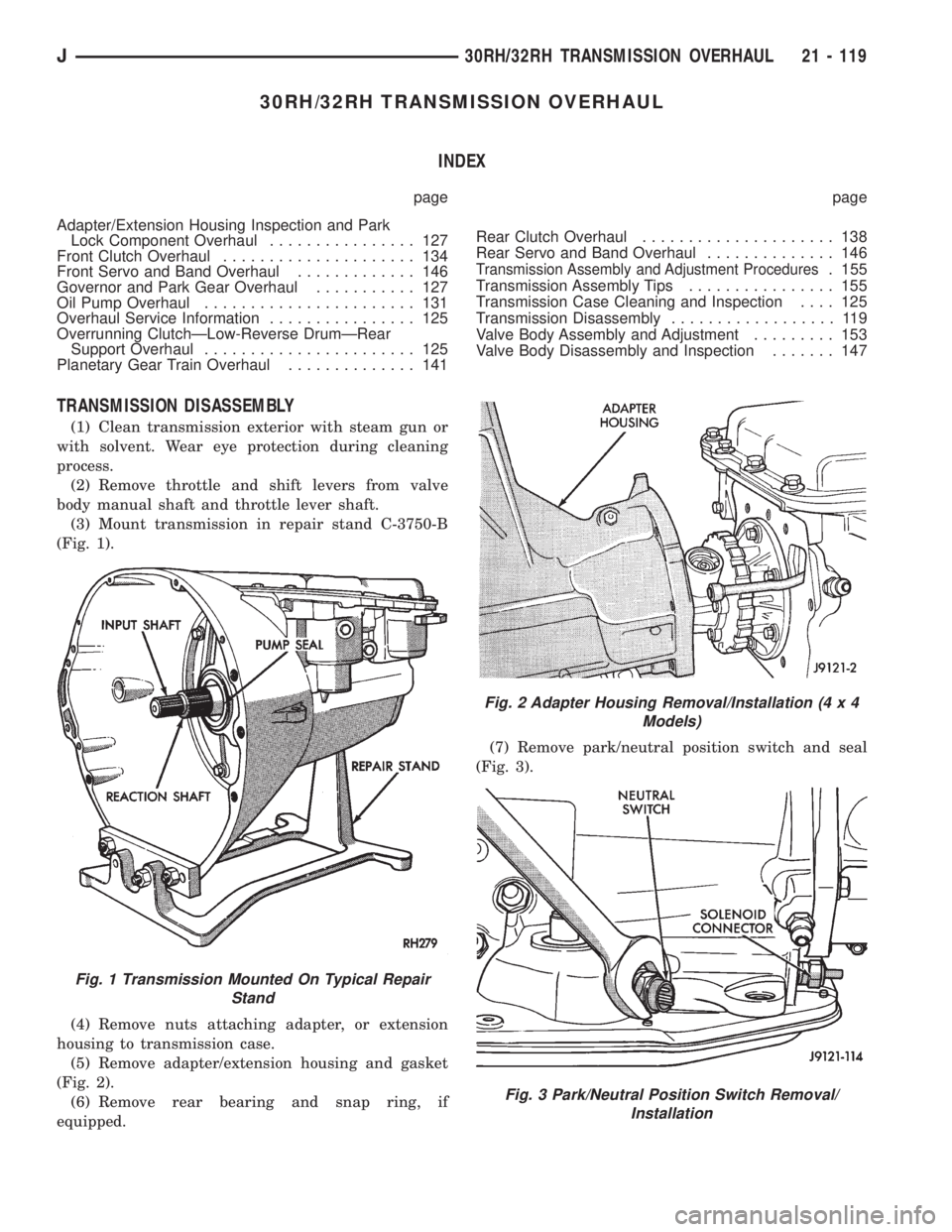
(3) Mount transmission in repair stand C-3750-B
(Fig. 1).
(4) Remove nuts attaching adapter, or extension
housing to transmission case.
(5) Remove adapter/extension housing and gasket
(Fig. 2).
(6) Remove rear bearing and snap ring, if
equipped.(7) Remove park/neutral position switch and seal
(Fig. 3).
Fig. 1 Transmission Mounted On Typical Repair
Stand
Fig. 2 Adapter Housing Removal/Installation (4 x 4
Models)
Fig. 3 Park/Neutral Position Switch Removal/
Installation
J30RH/32RH TRANSMISSION OVERHAUL 21 - 119
Page 1507 of 2198
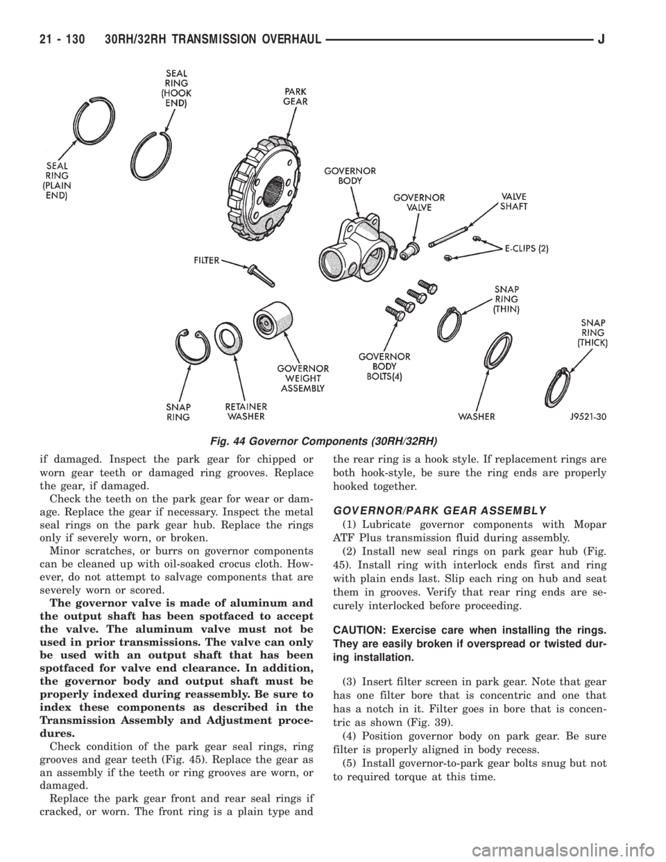
if damaged. Inspect the park gear for chipped or
worn gear teeth or damaged ring grooves. Replace
the gear, if damaged.
Check the teeth on the park gear for wear or dam-
age. Replace the gear if necessary. Inspect the metal
seal rings on the park gear hub. Replace the rings
only if severely worn, or broken.
Minor scratches, or burrs on governor components
can be cleaned up with oil-soaked crocus cloth. How-
ever, do not attempt to salvage components that are
severely worn or scored.
The governor valve is made of aluminum and
the output shaft has been spotfaced to accept
the valve. The aluminum valve must not be
used in prior transmissions. The valve can only
be used with an output shaft that has been
spotfaced for valve end clearance. In addition,
the governor body and output shaft must be
properly indexed during reassembly. Be sure to
index these components as described in the
Transmission Assembly and Adjustment proce-
dures.
Check condition of the park gear seal rings, ring
grooves and gear teeth (Fig. 45). Replace the gear as
an assembly if the teeth or ring grooves are worn, or
damaged.
Replace the park gear front and rear seal rings if
cracked, or worn. The front ring is a plain type andthe rear ring is a hook style. If replacement rings are
both hook-style, be sure the ring ends are properly
hooked together.
GOVERNOR/PARK GEAR ASSEMBLY
(1) Lubricate governor components with Mopar
ATF Plus transmission fluid during assembly.
(2) Install new seal rings on park gear hub (Fig.
45). Install ring with interlock ends first and ring
with plain ends last. Slip each ring on hub and seat
them in grooves. Verify that rear ring ends are se-
curely interlocked before proceeding.
CAUTION: Exercise care when installing the rings.
They are easily broken if overspread or twisted dur-
ing installation.
(3) Insert filter screen in park gear. Note that gear
has one filter bore that is concentric and one that
has a notch in it. Filter goes in bore that is concen-
tric as shown (Fig. 39).
(4) Position governor body on park gear. Be sure
filter is properly aligned in body recess.
(5) Install governor-to-park gear bolts snug but not
to required torque at this time.
Fig. 44 Governor Components (30RH/32RH)
21 - 130 30RH/32RH TRANSMISSION OVERHAULJ
Page 1530 of 2198
VALVE BODY ASSEMBLY AND ADJUSTMENT
CAUTION: Do not force valves or plugs into place
during reassembly. If the valve body bores, valves
and plugs are free of distortion or burrs, the valve
body components should all slide into place easily.
In addition, do not overtighten the transfer plate
and valve body screws during reassembly. Over-
tightening can distort the valve body resulting in
valve sticking, cross leakage and unsatisfactory op-
eration. Tighten valve body screws to recom-
mended torque only.
(1) Lubricate valve body bores, valves and plugs
with Mopar ATF Plus transmission fluid.
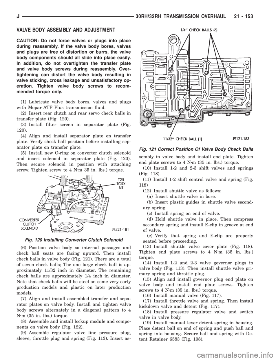
(2) Insert rear clutch and rear servo check balls in
transfer plate (Fig. 120).
(3) Install filter screen in separator plate (Fig.
120).
(4) Align and install separator plate on transfer
plate. Verify check ball position before installing sep-
arator plate on transfer plate.
(5) Install new O-ring on converter clutch solenoid
and insert solenoid in separator plate (Fig. 120).
Then secure solenoid in position with attaching
screw. Tighten screw to 4 Nzm 35 in. lbs.) torque.
(6) Position valve body so internal passages and
check ball seats are facing upward. Then install
check balls in valve body (Fig. 121). There are a total
of seven check balls; The one large check ball is ap-
proximately 11/32 inch in diameter. The remaining
check balls are approximately 1/4 inch in diameter.
Note that check balls will be steel on some very early
production models and plastic on later production
models.
(7) Align and install assembled transfer and sepa-
rator plates on valve body. Install and tighten valve
body screws alternately in a diagonal pattern to 4
Nzm (35 in. lbs.) torque.
(8) Assemble and install lockup module and compo-
nents on valve body (Fig. 122).
(9) Assemble regulator valve line pressure plug,
sleeve, throttle plug and spring (Fig. 113). Insert as-sembly in valve body and install end plate. Tighten
end plate screws to 4 Nzm (35 in. lbs.) torque.
(10) Install 1-2 and 2-3 shift valves and springs
(Fig. 118).
(11) Install 1-2 shift control valve and spring (Fig.
118)
(12) Install shuttle valve as follows:
(a) Insert shuttle valve in bore.
(b) Insert plastic guides in shuttle valve second-
ary spring.
(c) Install spring on end of valve.
(d) Hold shuttle valve in place. Then compress
secondary spring and install E-clip in groove at end
of valve.
(e) Verify that spring and E-clip are properly
seated before proceeding.
(13) Install shuttle valve cover plate (Fig. 118).
Tighten end plate screws to 4 Nzm (35 in. lbs.)
torque.
(14) Install 1-2 and 2-3 valve governor plugs in
valve body (Fig. 113). Then install shuttle valve pri-
mary spring and throttle plug.
(15) Align and install governor plug end plate on
valve body and install end plate screws. Tighten
screws to 4 Nzm (35 in. lbs.) torque.
(16) Install manual valve (Fig. 117).
(17) Install throttle valve and spring. Then install
kickdown valve and detent (Fig. 117).
(18) Install pressure regulator valve and switch
valve in valve body.
(19) Install manual lever detent spring in housing.
Place detent ball on end of spring and push ball and
spring into housing. Secure ball and spring with De-
tent Retainer 6583 (Fig. 108).
Fig. 120 Installing Converter Clutch Solenoid
Fig. 121 Correct Position Of Valve Body Check Balls
J30RH/32RH TRANSMISSION OVERHAUL 21 - 153
Page 1531 of 2198
(20) Insert line pressure adjusting screw in adjust-
ing screw bracket (Fig. 107).
(21) Install spring on end of line pressure regula-
tor valve.
(22) Install switch valve spring on tang at end of
adjusting screw bracket (Fig. 107).
(23) Position adjusting screw bracket on valve
body. Align valve springs and press bracket into
place. Install short, upper bracket screws first and
long bottom screw last. Verify that valve springs and
bracket are properly aligned. Then tighten all three
bracket screws to 4 Nzm (35 in. lbs.) torque.
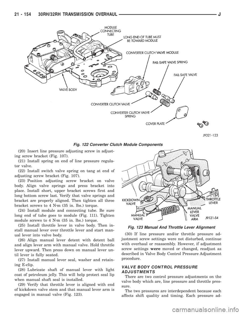
(24) Install module and connecting tube. Be sure
long end of tube goes to module (Fig. 111). Tighten
module screws to 4 Nzm (35 in. lbs.) torque.
(25) Install throttle lever in valve body. Then in-
stall manual lever over throttle lever and start man-
ual lever into valve body.
(26) Align manual lever detent with detent ball
and align lever arm with manual valve. Hold throttle
lever upward. Then press down on manual lever un-
til lever is fully seated.
(27) Install manual lever seal, washer and retain-
ing E-clip.
(28) Lubricate shaft of manual lever with light
coat of petroleum jelly. This will help protect seal lip
when manual shaft seal is installed.
(29) Verify that throttle lever is aligned with end
of kickdown valve stem and that manual lever arm is
engaged in manual valve (Fig. 123).(30) If line pressure and/or throttle pressure ad-
justment screw settings were not disturbed, continue
with overhaul or reassembly. However, if adjustment
screw settingsweremoved or changed, readjust as
described in Valve Body Control Pressure Adjustment
procedure.
VALVE BODY CONTROL PRESSURE
ADJUSTMENTS
There are two control pressure adjustments on the
valve body which are, line pressure and throttle pres-
sure.
The two pressures are interdependent because each
affects shift quality and timing. Each pressure ad-
Fig. 122 Converter Clutch Module Components
Fig. 123 Manual And Throttle Lever Alignment
21 - 154 30RH/32RH TRANSMISSION OVERHAULJ