1995 JEEP CHEROKEE Transmission adjustment
[x] Cancel search: Transmission adjustmentPage 1570 of 2198
(4) Install new O-ring on speed sensor and install
sensor in transmission case.
(5) Install sensor bracket and retainer bolt.
Tighten bolt to 7.4 Nzm (65 in. lbs.) torque.
(6) Connect sensor wire harness connector.
SPEED SENSOR ROTORÐSPEEDOMETER DRIVE
GEAR
ROTORÐDRIVE GEAR REMOVAL
(1) Raise vehicle.
(2) Remove components necessary to gain access to
rotor and drive gear such as propeller shaft, transfer
case, crossmember, and shift linkage.
(3) Disconnect speedometer cable and/or speed sen-
sor.
(4) Remove adaptor housing.
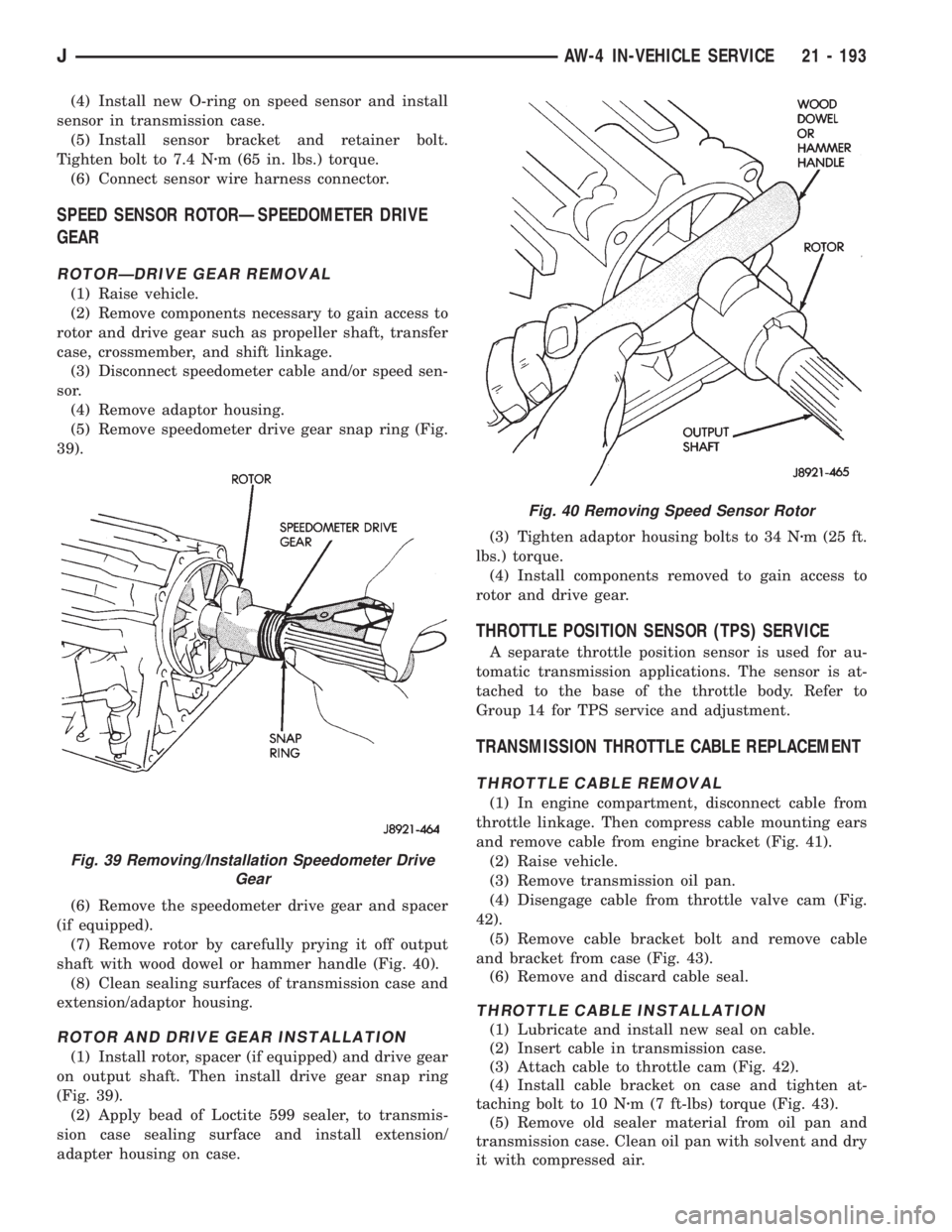
(5) Remove speedometer drive gear snap ring (Fig.
39).
(6) Remove the speedometer drive gear and spacer
(if equipped).
(7) Remove rotor by carefully prying it off output
shaft with wood dowel or hammer handle (Fig. 40).
(8) Clean sealing surfaces of transmission case and
extension/adaptor housing.
ROTOR AND DRIVE GEAR INSTALLATION
(1) Install rotor, spacer (if equipped) and drive gear
on output shaft. Then install drive gear snap ring
(Fig. 39).
(2) Apply bead of Loctite 599 sealer, to transmis-
sion case sealing surface and install extension/
adapter housing on case.(3) Tighten adaptor housing bolts to 34 Nzm (25 ft.
lbs.) torque.
(4) Install components removed to gain access to
rotor and drive gear.
THROTTLE POSITION SENSOR (TPS) SERVICE
A separate throttle position sensor is used for au-
tomatic transmission applications. The sensor is at-
tached to the base of the throttle body. Refer to
Group 14 for TPS service and adjustment.
TRANSMISSION THROTTLE CABLE REPLACEMENT
THROTTLE CABLE REMOVAL
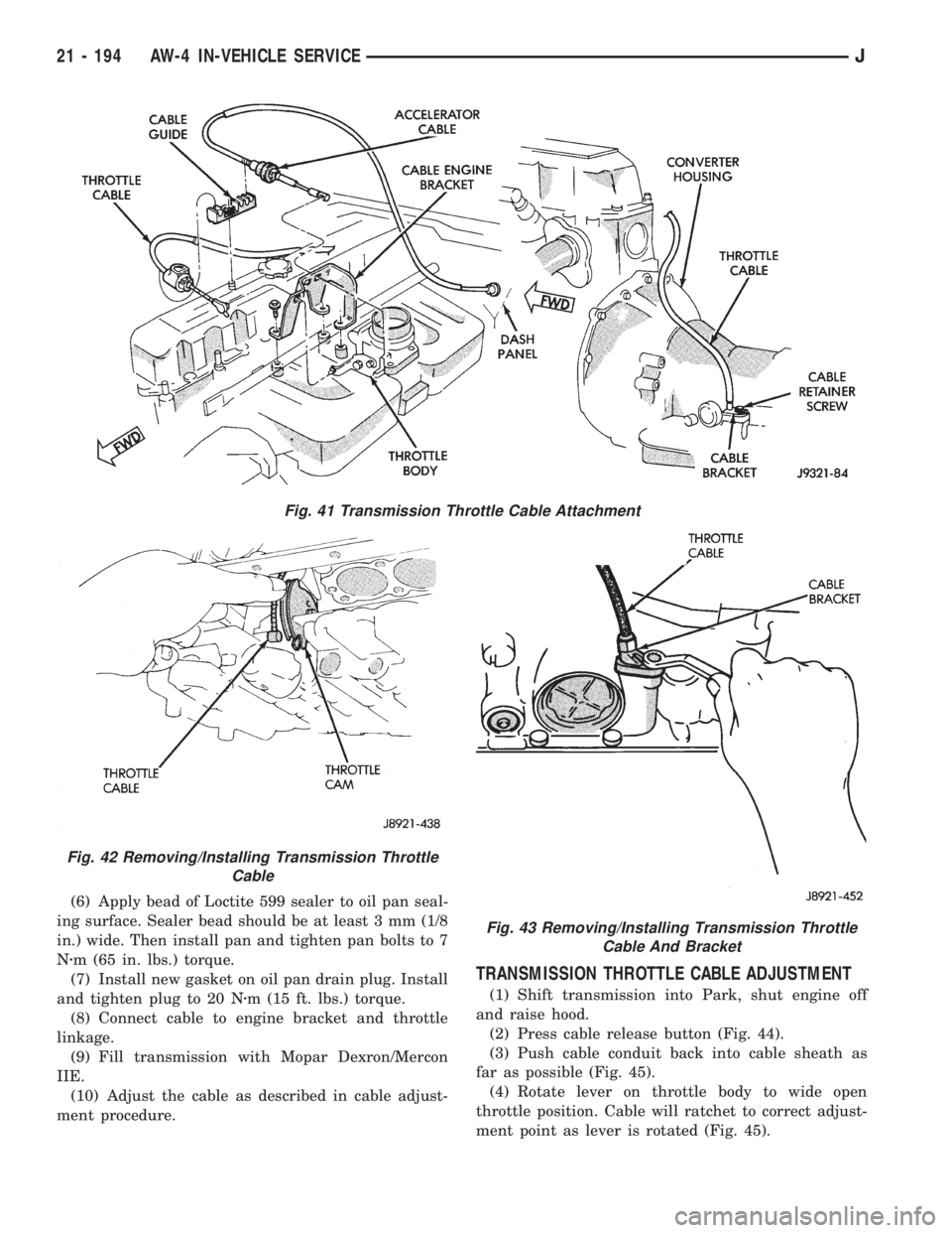
(1) In engine compartment, disconnect cable from
throttle linkage. Then compress cable mounting ears
and remove cable from engine bracket (Fig. 41).
(2) Raise vehicle.
(3) Remove transmission oil pan.
(4) Disengage cable from throttle valve cam (Fig.
42).
(5) Remove cable bracket bolt and remove cable
and bracket from case (Fig. 43).
(6) Remove and discard cable seal.
THROTTLE CABLE INSTALLATION
(1) Lubricate and install new seal on cable.
(2) Insert cable in transmission case.
(3) Attach cable to throttle cam (Fig. 42).
(4) Install cable bracket on case and tighten at-
taching bolt to 10 Nzm (7 ft-lbs) torque (Fig. 43).
(5) Remove old sealer material from oil pan and
transmission case. Clean oil pan with solvent and dry
it with compressed air.
Fig. 40 Removing Speed Sensor Rotor
Fig. 39 Removing/Installation Speedometer Drive
Gear
JAW-4 IN-VEHICLE SERVICE 21 - 193
Page 1571 of 2198
(6) Apply bead of Loctite 599 sealer to oil pan seal-
ing surface. Sealer bead should be at least 3 mm (1/8
in.) wide. Then install pan and tighten pan bolts to 7
Nzm (65 in. lbs.) torque.
(7) Install new gasket on oil pan drain plug. Install
and tighten plug to 20 Nzm (15 ft. lbs.) torque.
(8) Connect cable to engine bracket and throttle
linkage.
(9) Fill transmission with Mopar Dexron/Mercon
IIE.
(10) Adjust the cable as described in cable adjust-
ment procedure.
TRANSMISSION THROTTLE CABLE ADJUSTMENT
(1) Shift transmission into Park, shut engine off
and raise hood.
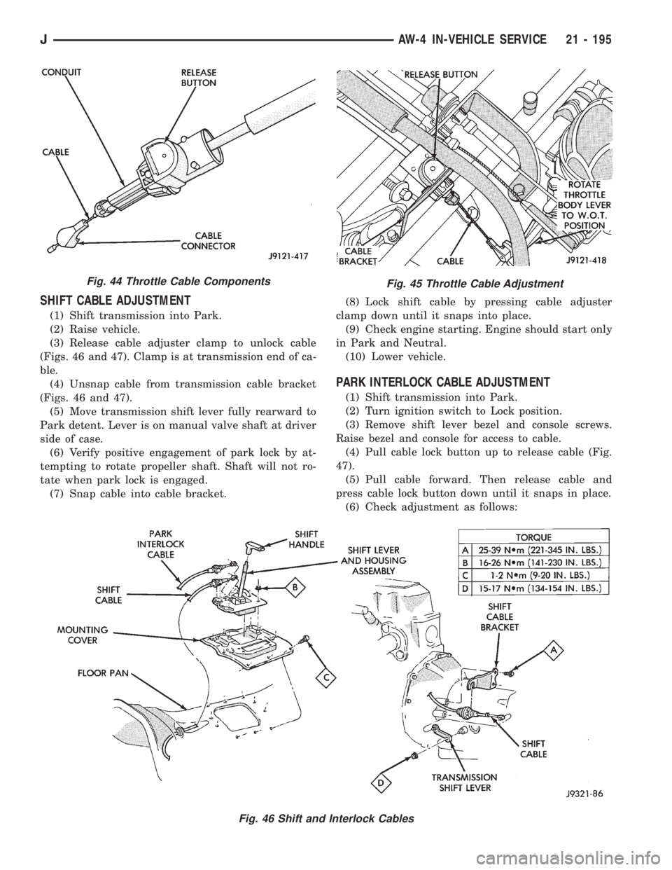
(2) Press cable release button (Fig. 44).
(3) Push cable conduit back into cable sheath as
far as possible (Fig. 45).
(4) Rotate lever on throttle body to wide open
throttle position. Cable will ratchet to correct adjust-
ment point as lever is rotated (Fig. 45).
Fig. 43 Removing/Installing Transmission Throttle
Cable And Bracket
Fig. 41 Transmission Throttle Cable Attachment
Fig. 42 Removing/Installing Transmission Throttle
Cable
21 - 194 AW-4 IN-VEHICLE SERVICEJ
Page 1572 of 2198
SHIFT CABLE ADJUSTMENT
(1) Shift transmission into Park.
(2) Raise vehicle.
(3) Release cable adjuster clamp to unlock cable
(Figs. 46 and 47). Clamp is at transmission end of ca-
ble.
(4) Unsnap cable from transmission cable bracket
(Figs. 46 and 47).
(5) Move transmission shift lever fully rearward to
Park detent. Lever is on manual valve shaft at driver
side of case.
(6) Verify positive engagement of park lock by at-
tempting to rotate propeller shaft. Shaft will not ro-
tate when park lock is engaged.
(7) Snap cable into cable bracket.(8) Lock shift cable by pressing cable adjuster
clamp down until it snaps into place.
(9) Check engine starting. Engine should start only
in Park and Neutral.
(10) Lower vehicle.
PARK INTERLOCK CABLE ADJUSTMENT
(1) Shift transmission into Park.
(2) Turn ignition switch to Lock position.
(3) Remove shift lever bezel and console screws.
Raise bezel and console for access to cable.
(4) Pull cable lock button up to release cable (Fig.
47).
(5) Pull cable forward. Then release cable and
press cable lock button down until it snaps in place.
(6) Check adjustment as follows:
Fig. 45 Throttle Cable Adjustment
Fig. 46 Shift and Interlock Cables
Fig. 44 Throttle Cable Components
JAW-4 IN-VEHICLE SERVICE 21 - 195
Page 1578 of 2198
AW-4 TRANSMISSION OVERHAUL
INDEX
page page
Cleaning and Inspection................... 214
Direct Clutch Overhaul.................... 228
First-Reverse Brake Piston and Transmission Case
Overhaul............................. 247
Forward Clutch Overhaul................... 232
Front Planetary Gear Overhaul.............. 237
Manual Valve Shaft Overhaul............... 215
Oil Pump Overhaul....................... 216
Overdrive Planetary Gear and Clutch Overhaul . . 218Overdrive Support Overhaul................ 226
Overhaul Service Tools.................... 201
Rear Planetary, No. 2 One-Way Clutch and Output
Shaft Overhaul......................... 244
Second Brake Overhaul................... 241
Sun Gear and No. 1 One-Way Clutch Overhaul . . 238
Transmission Assembly and Adjustment........ 265
Transmission Disassembly................. 201
Transmission Valve Body Overhaul........... 250
OVERHAUL SERVICE TOOLS
The special tools needed to overhaul the AW-4
transmission are provided in Tool Kit 6294. However,
Pressure Test Port Adapter 7554 is not included in
this kit and must be ordered separately. The over-
haul tool kit and test port adapter are available
through the parts division and dealer special tool
program.
TRANSMISSION DISASSEMBLY
(1) Remove torque converter.
(2) Remove lower half of filler tube if not previ-
ously removed.
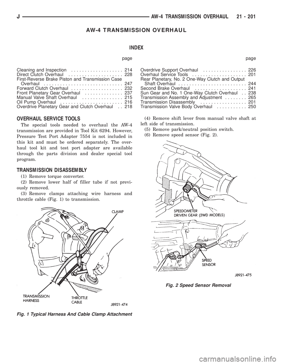
(3) Remove clamps attaching wire harness and
throttle cable (Fig. 1) to transmission.(4) Remove shift lever from manual valve shaft at
left side of transmission.
(5) Remove park/neutral position switch.
(6) Remove speed sensor (Fig. 2).
Fig. 1 Typical Harness And Cable Clamp Attachment
Fig. 2 Speed Sensor Removal
JAW-4 TRANSMISSION OVERHAUL 21 - 201
Page 1642 of 2198
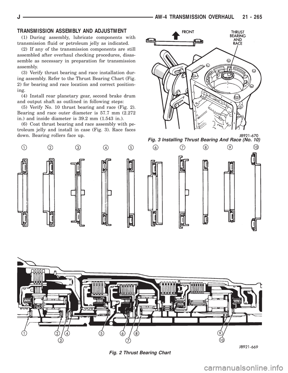
TRANSMISSION ASSEMBLY AND ADJUSTMENT
(1) During assembly, lubricate components with
transmission fluid or petroleum jelly as indicated.
(2) If any of the transmission components are still
assembled after overhaul checking procedures, disas-
semble as necessary in preparation for transmission
assembly.
(3) Verify thrust bearing and race installation dur-
ing assembly. Refer to the Thrust Bearing Chart (Fig.
2) for bearing and race location and correct position-
ing.
(4) Install rear planetary gear, second brake drum
and output shaft as outlined in following steps:
(5) Verify No. 10 thrust bearing and race (Fig. 2).
Bearing and race outer diameter is 57.7 mm (2.272
in.) and inside diameter is 39.2 mm (1.543 in.).
(6) Coat thrust bearing and race assembly with pe-
troleum jelly and install in case (Fig. 3). Race faces
down. Bearing rollers face up.
Fig. 2 Thrust Bearing Chart
Fig. 3 Installing Thrust Bearing And Race (No. 10)
JAW-4 TRANSMISSION OVERHAUL 21 - 265
Page 1658 of 2198
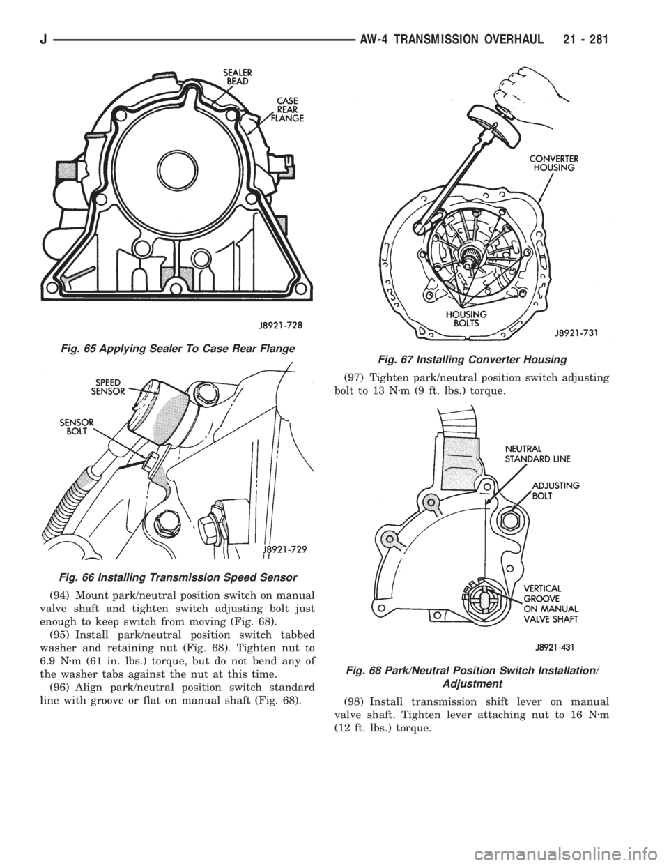
(94) Mount park/neutral position switch on manual
valve shaft and tighten switch adjusting bolt just
enough to keep switch from moving (Fig. 68).
(95) Install park/neutral position switch tabbed
washer and retaining nut (Fig. 68). Tighten nut to
6.9 Nzm (61 in. lbs.) torque, but do not bend any of
the washer tabs against the nut at this time.
(96) Align park/neutral position switch standard
line with groove or flat on manual shaft (Fig. 68).(97) Tighten park/neutral position switch adjusting
bolt to 13 Nzm (9 ft. lbs.) torque.
(98) Install transmission shift lever on manual
valve shaft. Tighten lever attaching nut to 16 Nzm
(12 ft. lbs.) torque.
Fig. 65 Applying Sealer To Case Rear Flange
Fig. 66 Installing Transmission Speed Sensor
Fig. 67 Installing Converter Housing
Fig. 68 Park/Neutral Position Switch Installation/
Adjustment
JAW-4 TRANSMISSION OVERHAUL 21 - 281
Page 1663 of 2198
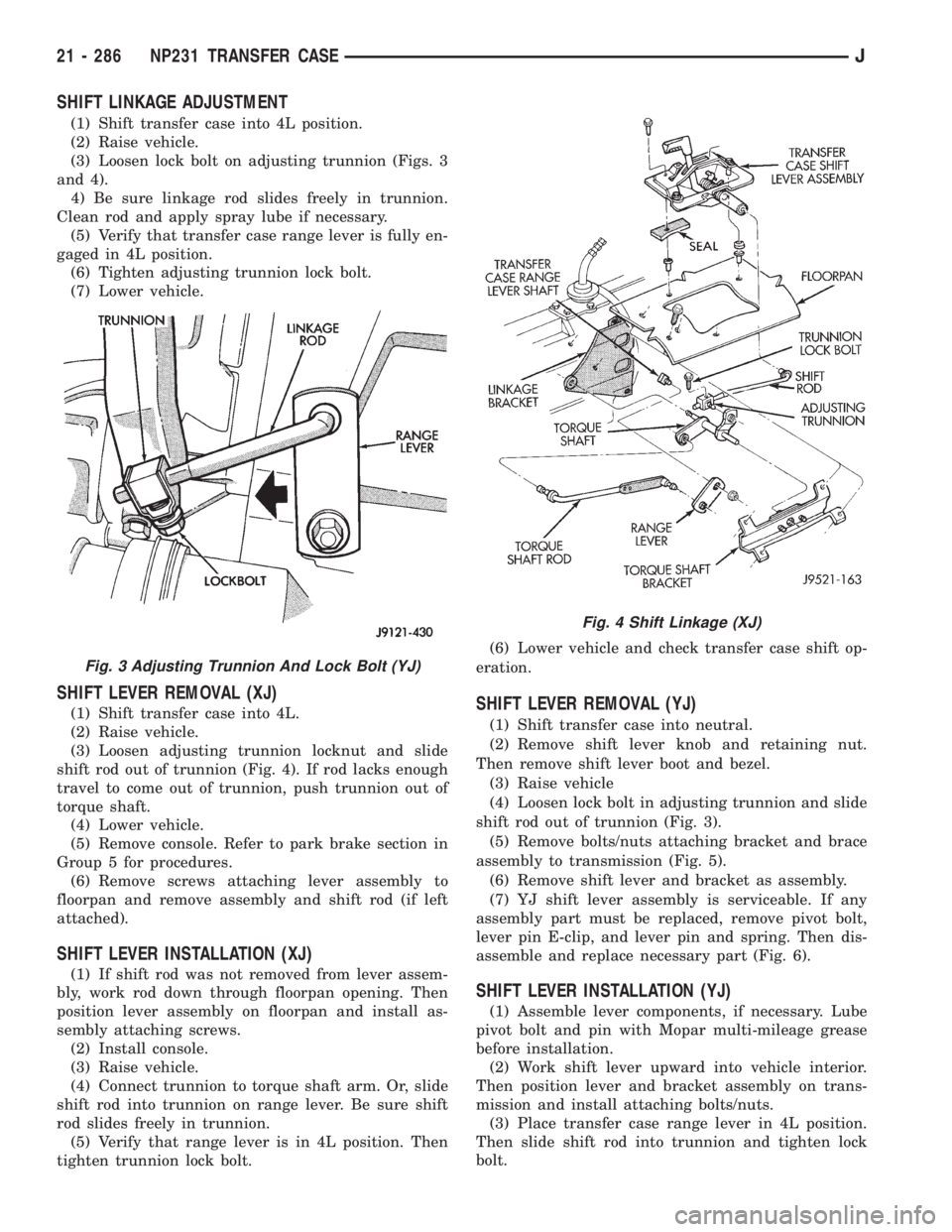
SHIFT LINKAGE ADJUSTMENT
(1) Shift transfer case into 4L position.
(2) Raise vehicle.
(3) Loosen lock bolt on adjusting trunnion (Figs. 3
and 4).
4) Be sure linkage rod slides freely in trunnion.
Clean rod and apply spray lube if necessary.
(5) Verify that transfer case range lever is fully en-
gaged in 4L position.
(6) Tighten adjusting trunnion lock bolt.
(7) Lower vehicle.
SHIFT LEVER REMOVAL (XJ)
(1) Shift transfer case into 4L.
(2) Raise vehicle.
(3) Loosen adjusting trunnion locknut and slide
shift rod out of trunnion (Fig. 4). If rod lacks enough
travel to come out of trunnion, push trunnion out of
torque shaft.
(4) Lower vehicle.
(5) Remove console. Refer to park brake section in
Group 5 for procedures.
(6) Remove screws attaching lever assembly to
floorpan and remove assembly and shift rod (if left
attached).
SHIFT LEVER INSTALLATION (XJ)
(1) If shift rod was not removed from lever assem-
bly, work rod down through floorpan opening. Then
position lever assembly on floorpan and install as-
sembly attaching screws.
(2) Install console.
(3) Raise vehicle.
(4) Connect trunnion to torque shaft arm. Or, slide
shift rod into trunnion on range lever. Be sure shift
rod slides freely in trunnion.
(5) Verify that range lever is in 4L position. Then
tighten trunnion lock bolt.(6) Lower vehicle and check transfer case shift op-
eration.
SHIFT LEVER REMOVAL (YJ)
(1) Shift transfer case into neutral.
(2) Remove shift lever knob and retaining nut.
Then remove shift lever boot and bezel.
(3) Raise vehicle
(4) Loosen lock bolt in adjusting trunnion and slide
shift rod out of trunnion (Fig. 3).
(5) Remove bolts/nuts attaching bracket and brace
assembly to transmission (Fig. 5).
(6) Remove shift lever and bracket as assembly.
(7) YJ shift lever assembly is serviceable. If any
assembly part must be replaced, remove pivot bolt,
lever pin E-clip, and lever pin and spring. Then dis-
assemble and replace necessary part (Fig. 6).
SHIFT LEVER INSTALLATION (YJ)
(1) Assemble lever components, if necessary. Lube
pivot bolt and pin with Mopar multi-mileage grease
before installation.
(2) Work shift lever upward into vehicle interior.
Then position lever and bracket assembly on trans-
mission and install attaching bolts/nuts.
(3) Place transfer case range lever in 4L position.
Then slide shift rod into trunnion and tighten lock
bolt.
Fig. 3 Adjusting Trunnion And Lock Bolt (YJ)
Fig. 4 Shift Linkage (XJ)
21 - 286 NP231 TRANSFER CASEJ
Page 1686 of 2198
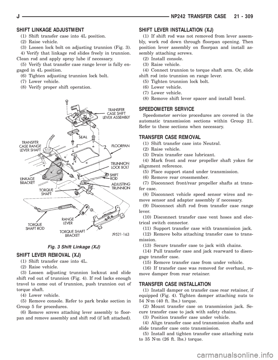
SHIFT LINKAGE ADJUSTMENT
(1) Shift transfer case into 4L position.
(2) Raise vehicle.
(3) Loosen lock bolt on adjusting trunnion (Fig. 3).
4) Verify that linkage rod slides freely in trunnion.
Clean rod and apply spray lube if necessary.
(5) Verify that transfer case range lever is fully en-
gaged in 4L position.
(6) Tighten adjusting trunnion lock bolt.
(7) Lower vehicle.
(8) Verify proper shift operation.
SHIFT LEVER REMOVAL (XJ)
(1) Shift transfer case into 4L.
(2) Raise vehicle.
(3) Loosen adjusting trunnion locknut and slide
shift rod out of trunnion (Fig. 4). If rod lacks enough
travel to come out of trunnion, push trunnion out of
torque shaft.
(4) Lower vehicle.
(5) Remove console. Refer to park brake section in
Group 5 for procedures.
(6) Remove screws attaching lever assembly to floor-
pan and remove assembly and shift rod (if left attached).
SHIFT LEVER INSTALLATION (XJ)
(1) If shift rod was not removed from lever assem-
bly, work rod down through floorpan opening. Then
position lever assembly on floorpan and install as-
sembly attaching screws.
(2) Install console.
(3) Raise vehicle.
(4) Connect trunnion to torque shaft arm. Or, slide
shift rod into trunnion on range lever.
(5) Tighten trunnion lock bolt.
(6) Lower vehicle.
(7) Lower vehicle.
(8) Remove shift lever spacer and install bezel.
SPEEDOMETER SERVICE
Speedometer service procedures are covered in the
automatic transmission sections within Group 21.
Refer to these sections when necessary.
TRANSFER CASE REMOVAL
(1) Shift transfer case into Neutral.
(2) Raise vehicle.
(3) Drain transfer case lubricant.
(4) Mark front and rear propeller shaft yokes for
alignment reference.
(5) Place support stand under transmission.
(6) Remove rear crossmember.
(7) Disconnect front/rear propeller shafts at trans-
fer case.
(8) Disconnect vehicle speed sensor wires and re-
move sensor and adapter assembly if necessary.
(9) Disconnect shift rod from transfer case range
lever.
(10) Disconnect transfer case vent hoses and elec-
trical switch connector.
(11) Support transfer case with transmission jack.
(12) Remove bolts attaching transfer case to trans-
mission.
(13) Secure transfer case to jack with chains.
(14) Pull transfer case and jack rearward to disen-
gage transfer case.
(15) Remove transfer case from under vehicle.
(16) If transfer case was removed for overhaul, re-
move damper from rear retainer.
TRANSFER CASE INSTALLATION
(1) Install damper on transfer case rear retainer, if
equipped (Fig. 4). Tighten damper attaching nuts to
54 Nzm (40 ft. lbs.) torque.
(2) Mount transfer case on transmission jack. Se-
cure transfer case to jack with safety chains.
(3) Position transfer case under vehicle.
(4) Align transfer case and transmission shafts and
slide transfer case onto transmission.
(5) Install and tighten transfer case attaching nuts
to 35 Nzm (26 ft. lbs.) torque.
Fig. 3 Shift Linkage (XJ)
JNP242 TRANSFER CASE 21 - 309