1995 JEEP CHEROKEE torque
[x] Cancel search: torquePage 1195 of 2198
CAUTION: When disconnecting the cruise control
connector at the throttle body, DO NOT pry the con-
nector off with pliers or screwdriver. Use finger
pressure only. Prying the connector off could break
it.
(9) Disconnect the electrical connectors. Pull the
harnesses away from the manifold.
²The throttle position sensor.
²The idle speed control motor.
²The coolant temperature sensor at the thermostat.
²The manifold air temperature sensor at the intake
manifold.
²The fuel injectors.
²The oxygen sensor.
(10) Disconnect the crankcase ventilation (CCV)
vacuum hose and manifold absolute pressure (MAP)
sensor vacuum hose connector at the intake mani-
fold.
(11) Disconnect vacuum hose from vacuum port on
the intake manifold.
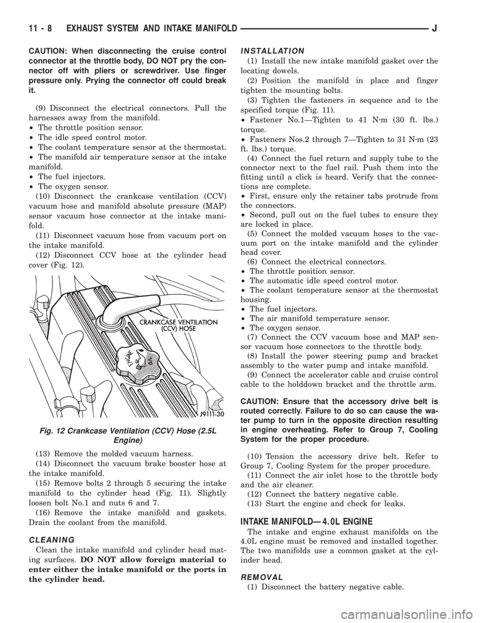
(12) Disconnect CCV hose at the cylinder head
cover (Fig. 12).
(13) Remove the molded vacuum harness.
(14) Disconnect the vacuum brake booster hose at
the intake manifold.
(15) Remove bolts 2 through 5 securing the intake
manifold to the cylinder head (Fig. 11). Slightly
loosen bolt No.1 and nuts 6 and 7.
(16) Remove the intake manifold and gaskets.
Drain the coolant from the manifold.
CLEANING
Clean the intake manifold and cylinder head mat-
ing surfaces.DO NOT allow foreign material to
enter either the intake manifold or the ports in
the cylinder head.
INSTALLATION
(1) Install the new intake manifold gasket over the
locating dowels.
(2) Position the manifold in place and finger
tighten the mounting bolts.
(3) Tighten the fasteners in sequence and to the
specified torque (Fig. 11).
²Fastener No.1ÐTighten to 41 Nzm (30 ft. lbs.)
torque.
²Fasteners Nos.2 through 7ÐTighten to 31 Nzm (23
ft. lbs.) torque.
(4) Connect the fuel return and supply tube to the
connector next to the fuel rail. Push them into the
fitting until a click is heard. Verify that the connec-
tions are complete.
²First, ensure only the retainer tabs protrude from
the connectors.
²Second, pull out on the fuel tubes to ensure they
are locked in place.
(5) Connect the molded vacuum hoses to the vac-
uum port on the intake manifold and the cylinder
head cover.
(6) Connect the electrical connectors.
²The throttle position sensor.
²The automatic idle speed control motor.
²The coolant temperature sensor at the thermostat
housing.
²The fuel injectors.
²The air manifold temperature sensor.
²The oxygen sensor.
(7) Connect the CCV vacuum hose and MAP sen-
sor vacuum hose connectors to the throttle body.
(8) Install the power steering pump and bracket
assembly to the water pump and intake manifold.
(9) Connect the accelerator cable and cruise control
cable to the holddown bracket and the throttle arm.
CAUTION: Ensure that the accessory drive belt is
routed correctly. Failure to do so can cause the wa-
ter pump to turn in the opposite direction resulting
in engine overheating. Refer to Group 7, Cooling
System for the proper procedure.
(10) Tension the accessory drive belt. Refer to
Group 7, Cooling System for the proper procedure.
(11) Connect the air inlet hose to the throttle body
and the air cleaner.
(12) Connect the battery negative cable.
(13) Start the engine and check for leaks.
INTAKE MANIFOLDÐ4.0L ENGINE
The intake and engine exhaust manifolds on the
4.0L engine must be removed and installed together.
The two manifolds use a common gasket at the cyl-
inder head.
REMOVAL
(1) Disconnect the battery negative cable.
Fig. 12 Crankcase Ventilation (CCV) Hose (2.5L
Engine)
11 - 8 EXHAUST SYSTEM AND INTAKE MANIFOLDJ
Page 1196 of 2198
(2) Remove air cleaner inlet hose from throttle
plate assembly.
(3) Remove the air cleaner assembly.
(4) Remove the throttle cable, cruise control cable
(if equipped) and the transmission line pressure ca-
ble.
(5) Disconnect all electrical connectors on the in-
take manifold.
(6) Disconnect and remove the fuel supply and re-
turn lines from the fuel rail assembly (refer to Group
14, Fuel System).
(7) Loosen the accessory drive belt (refer to Group
7, Cooling System). Loosen the tensioner.
(8) Remove the power steering pump and bracket
from the intake manifold and set aside.
(9) Remove the fuel rail and injectors (refer to
Group 14, Fuel System).
(10) Raise the vehicle.
(11) Disconnect the exhaust pipe from the engine
exhaust manifold. Discard the seal.
(12) Lower the vehicle.
(13) Remove the intake manifold and engine ex-
haust manifold.
CLEANING
Clean the mating surfaces of the cylinder head and
the manifold if the original manifold is to be in-
stalled.
If the manifold is being replaced, ensure all the fit-
ting, etc. are transferred to the replacement mani-
fold.
INSTALLATION
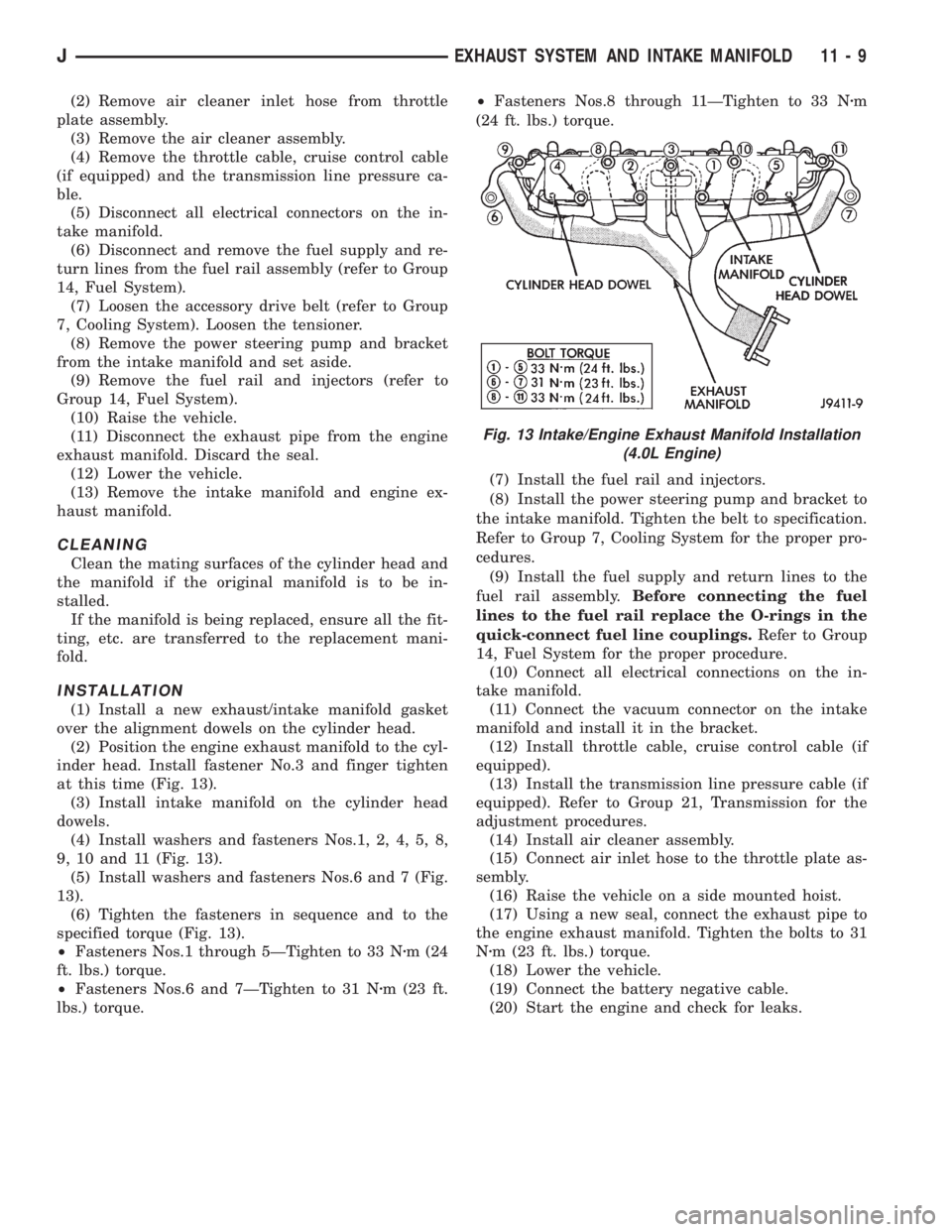
(1) Install a new exhaust/intake manifold gasket
over the alignment dowels on the cylinder head.
(2) Position the engine exhaust manifold to the cyl-
inder head. Install fastener No.3 and finger tighten
at this time (Fig. 13).
(3) Install intake manifold on the cylinder head
dowels.
(4) Install washers and fasteners Nos.1, 2, 4, 5, 8,
9, 10 and 11 (Fig. 13).
(5) Install washers and fasteners Nos.6 and 7 (Fig.
13).
(6) Tighten the fasteners in sequence and to the
specified torque (Fig. 13).
²Fasteners Nos.1 through 5ÐTighten to 33 Nzm (24
ft. lbs.) torque.
²Fasteners Nos.6 and 7ÐTighten to 31 Nzm (23 ft.
lbs.) torque.²Fasteners Nos.8 through 11ÐTighten to 33 Nzm
(24 ft. lbs.) torque.
(7) Install the fuel rail and injectors.
(8) Install the power steering pump and bracket to
the intake manifold. Tighten the belt to specification.
Refer to Group 7, Cooling System for the proper pro-
cedures.
(9) Install the fuel supply and return lines to the
fuel rail assembly.Before connecting the fuel
lines to the fuel rail replace the O-rings in the
quick-connect fuel line couplings.Refer to Group
14, Fuel System for the proper procedure.
(10) Connect all electrical connections on the in-
take manifold.
(11) Connect the vacuum connector on the intake
manifold and install it in the bracket.
(12) Install throttle cable, cruise control cable (if
equipped).
(13) Install the transmission line pressure cable (if
equipped). Refer to Group 21, Transmission for the
adjustment procedures.
(14) Install air cleaner assembly.
(15) Connect air inlet hose to the throttle plate as-
sembly.
(16) Raise the vehicle on a side mounted hoist.
(17) Using a new seal, connect the exhaust pipe to
the engine exhaust manifold. Tighten the bolts to 31
Nzm (23 ft. lbs.) torque.
(18) Lower the vehicle.
(19) Connect the battery negative cable.
(20) Start the engine and check for leaks.
Fig. 13 Intake/Engine Exhaust Manifold Installation
(4.0L Engine)
JEXHAUST SYSTEM AND INTAKE MANIFOLD 11 - 9
Page 1197 of 2198
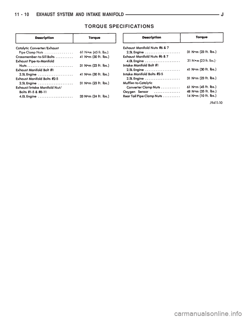
TORQUE SPECIFICATIONS
11 - 10 EXHAUST SYSTEM AND INTAKE MANIFOLDJ
Page 1200 of 2198
TRANSFER CASE SKID PLATE
REMOVAL
(1) Support the skid plate.
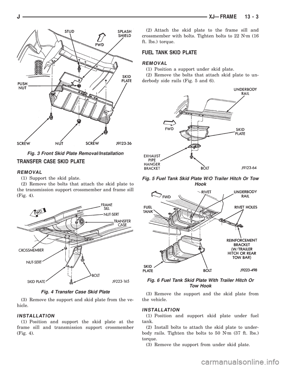
(2) Remove the bolts that attach the skid plate to
the transmission support crossmember and frame sill
(Fig. 4).
(3) Remove the support and skid plate from the ve-
hicle.
INSTALLATION
(1) Position and support the skid plate at the
frame sill and transmission support crossmember
(Fig. 4).(2) Attach the skid plate to the frame sill and
crossmember with bolts. Tighten bolts to 22 Nzm (16
ft. lbs.) torque.
FUEL TANK SKID PLATE
REMOVAL
(1) Position a support under skid plate.
(2) Remove the bolts that attach skid plate to un-
derbody side rails (Fig. 5 and 6).
(3) Remove the support and the skid plate from
the vehicle.
INSTALLATION
(1) Position and support skid plate under fuel
tank.
(2) Install bolts to attach the skid plate to under-
body rails. Tighten the bolts to 50 Nzm (37 ft. lbs.)
torque.
(3) Remove the support from under skid plate.
Fig. 3 Front Skid Plate Removal/Installation
Fig. 4 Transfer Case Skid Plate
Fig. 5 Fuel Tank Skid Plate W/O Trailer Hitch Or Tow
Hook
Fig. 6 Fuel Tank Skid Plate With Trailer Hitch Or
Tow Hook
JXJÐFRAME 13 - 3
Page 1201 of 2198
FUEL FILLER HOSE SPLASH SHIELDÐXJ
VEHICLES
REMOVAL
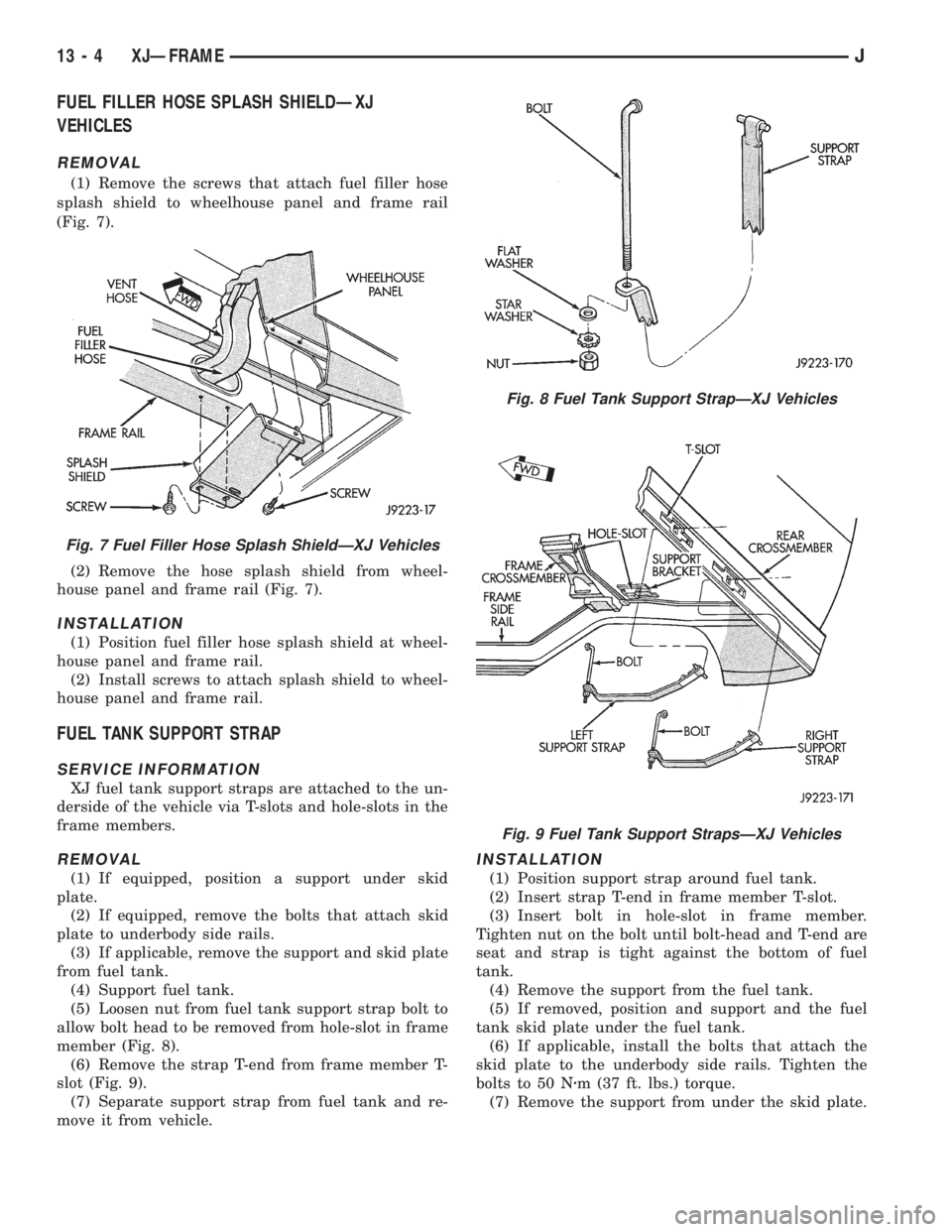
(1) Remove the screws that attach fuel filler hose
splash shield to wheelhouse panel and frame rail
(Fig. 7).
(2) Remove the hose splash shield from wheel-
house panel and frame rail (Fig. 7).
INSTALLATION
(1) Position fuel filler hose splash shield at wheel-
house panel and frame rail.
(2) Install screws to attach splash shield to wheel-
house panel and frame rail.
FUEL TANK SUPPORT STRAP
SERVICE INFORMATION
XJ fuel tank support straps are attached to the un-
derside of the vehicle via T-slots and hole-slots in the
frame members.
REMOVAL
(1) If equipped, position a support under skid
plate.
(2) If equipped, remove the bolts that attach skid
plate to underbody side rails.
(3) If applicable, remove the support and skid plate
from fuel tank.
(4) Support fuel tank.
(5) Loosen nut from fuel tank support strap bolt to
allow bolt head to be removed from hole-slot in frame
member (Fig. 8).
(6) Remove the strap T-end from frame member T-
slot (Fig. 9).
(7) Separate support strap from fuel tank and re-
move it from vehicle.
INSTALLATION
(1) Position support strap around fuel tank.
(2) Insert strap T-end in frame member T-slot.
(3) Insert bolt in hole-slot in frame member.
Tighten nut on the bolt until bolt-head and T-end are
seat and strap is tight against the bottom of fuel
tank.
(4) Remove the support from the fuel tank.
(5) If removed, position and support and the fuel
tank skid plate under the fuel tank.
(6) If applicable, install the bolts that attach the
skid plate to the underbody side rails. Tighten the
bolts to 50 Nzm (37 ft. lbs.) torque.
(7) Remove the support from under the skid plate.
Fig. 7 Fuel Filler Hose Splash ShieldÐXJ Vehicles
Fig. 8 Fuel Tank Support StrapÐXJ Vehicles
Fig. 9 Fuel Tank Support StrapsÐXJ Vehicles
13 - 4 XJÐFRAMEJ
Page 1204 of 2198
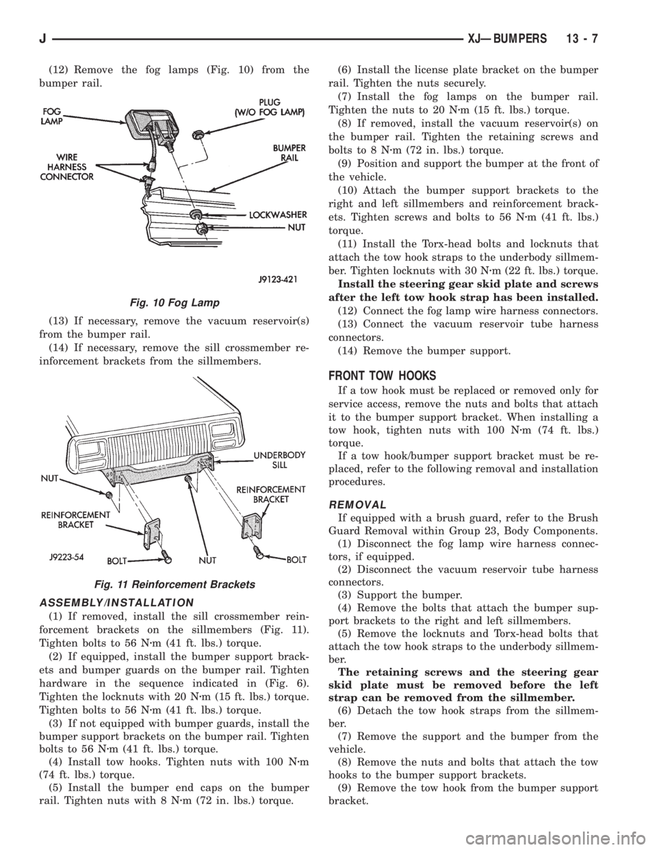
(12) Remove the fog lamps (Fig. 10) from the
bumper rail.
(13) If necessary, remove the vacuum reservoir(s)
from the bumper rail.
(14) If necessary, remove the sill crossmember re-
inforcement brackets from the sillmembers.
ASSEMBLY/INSTALLATION
(1) If removed, install the sill crossmember rein-
forcement brackets on the sillmembers (Fig. 11).
Tighten bolts to 56 Nzm (41 ft. lbs.) torque.
(2) If equipped, install the bumper support brack-
ets and bumper guards on the bumper rail. Tighten
hardware in the sequence indicated in (Fig. 6).
Tighten the locknuts with 20 Nzm (15 ft. lbs.) torque.
Tighten bolts to 56 Nzm (41 ft. lbs.) torque.
(3) If not equipped with bumper guards, install the
bumper support brackets on the bumper rail. Tighten
bolts to 56 Nzm (41 ft. lbs.) torque.
(4) Install tow hooks. Tighten nuts with 100 Nzm
(74 ft. lbs.) torque.
(5) Install the bumper end caps on the bumper
rail. Tighten nuts with 8 Nzm (72 in. lbs.) torque.(6) Install the license plate bracket on the bumper
rail. Tighten the nuts securely.
(7) Install the fog lamps on the bumper rail.
Tighten the nuts to 20 Nzm (15 ft. lbs.) torque.
(8) If removed, install the vacuum reservoir(s) on
the bumper rail. Tighten the retaining screws and
bolts to 8 Nzm (72 in. lbs.) torque.
(9) Position and support the bumper at the front of
the vehicle.
(10) Attach the bumper support brackets to the
right and left sillmembers and reinforcement brack-
ets. Tighten screws and bolts to 56 Nzm (41 ft. lbs.)
torque.
(11) Install the Torx-head bolts and locknuts that
attach the tow hook straps to the underbody sillmem-
ber. Tighten locknuts with 30 Nzm (22 ft. lbs.) torque.
Install the steering gear skid plate and screws
after the left tow hook strap has been installed.
(12) Connect the fog lamp wire harness connectors.
(13) Connect the vacuum reservoir tube harness
connectors.
(14) Remove the bumper support.
FRONT TOW HOOKS
If a tow hook must be replaced or removed only for
service access, remove the nuts and bolts that attach
it to the bumper support bracket. When installing a
tow hook, tighten nuts with 100 Nzm (74 ft. lbs.)
torque.
If a tow hook/bumper support bracket must be re-
placed, refer to the following removal and installation
procedures.
REMOVAL
If equipped with a brush guard, refer to the Brush
Guard Removal within Group 23, Body Components.
(1) Disconnect the fog lamp wire harness connec-
tors, if equipped.
(2) Disconnect the vacuum reservoir tube harness
connectors.
(3) Support the bumper.
(4) Remove the bolts that attach the bumper sup-
port brackets to the right and left sillmembers.
(5) Remove the locknuts and Torx-head bolts that
attach the tow hook straps to the underbody sillmem-
ber.
The retaining screws and the steering gear
skid plate must be removed before the left
strap can be removed from the sillmember.
(6) Detach the tow hook straps from the sillmem-
ber.
(7) Remove the support and the bumper from the
vehicle.
(8) Remove the nuts and bolts that attach the tow
hooks to the bumper support brackets.
(9) Remove the tow hook from the bumper support
bracket.
Fig. 10 Fog Lamp
Fig. 11 Reinforcement Brackets
JXJÐBUMPERS 13 - 7
Page 1205 of 2198
(10) Remove the support bracket from the bumper
rail.
INSTALLATION
(1) Install the bumper guard and bumper support
bracket on the bumper rail. Tighten the retaining
hardware in the sequence indicated in Figure 7.
Tighten locknuts to 20 Nzm (15 ft. lbs.) torque.
Tighten bolts to 56 Nzm (41 ft. lbs.) torque.
(2) If not equipped with bumper guards, install the
bumper support bracket on the bumper rail. Tighten
bolts to 56 Nzm (41 ft. lbs.) torque.
(3) Position the tow hook at the support bracket.
Install the bolts and nuts that attach tow hook to the
bumper support bracket. Tighten nuts to 100 Nzm (74
ft. lbs.) torque.
(4) Position and support the bumper at the front of
the vehicle.
(5) Attach the bumper support brackets to the
right and left sillmembers and reinforcement brack-
ets. Tighten screws and bolts to 56 Nzm (41 ft. lbs.)
torque.
(6) Install the Torx-head bolts and locknuts that
attach the tow hook straps to the underbody sillmem-
ber. Tighten locknuts to 30 Nzm (22 ft. lbs.) torque.
Install the steering gear skid plate and screws
after the left tow hook strap has been installed.
(7) Connect the fog lamp wire harness connectors.
Connect the vacuum reservoir tube harness connec-
tors.
(8) Remove the bumper support.
REAR BUMPER
REMOVAL
(1) For vehicles equipped with a trailer hitch, re-
move the hitch before removing the bumper. If neces-
sary, refer to the removal procedure within Group 23,
Body Components.
(2) Raise and support the rear of the vehicle.
(3) Support the bumper.
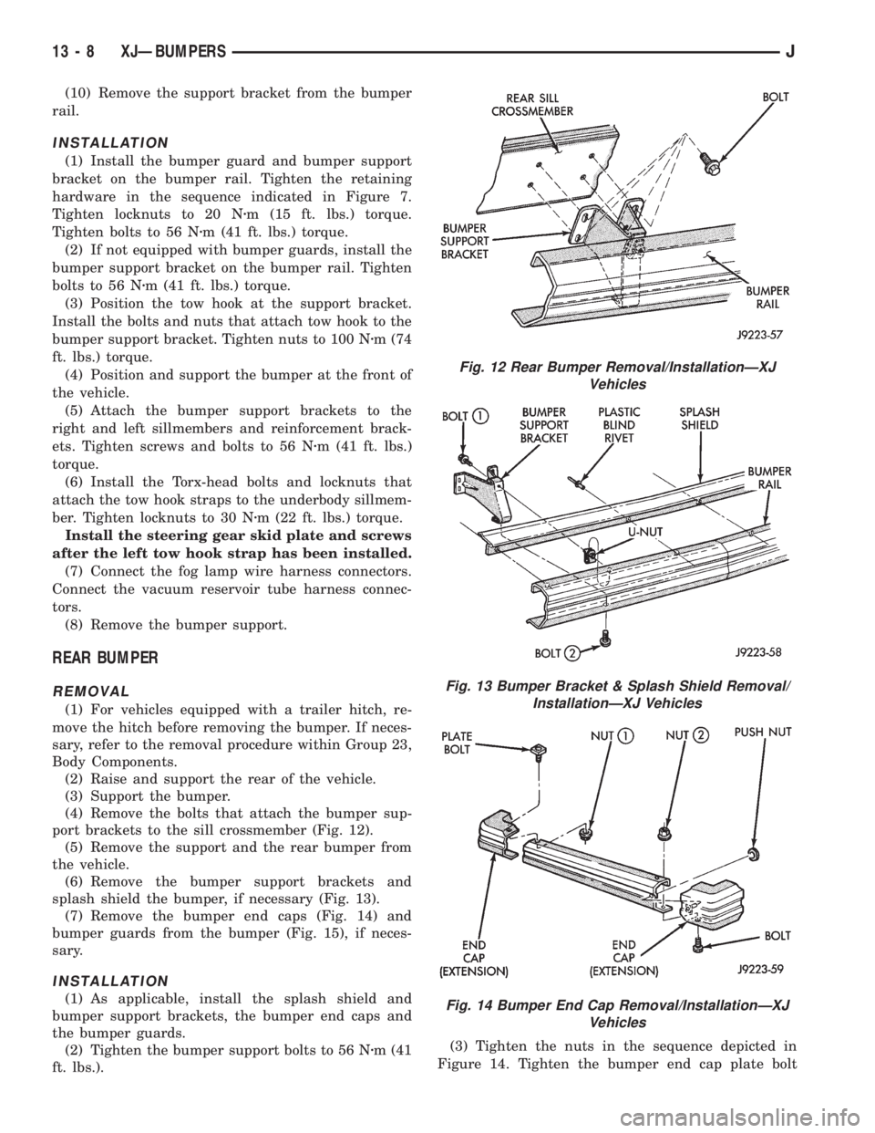
(4) Remove the bolts that attach the bumper sup-
port brackets to the sill crossmember (Fig. 12).
(5) Remove the support and the rear bumper from
the vehicle.
(6) Remove the bumper support brackets and
splash shield the bumper, if necessary (Fig. 13).
(7) Remove the bumper end caps (Fig. 14) and
bumper guards from the bumper (Fig. 15), if neces-
sary.
INSTALLATION
(1) As applicable, install the splash shield and
bumper support brackets, the bumper end caps and
the bumper guards.
(2) Tighten the bumper support bolts to 56 Nzm (41
ft. lbs.).(3) Tighten the nuts in the sequence depicted in
Figure 14. Tighten the bumper end cap plate bolt
Fig. 12 Rear Bumper Removal/InstallationÐXJ
Vehicles
Fig. 13 Bumper Bracket & Splash Shield Removal/
InstallationÐXJ Vehicles
Fig. 14 Bumper End Cap Removal/InstallationÐXJ
Vehicles
13 - 8 XJÐBUMPERSJ
Page 1206 of 2198
nuts to 22 Nzm (16 ft. lbs.) torque. Tighten the lower
bolt nuts to 8 Nzm (6 ft. lbs.) torque.
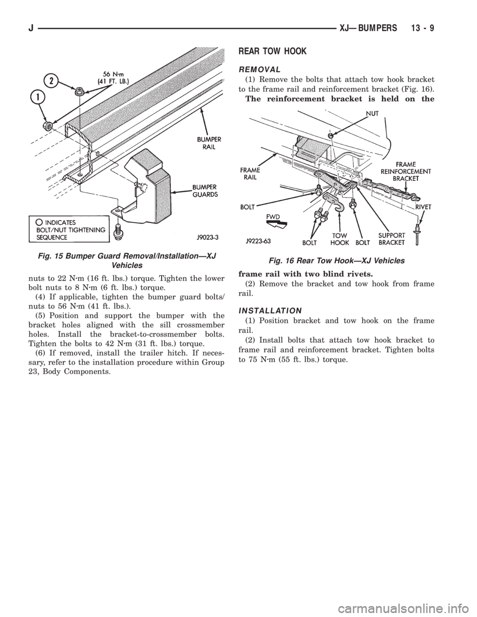
(4) If applicable, tighten the bumper guard bolts/
nuts to 56 Nzm (41 ft. lbs.).
(5) Position and support the bumper with the
bracket holes aligned with the sill crossmember
holes. Install the bracket-to-crossmember bolts.
Tighten the bolts to 42 Nzm (31 ft. lbs.) torque.
(6) If removed, install the trailer hitch. If neces-
sary, refer to the installation procedure within Group
23, Body Components.
REAR TOW HOOK
REMOVAL
(1) Remove the bolts that attach tow hook bracket
to the frame rail and reinforcement bracket (Fig. 16).
The reinforcement bracket is held on the
frame rail with two blind rivets.
(2) Remove the bracket and tow hook from frame
rail.
INSTALLATION
(1) Position bracket and tow hook on the frame
rail.
(2) Install bolts that attach tow hook bracket to
frame rail and reinforcement bracket. Tighten bolts
to 75 Nzm (55 ft. lbs.) torque.
Fig. 15 Bumper Guard Removal/InstallationÐXJ
VehiclesFig. 16 Rear Tow HookÐXJ Vehicles
JXJÐBUMPERS 13 - 9