1995 JEEP CHEROKEE torque
[x] Cancel search: torquePage 1282 of 2198
speedometer pinion gear adapter (Fig. 29). Do not re-
move the gear adapter from the transmission.
INSTALLATION
(1) Clean the inside of speedometer pinion gear
adapter before installing speed sensor.
(2) Install sensor into speedometer gear adapter
and install mounting bolt.Before tightening bolt,verify speed sensor is fully seated (mounted
flush) to speedometer pinion gear adapter.
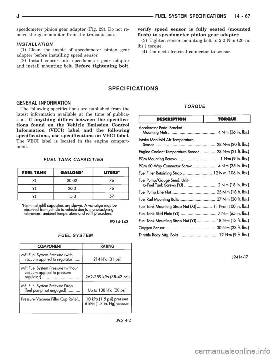
(3) Tighten sensor mounting bolt to 2.2 Nzm (20 in.
lbs.) torque.
(4) Connect electrical connector to sensor.
SPECIFICATIONS
GENERAL INFORMATION
The following specifications are published from the
latest information available at the time of publica-
tion.If anything differs between the specifica-
tions found on the Vehicle Emission Control
Information (VECI) label and the following
specifications, use specifications on VECI label.
The VECI label is located in the engine compart-
ment.
FUEL TANK CAPACITIES
FUEL SYSTEM
TORQUE
JFUEL SYSTEM SPECIFICATIONS 14 - 67
Page 1284 of 2198
PROPELLER SHAFTS
CONTENTS
page page
GENERAL INFORMATION.................. 1
SERVICE DIAGNOSIS..................... 3
SERVICE PROCEDURES................... 8TORQUE SPECIFICATIONS................ 15
UNIVERSAL JOINT REPLACEMENT......... 10
GENERAL INFORMATION
PROPELLER SHAFTS
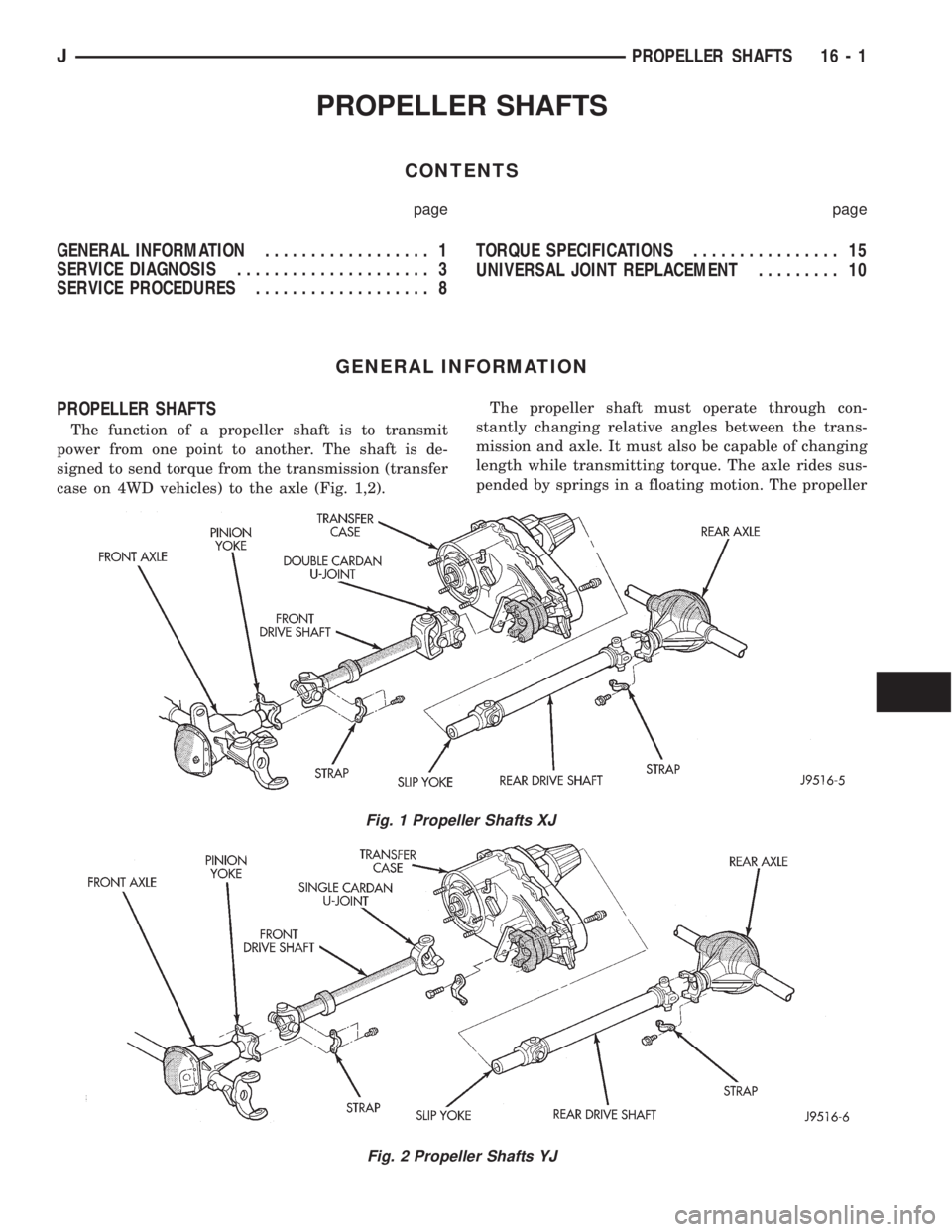
The function of a propeller shaft is to transmit
power from one point to another. The shaft is de-
signed to send torque from the transmission (transfer
case on 4WD vehicles) to the axle (Fig. 1,2).The propeller shaft must operate through con-
stantly changing relative angles between the trans-
mission and axle. It must also be capable of changing
length while transmitting torque. The axle rides sus-
pended by springs in a floating motion. The propeller
Fig. 1 Propeller Shafts XJ
Fig. 2 Propeller Shafts YJ
JPROPELLER SHAFTS 16 - 1
Page 1285 of 2198
shaft must be able to change operating angles when
going over various road surfaces. This is done
through universal joints, which permit the propeller
shaft to operate at different angles. The slip joints (or
yokes) permit contraction or expansion (Fig. 1,2).
Tubular propeller shafts are balanced by the man-
ufacturer with weights spot welded to the tube.
The propeller shaft is designed and built with the
yoke lugs in line with each other which is called
phasing. This design produces the smoothest running
condition, an out of phase shaft can cause a vibra-
tion.
Before undercoating a vehicle, the propeller
shaft and the U-joints should be covered. This
will prevent the undercoating from causing an
unbalanced condition and vibration.
CAUTION: Use exact replacement hardware for at-
taching the propeller shafts. The specified torque
must always be applied when tightening the fasten-
ers.
UNIVERSAL JOINTS
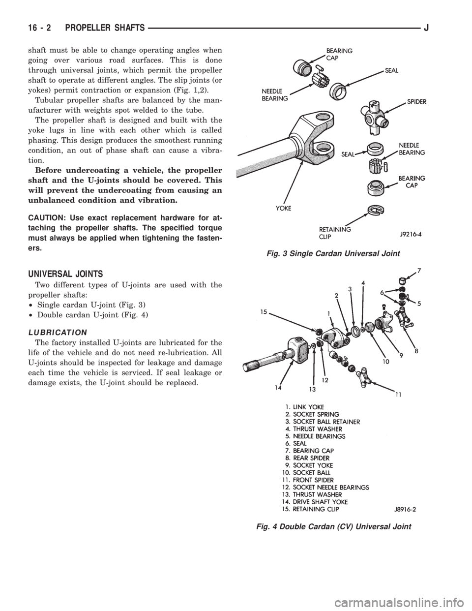
Two different types of U-joints are used with the
propeller shafts:
²Single cardan U-joint (Fig. 3)
²Double cardan U-joint (Fig. 4)
LUBRICATION
The factory installed U-joints are lubricated for the
life of the vehicle and do not need re-lubrication. All
U-joints should be inspected for leakage and damage
each time the vehicle is serviced. If seal leakage or
damage exists, the U-joint should be replaced.
Fig. 3 Single Cardan Universal Joint
Fig. 4 Double Cardan (CV) Universal Joint
16 - 2 PROPELLER SHAFTSJ
Page 1286 of 2198
SERVICE DIAGNOSIS
INDEX
page page
Runout.................................. 4
Unbalance............................... 3Universal Joint Angle Measurement............. 4
Vibration................................. 3
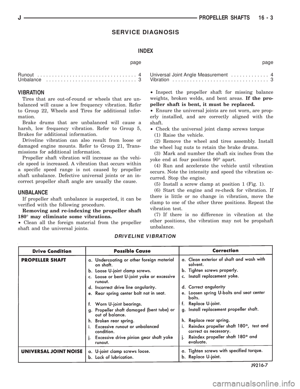
VIBRATION
Tires that are out-of-round or wheels that are un-
balanced will cause a low frequency vibration. Refer
to Group 22, Wheels and Tires for additional infor-
mation.
Brake drums that are unbalanced will cause a
harsh, low frequency vibration. Refer to Group 5,
Brakes for additional information.
Driveline vibration can also result from loose or
damaged engine mounts. Refer to Group 21, Trans-
missions for additional information.
Propeller shaft vibration will increase as the vehi-
cle speed is increased. A vibration that occurs within
a specific speed range is not caused by propeller
shaft unbalance. Defective universal joints or an in-
correct propeller shaft angle are usually the cause.
UNBALANCE
If propeller shaft unbalance is suspected, it can be
verified with the following procedure.
Removing and re-indexing the propeller shaft
180É may eliminate some vibrations.
²Clean all the foreign material from the propeller
shaft and the universal joints.²Inspect the propeller shaft for missing balance
weights, broken welds, and bent areas.If the pro-
peller shaft is bent, it must be replaced.
²Ensure the universal joints are not worn, are prop-
erly installed, and are correctly aligned with the
shaft.
²Check the universal joint clamp screws torque
(1) Raise the vehicle.
(2) Remove the wheel and tires assembly. Install
the wheel lug nuts to retain the brake drums.
(3) Mark and number the shaft six inches from the
yoke end at four positions 90É apart.
(4) Run and accelerate the vehicle until vibration
occurs. Note the intensity and speed the vibration oc-
curred. Stop the engine.
(5) Install a screw clamp at position 1 (Fig. 1).
(6) Start the engine and re-check for vibration. If
there is little or no change in vibration, move the
clamp to one of the other three positions. Repeat the
vibration test.
(7) If there is no difference in vibration at the
other positions, the vibration may not be propshaft
unbalance.
DRIVELINE VIBRATION
JPROPELLER SHAFTS 16 - 3
Page 1288 of 2198
²Have at least a 1/2 degree continuous operating
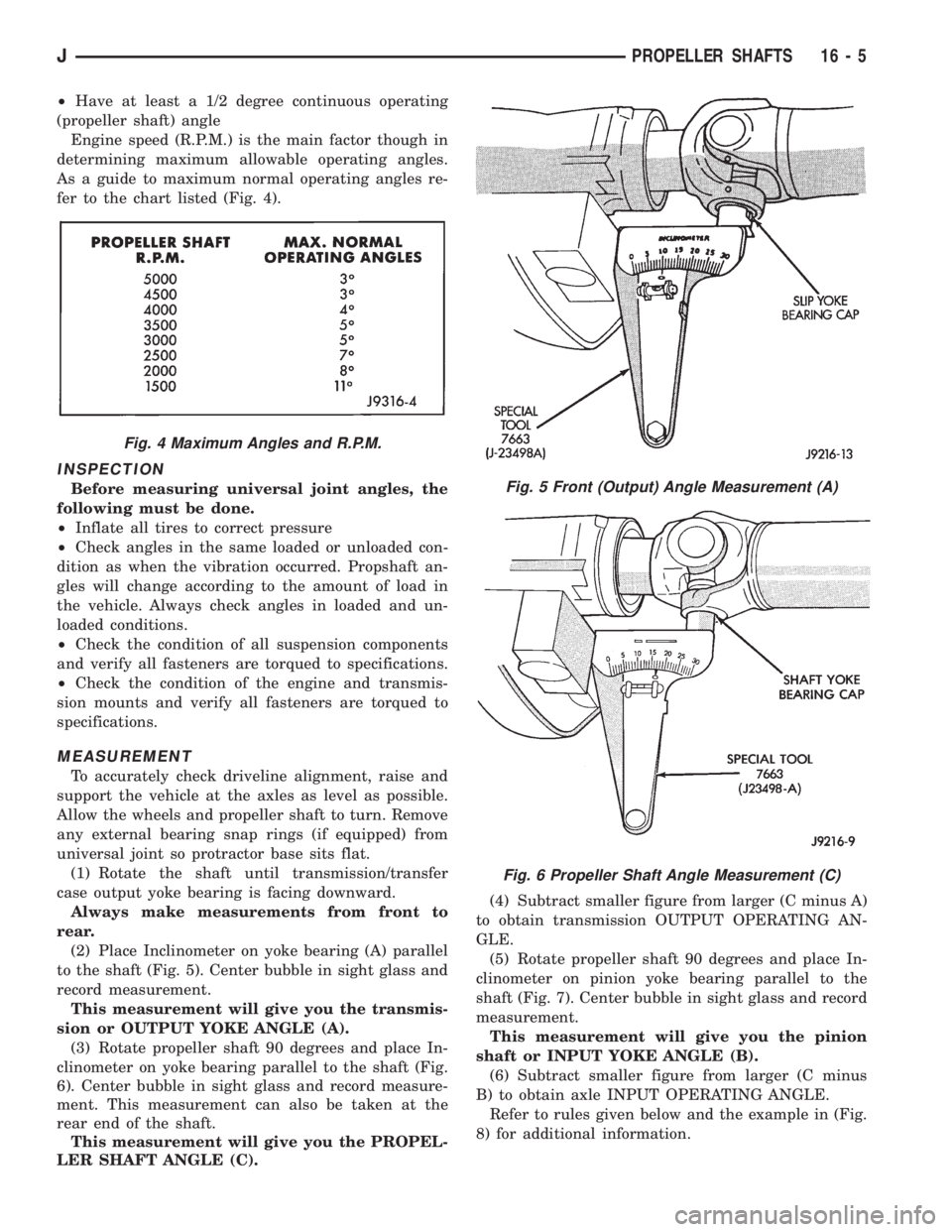
(propeller shaft) angle
Engine speed (R.P.M.) is the main factor though in
determining maximum allowable operating angles.
As a guide to maximum normal operating angles re-
fer to the chart listed (Fig. 4).
INSPECTION
Before measuring universal joint angles, the
following must be done.
²Inflate all tires to correct pressure
²Check angles in the same loaded or unloaded con-
dition as when the vibration occurred. Propshaft an-
gles will change according to the amount of load in
the vehicle. Always check angles in loaded and un-
loaded conditions.
²Check the condition of all suspension components
and verify all fasteners are torqued to specifications.
²Check the condition of the engine and transmis-
sion mounts and verify all fasteners are torqued to
specifications.
MEASUREMENT
To accurately check driveline alignment, raise and
support the vehicle at the axles as level as possible.
Allow the wheels and propeller shaft to turn. Remove
any external bearing snap rings (if equipped) from
universal joint so protractor base sits flat.
(1) Rotate the shaft until transmission/transfer
case output yoke bearing is facing downward.
Always make measurements from front to
rear.
(2) Place Inclinometer on yoke bearing (A) parallel
to the shaft (Fig. 5). Center bubble in sight glass and
record measurement.
This measurement will give you the transmis-
sion or OUTPUT YOKE ANGLE (A).
(3) Rotate propeller shaft 90 degrees and place In-
clinometer on yoke bearing parallel to the shaft (Fig.
6). Center bubble in sight glass and record measure-
ment. This measurement can also be taken at the
rear end of the shaft.
This measurement will give you the PROPEL-
LER SHAFT ANGLE (C).(4) Subtract smaller figure from larger (C minus A)
to obtain transmission OUTPUT OPERATING AN-
GLE.
(5) Rotate propeller shaft 90 degrees and place In-
clinometer on pinion yoke bearing parallel to the
shaft (Fig. 7). Center bubble in sight glass and record
measurement.
This measurement will give you the pinion
shaft or INPUT YOKE ANGLE (B).
(6) Subtract smaller figure from larger (C minus
B) to obtain axle INPUT OPERATING ANGLE.
Refer to rules given below and the example in (Fig.
8) for additional information.
Fig. 4 Maximum Angles and R.P.M.
Fig. 5 Front (Output) Angle Measurement (A)
Fig. 6 Propeller Shaft Angle Measurement (C)
JPROPELLER SHAFTS 16 - 5
Page 1291 of 2198
SERVICE PROCEDURES
PRECAUTIONS
Use exact replacement hardware for attaching the
propeller shafts. Exact replacement will ensure safe
operation. The specified torque must always be ap-
plied when tightening the fasteners.
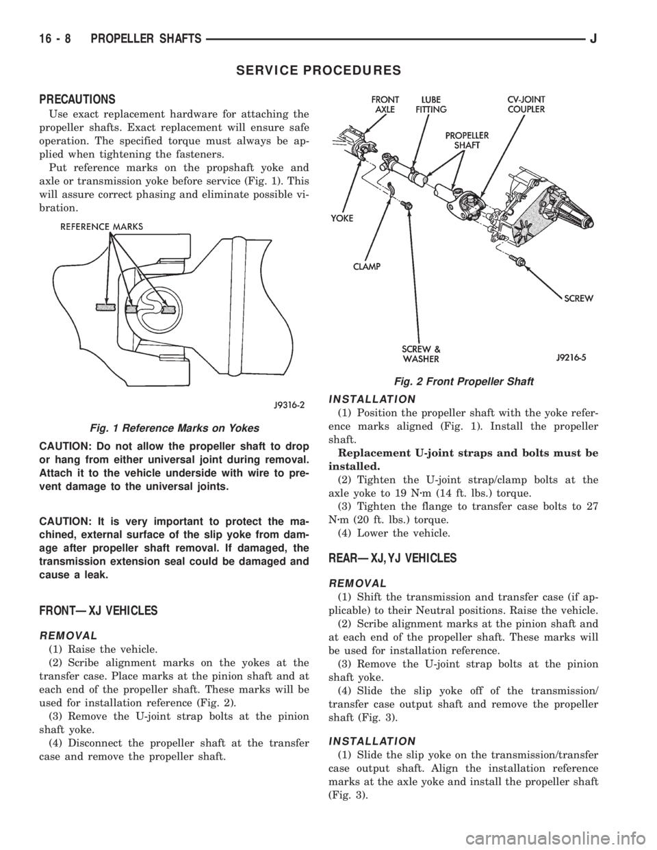
Put reference marks on the propshaft yoke and
axle or transmission yoke before service (Fig. 1). This
will assure correct phasing and eliminate possible vi-
bration.
CAUTION: Do not allow the propeller shaft to drop
or hang from either universal joint during removal.
Attach it to the vehicle underside with wire to pre-
vent damage to the universal joints.
CAUTION: It is very important to protect the ma-
chined, external surface of the slip yoke from dam-
age after propeller shaft removal. If damaged, the
transmission extension seal could be damaged and
cause a leak.
FRONTÐXJ VEHICLES
REMOVAL
(1) Raise the vehicle.
(2) Scribe alignment marks on the yokes at the
transfer case. Place marks at the pinion shaft and at
each end of the propeller shaft. These marks will be
used for installation reference (Fig. 2).
(3) Remove the U-joint strap bolts at the pinion
shaft yoke.
(4) Disconnect the propeller shaft at the transfer
case and remove the propeller shaft.
INSTALLATION
(1) Position the propeller shaft with the yoke refer-
ence marks aligned (Fig. 1). Install the propeller
shaft.
Replacement U-joint straps and bolts must be
installed.
(2) Tighten the U-joint strap/clamp bolts at the
axle yoke to 19 Nzm (14 ft. lbs.) torque.
(3) Tighten the flange to transfer case bolts to 27
Nzm (20 ft. lbs.) torque.
(4) Lower the vehicle.
REARÐXJ,YJ VEHICLES
REMOVAL
(1) Shift the transmission and transfer case (if ap-
plicable) to their Neutral positions. Raise the vehicle.
(2) Scribe alignment marks at the pinion shaft and
at each end of the propeller shaft. These marks will
be used for installation reference.
(3) Remove the U-joint strap bolts at the pinion
shaft yoke.
(4) Slide the slip yoke off of the transmission/
transfer case output shaft and remove the propeller
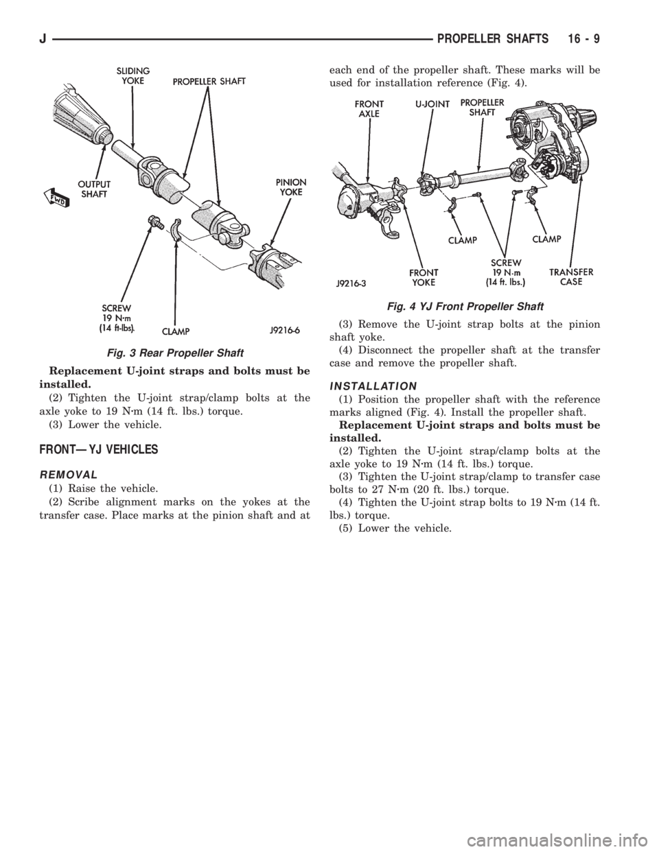
shaft (Fig. 3).
INSTALLATION
(1) Slide the slip yoke on the transmission/transfer
case output shaft. Align the installation reference
marks at the axle yoke and install the propeller shaft
(Fig. 3).
Fig. 1 Reference Marks on Yokes
Fig. 2 Front Propeller Shaft
16 - 8 PROPELLER SHAFTSJ
Page 1292 of 2198
Replacement U-joint straps and bolts must be
installed.
(2) Tighten the U-joint strap/clamp bolts at the
axle yoke to 19 Nzm (14 ft. lbs.) torque.
(3) Lower the vehicle.
FRONTÐYJ VEHICLES
REMOVAL
(1) Raise the vehicle.
(2) Scribe alignment marks on the yokes at the
transfer case. Place marks at the pinion shaft and ateach end of the propeller shaft. These marks will be
used for installation reference (Fig. 4).
(3) Remove the U-joint strap bolts at the pinion
shaft yoke.
(4) Disconnect the propeller shaft at the transfer
case and remove the propeller shaft.
INSTALLATION
(1) Position the propeller shaft with the reference
marks aligned (Fig. 4). Install the propeller shaft.
Replacement U-joint straps and bolts must be
installed.
(2) Tighten the U-joint strap/clamp bolts at the
axle yoke to 19 Nzm (14 ft. lbs.) torque.
(3) Tighten the U-joint strap/clamp to transfer case
bolts to 27 Nzm (20 ft. lbs.) torque.
(4) Tighten the U-joint strap bolts to 19 Nzm (14 ft.
lbs.) torque.
(5) Lower the vehicle.
Fig. 3 Rear Propeller Shaft
Fig. 4 YJ Front Propeller Shaft
JPROPELLER SHAFTS 16 - 9
Page 1298 of 2198
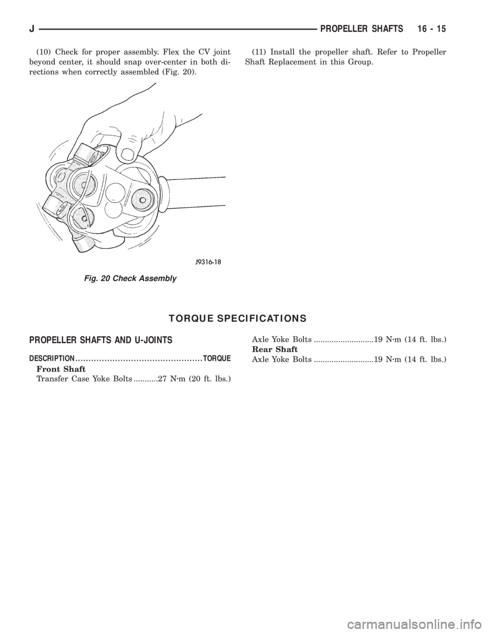
(10) Check for proper assembly. Flex the CV joint
beyond center, it should snap over-center in both di-
rections when correctly assembled (Fig. 20).(11) Install the propeller shaft. Refer to Propeller
Shaft Replacement in this Group.
TORQUE SPECIFICATIONS
PROPELLER SHAFTS AND U-JOINTS
DESCRIPTION ................................................TORQUE
Front Shaft
Transfer Case Yoke Bolts ...........27 Nzm (20 ft. lbs.)Axle Yoke Bolts ...........................19 Nzm (14 ft. lbs.)
Rear Shaft
Axle Yoke Bolts ...........................19 Nzm (14 ft. lbs.)
Fig. 20 Check Assembly
JPROPELLER SHAFTS 16 - 15