1995 JEEP CHEROKEE torque
[x] Cancel search: torquePage 1353 of 2198
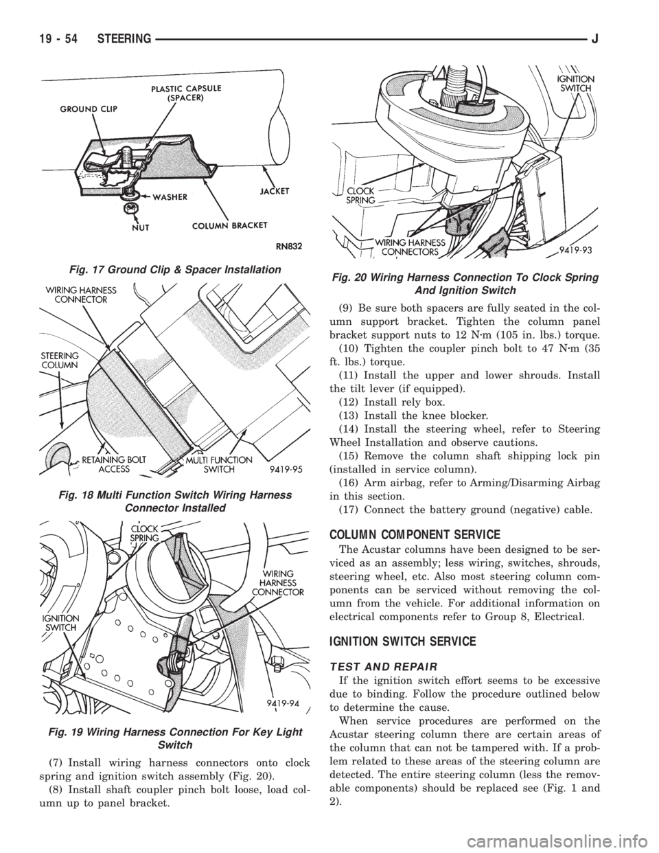
(7) Install wiring harness connectors onto clock
spring and ignition switch assembly (Fig. 20).
(8) Install shaft coupler pinch bolt loose, load col-
umn up to panel bracket.(9) Be sure both spacers are fully seated in the col-
umn support bracket. Tighten the column panel
bracket support nuts to 12 Nzm (105 in. lbs.) torque.
(10) Tighten the coupler pinch bolt to 47 Nzm (35
ft. lbs.) torque.
(11) Install the upper and lower shrouds. Install
the tilt lever (if equipped).
(12) Install rely box.
(13) Install the knee blocker.
(14) Install the steering wheel, refer to Steering
Wheel Installation and observe cautions.
(15) Remove the column shaft shipping lock pin
(installed in service column).
(16) Arm airbag, refer to Arming/Disarming Airbag
in this section.
(17) Connect the battery ground (negative) cable.
COLUMN COMPONENT SERVICE
The Acustar columns have been designed to be ser-
viced as an assembly; less wiring, switches, shrouds,
steering wheel, etc. Also most steering column com-
ponents can be serviced without removing the col-
umn from the vehicle. For additional information on
electrical components refer to Group 8, Electrical.
IGNITION SWITCH SERVICE
TEST AND REPAIR
If the ignition switch effort seems to be excessive
due to binding. Follow the procedure outlined below
to determine the cause.
When service procedures are performed on the
Acustar steering column there are certain areas of
the column that can not be tampered with. If a prob-
lem related to these areas of the steering column are
detected. The entire steering column (less the remov-
able components) should be replaced see (Fig. 1 and
2).
Fig. 17 Ground Clip & Spacer Installation
Fig. 18 Multi Function Switch Wiring Harness
Connector Installed
Fig. 19 Wiring Harness Connection For Key Light
Switch
Fig. 20 Wiring Harness Connection To Clock Spring
And Ignition Switch
19 - 54 STEERINGJ
Page 1357 of 2198
STEERING COLUMNÐYJ
INDEX
page page
Assembly............................... 63
Assembly............................... 71
Column Replacement...................... 58
Disassembly............................. 66DisassemblyÐColumn or Console Shift......... 60
Non-Tilt Steering Column................... 60
Steering Wheel........................... 58
Tilt Steering Column....................... 66
The column may be disassembled and reassembled.
Also most steering column components can be serviced
without removing the column from the vehicle. For ad-
ditional information, refer to Group 8H, Electrical.
CAUTION: Bumping, jolting and hammering on the
steering column shaft and gear shift tube must be
avoided during all service procedures.
CAUTION: Disconnect negative (ground) cable from the
battery before servicing any component on the column.
Safety goggles should be worn at all times
when involved with steering column service.
STEERING WHEEL
REMOVAL
(1) Make sure the front wheels are in thestraight
aheadposition.
(2) Disconnect the negative (ground) cable from the
battery.
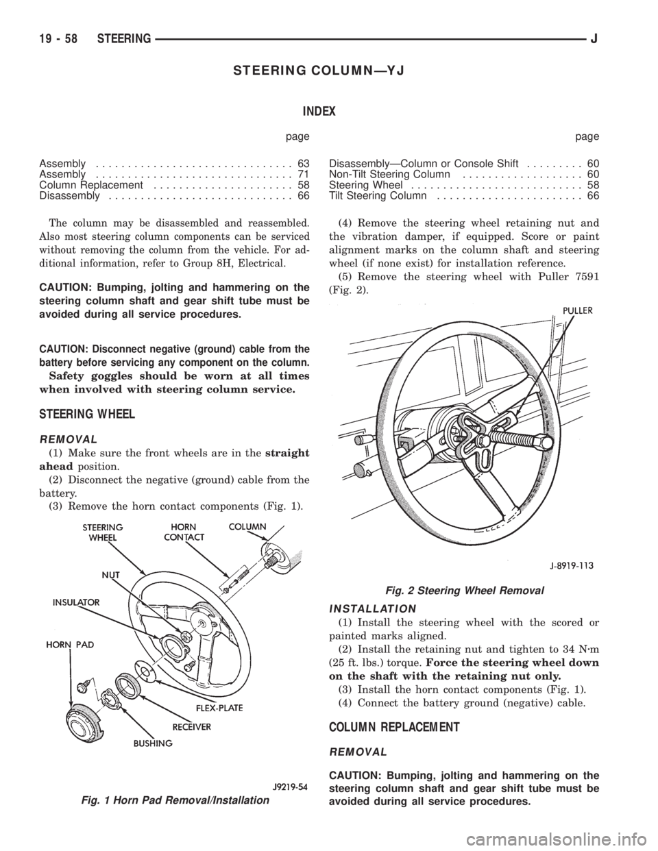
(3) Remove the horn contact components (Fig. 1).(4) Remove the steering wheel retaining nut and
the vibration damper, if equipped. Score or paint
alignment marks on the column shaft and steering
wheel (if none exist) for installation reference.
(5) Remove the steering wheel with Puller 7591
(Fig. 2).
INSTALLATION
(1) Install the steering wheel with the scored or
painted marks aligned.
(2) Install the retaining nut and tighten to 34 Nzm
(25 ft. lbs.) torque.Force the steering wheel down
on the shaft with the retaining nut only.
(3) Install the horn contact components (Fig. 1).
(4) Connect the battery ground (negative) cable.
COLUMN REPLACEMENT
REMOVAL
CAUTION: Bumping, jolting and hammering on the
steering column shaft and gear shift tube must be
avoided during all service procedures.
Fig. 1 Horn Pad Removal/Installation
Fig. 2 Steering Wheel Removal
19 - 58 STEERINGJ
Page 1358 of 2198
(1) Make sure the front wheels are in thestraight
aheadposition.
(2) Disconnect the negative (ground) cable from the
battery.
(3) Remove steering wheel from column, refer to
Steering Wheel-Removal.
(4) Column shift vehicles, disconnect the shift ca-
ble grommet by prying it from the shift lever.
(5) Disconnect the column shaft to steering gear
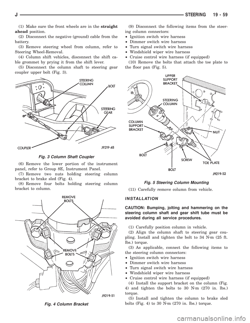
coupler upper bolt (Fig. 3).
(6) Remove the lower portion of the instrument
panel, refer to Group 8E, Instrument Panel.
(7) Remove two nuts holding steering column
bracket to brake sled (Fig. 4).
(8) Remove four bolts holding steering column
bracket to column.(9) Disconnect the following items from the steer-
ing column connectors:
²Ignition switch wire harness
²Dimmer switch wire harness
²Turn signal switch wire harness
²Windshield wiper wire harness
²Cruise control wire harness (if equipped)
(10) Remove the bolts that attach the toe plate to
the floor pan (Fig. 5).
(11) Carefully remove column from vehicle.
INSTALLATION
CAUTION: Bumping, jolting and hammering on the
steering column shaft and gear shift tube must be
avoided during all service procedures.
(1) Carefully position column in vehicle.
(2) Align the column shaft to steering gear cou-
pling. Install and tighten the bolt to 34 Nzm (25 ft.
lbs.) torque.
(3) As applicable, connect the following items to
the steering column connectors:
²Ignition switch wire harness
²Dimmer switch wire harness
²Turn signal switch wire harness
²Windshield wiper wire harness
²Cruise control wire harness (if equipped)
(4) Install the support bracket on the column (Fig.
4) and tighten the bolts to 30 Nzm (270 in. lbs.)
torque.
(5) Install and tighten the column to brake sled
bolts (Fig. 4) to 30 Nzm (270 in. lbs.) torque.
Fig. 3 Column Shaft Coupler
Fig. 4 Column Bracket
Fig. 5 Steering Column Mounting
JSTEERING 19 - 59
Page 1359 of 2198
(6) Column shift vehicles, install the shift cable
grommet on the shift lever.
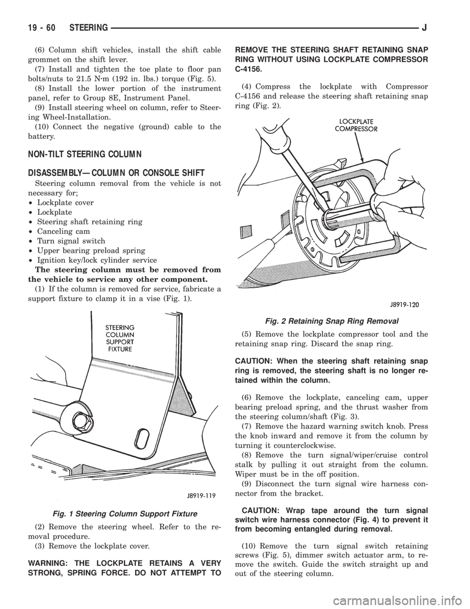
(7) Install and tighten the toe plate to floor pan
bolts/nuts to 21.5 Nzm (192 in. lbs.) torque (Fig. 5).
(8) Install the lower portion of the instrument
panel, refer to Group 8E, Instrument Panel.
(9) Install steering wheel on column, refer to Steer-
ing Wheel-Installation.
(10) Connect the negative (ground) cable to the
battery.
NON-TILT STEERING COLUMN
DISASSEMBLYÐCOLUMN OR CONSOLE SHIFT
Steering column removal from the vehicle is not
necessary for;
²Lockplate cover
²Lockplate
²Steering shaft retaining ring
²Canceling cam
²Turn signal switch
²Upper bearing preload spring
²Ignition key/lock cylinder service
The steering column must be removed from
the vehicle to service any other component.
(1) If the column is removed for service, fabricate a
support fixture to clamp it in a vise (Fig. 1).
(2) Remove the steering wheel. Refer to the re-
moval procedure.
(3) Remove the lockplate cover.
WARNING: THE LOCKPLATE RETAINS A VERY
STRONG, SPRING FORCE. DO NOT ATTEMPT TOREMOVE THE STEERING SHAFT RETAINING SNAP
RING WITHOUT USING LOCKPLATE COMPRESSOR
C-4156.
(4) Compress the lockplate with Compressor
C-4156 and release the steering shaft retaining snap
ring (Fig. 2).
(5) Remove the lockplate compressor tool and the
retaining snap ring. Discard the snap ring.
CAUTION: When the steering shaft retaining snap
ring is removed, the steering shaft is no longer re-
tained within the column.
(6) Remove the lockplate, canceling cam, upper
bearing preload spring, and the thrust washer from
the steering column/shaft (Fig. 3).
(7) Remove the hazard warning switch knob. Press
the knob inward and remove it from the column by
turning it counterclockwise.
(8) Remove the turn signal/wiper/cruise control
stalk by pulling it out straight from the column.
Wiper must be in the off position.
(9) Disconnect the turn signal wire harness con-
nector from the bracket.
CAUTION: Wrap tape around the turn signal
switch wire harness connector (Fig. 4) to prevent it
from becoming entangled during removal.
(10) Remove the turn signal switch retaining
screws (Fig. 5), dimmer switch actuator arm, to re-
move the switch. Guide the switch straight up and
out of the steering column.
Fig. 1 Steering Column Support Fixture
Fig. 2 Retaining Snap Ring Removal
19 - 60 STEERINGJ
Page 1362 of 2198
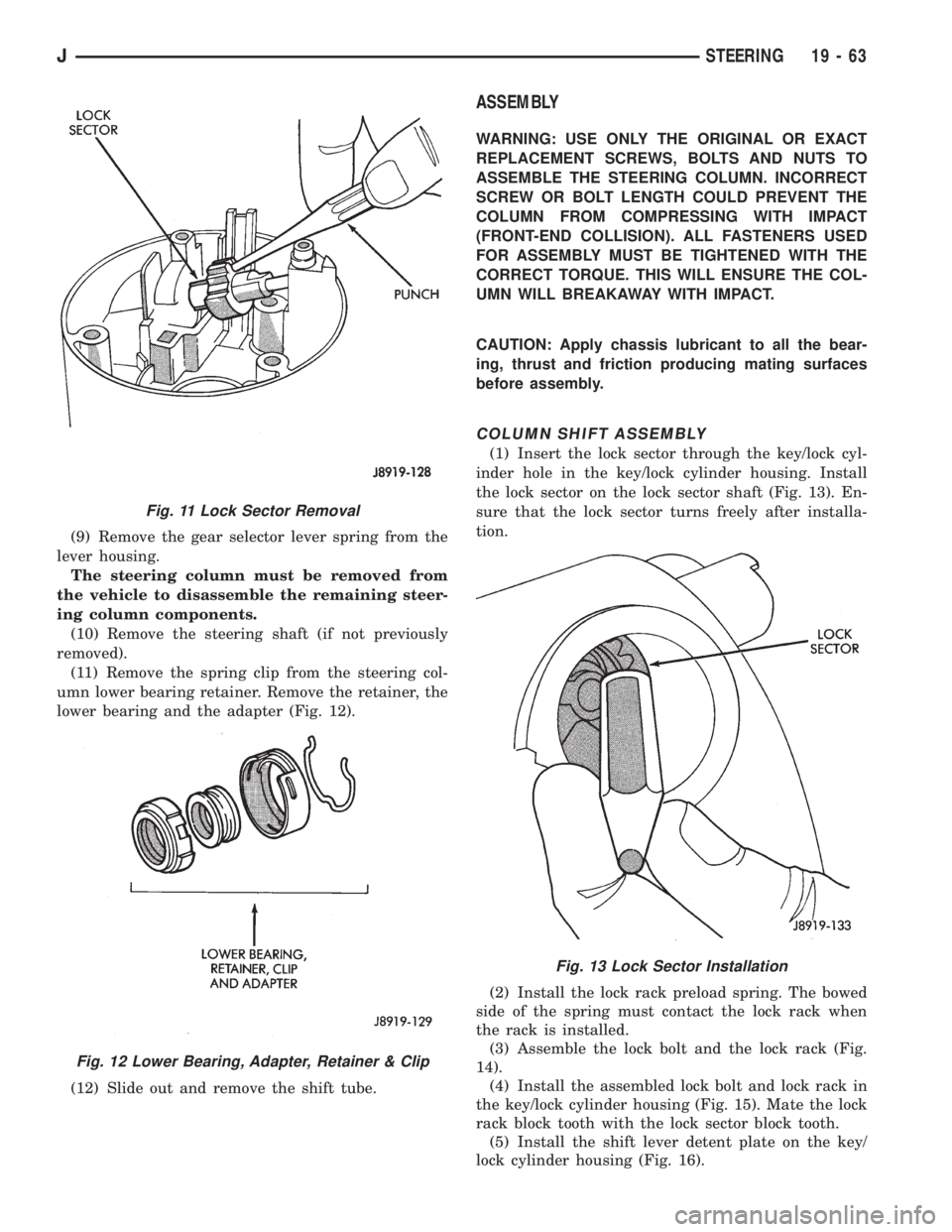
(9) Remove the gear selector lever spring from the
lever housing.
The steering column must be removed from
the vehicle to disassemble the remaining steer-
ing column components.
(10) Remove the steering shaft (if not previously
removed).
(11) Remove the spring clip from the steering col-
umn lower bearing retainer. Remove the retainer, the
lower bearing and the adapter (Fig. 12).
(12) Slide out and remove the shift tube.
ASSEMBLY
WARNING: USE ONLY THE ORIGINAL OR EXACT
REPLACEMENT SCREWS, BOLTS AND NUTS TO
ASSEMBLE THE STEERING COLUMN. INCORRECT
SCREW OR BOLT LENGTH COULD PREVENT THE
COLUMN FROM COMPRESSING WITH IMPACT
(FRONT-END COLLISION). ALL FASTENERS USED
FOR ASSEMBLY MUST BE TIGHTENED WITH THE
CORRECT TORQUE. THIS WILL ENSURE THE COL-
UMN WILL BREAKAWAY WITH IMPACT.
CAUTION: Apply chassis lubricant to all the bear-
ing, thrust and friction producing mating surfaces
before assembly.
COLUMN SHIFT ASSEMBLY
(1) Insert the lock sector through the key/lock cyl-
inder hole in the key/lock cylinder housing. Install
the lock sector on the lock sector shaft (Fig. 13). En-
sure that the lock sector turns freely after installa-
tion.
(2) Install the lock rack preload spring. The bowed
side of the spring must contact the lock rack when
the rack is installed.
(3) Assemble the lock bolt and the lock rack (Fig.
14).
(4) Install the assembled lock bolt and lock rack in
the key/lock cylinder housing (Fig. 15). Mate the lock
rack block tooth with the lock sector block tooth.
(5) Install the shift lever detent plate on the key/
lock cylinder housing (Fig. 16).
Fig. 11 Lock Sector Removal
Fig. 12 Lower Bearing, Adapter, Retainer & Clip
Fig. 13 Lock Sector Installation
JSTEERING 19 - 63
Page 1364 of 2198
(6) Position the turn signal switch and wire har-
ness in the cylinder housing. Fold the wires against
the connector. Route the connector down through the
steering column jacket.
(7) Install the windshield wiper wire harness and
switch. Route the wire harness down through steer-
ing column jacket.
(8) Align the turn signal switch in the housing and
secure the switch with the attaching screws. Tighten
the screws to 4 Nzm (35 in. lbs.) torque.
(9) Install the dimmer switch actuator arm.
Tighten the attaching screws to 4 Nzm (35 in. lbs.)
torque.
(10) If equipped, install the cruise control wire har-
ness. Install the turn signal stalk by pushing it
straight into the column.
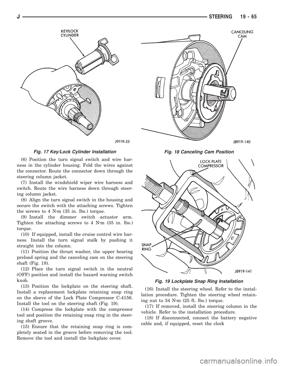
(11) Position the thrust washer, the upper bearing
preload spring and the canceling cam on the steering
shaft (Fig. 18).
(12) Place the turn signal switch in the neutral
(OFF) position and install the hazard warning switch
knob.
(13) Position the lockplate on the steering shaft.
Install a replacement lockplate retaining snap ring
on the sleeve of the Lock Plate Compressor C-4156.
Install the tool on the steering shaft (Fig. 19).
(14) Compress the lockplate with the compressor
tool and position the retaining snap ring in the steer-
ing shaft groove.
(15) Ensure that the retaining snap ring is com-
pletely seated in the groove before removing the tool.
Remove the tool and install the lockplate cover.(16) Install the steering wheel. Refer to the instal-
lation procedure. Tighten the steering wheel retain-
ing nut to 34 Nzm (25 ft. lbs.) torque.
(17) If removed, install the steering column in the
vehicle. Refer to the installation procedure.
(18) If disconnected, connect the battery negative
cable and, if equipped, reset the clock
Fig. 17 Key/Lock Cylinder InstallationFig. 18 Canceling Cam Position
Fig. 19 Lockplate Snap Ring Installation
JSTEERING 19 - 65
Page 1370 of 2198
(45) If equipped with a column shift:
²Remove the wave washer and the shift tube spring
²Remove the shift bowl from the steering column
jacket
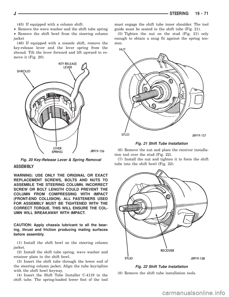
(46) If equipped with a console shift, remove the
key-release lever and the lever spring from the
shroud. Tilt the lever forward and lift upward to re-
move it (Fig. 20).
ASSEMBLY
WARNING: USE ONLY THE ORIGINAL OR EXACT
REPLACEMENT SCREWS, BOLTS AND NUTS TO
ASSEMBLE THE STEERING COLUMN. INCORRECT
SCREW OR BOLT LENGTH COULD PREVENT THE
COLUMN FROM COMPRESSING WITH IMPACT
(FRONT-END COLLISION). ALL FASTENERS USED
FOR ASSEMBLY MUST BE TIGHTENED WITH THE
CORRECT TORQUE. THIS WILL ENSURE THE COL-
UMN WILL BREAKAWAY WITH IMPACT.
CAUTION: Apply chassis lubricant to all the bear-
ing, thrust and friction producing mating surfaces
before assembly.
(1) Install the shift bowl on the steering column
jacket.
(2) Install the shift tube spring, wave washer and
retainer plate in the shift bowl.
(3) Insert the shift tube through the lower end of
the steering column jacket. Align the tube key/spline
with the shift bowl keyway.
(4) Insert the Shift Tube Installer C-4119 in the
shift tube. The spring-loaded lower foot of the toolmust engage the shift tube inner shoulder. The tool
guide must be seated in the shift tube (Fig. 21).
(5) Tighten the nut on the stud (Fig. 21) only
enough to obtain a snug fit against the spring ten-
sion.
(6) Remove the nut and place the receiver installa-
tion tool over the stud (Fig. 22).
(7) Install the nut and tighten it to force the shift
tube into the shift bowl (Fig. 22).
(8) Remove the shift tube installation tools.
Fig. 20 Key-Release Lever & Spring Removal
Fig. 21 Shift Tube Installation
Fig. 22 Shift Tube Installation
JSTEERING 19 - 71
Page 1371 of 2198
(9) Install the shift tube thrust washer and the re-
tainer plate snap ring.
(10) Install the lower bearing in the steering col-
umn.
(11) Position the shift gate in the steering column
support. Install the attaching screws.
(12) Position the support in the steering column.
(13) Install all support attaching screws finger-
tight. Next, tighten the screws alternately and evenly
to7Nzm (60 in. lbs.) torque.
(14) Install the remote rod in the support. Route
the rod through the upper end of the shroud and in-
sert it into the rod slot located in the support.
(15) Install the dimmer switch and ignition switch.
(16) Install the steering shaft in the steering col-
umn.
(17) Install replacement races and bearings in the
key/lock cylinder, if removed.Ensure that the bear-
ings are lubricated with chassis lubricant be-
fore installation.
(18) Install the lock shoes, the lock shoe springs
and the lock shoe pin the key/lock cylinder housing.
Use a 4.5-mm (0.18-in) diameter rod to align the
shoes and the pin during installation.
(19) Install the tilt-release lever, the lever spring
and the lever pin in the key/lock cylinder housing.
Insert a wedge between the housing and the lever to
relieve the spring tension. This will allow easier re-
lease lever pin installation.
(20) Install the lock bolt in the key/lock cylinder
housing and engage it in the lock sector cam surface.
(21) Install the lock rack, the rack preload spring
and a replacement shim in the key/lock cylinder
housing. Align and mate the square block tooth on
the lock rack and the lock sector.
(22) Install the lock spring and the spring retain-
ing screw. Tighten the screw to 4 Nzm (35 in. lbs.)
torque.
(23) Align and install the assembled key/lock cylin-
der housing on the support. Retain the lock shoes in
the disengaged position for easier housing installa-
tion.
(24) Align the pivot pin holes in the housing with
those in the support. Insert the pivot pins.Press the
housing firmly downward when inserting the
pivot pins. This prevents damaging the holes in
the support.When the pivot pins are within both
the housing and the support holes, seat them fully
with a punch and a hammer.
(25) Insert tilt-release lever in key/lock cylinder
housing and place housing in the full-upward tilt po-
sition.
(26) Lubricate the tilt spring guide and the tilt
spring liberally with chassis lubricant and position
the spring on the guide.
(27) Insert the tilt spring guide and the spring into
the key/lock cylinder housing. Install the guide re-tainer over the spring. Engage the retainer lock tabs
with the housing lugs by pressing the retainer down-
ward and turning clockwise with a screwdriver.
(28) Place the cover on the key/lock cylinder hous-
ing. Align and install the cover retaining screws.
Tighten the screws to 7 Nzm (60 in. lbs.) torque.
(29) Install the gear selector indicator lamp mount-
ing bracket screw.
(30) Install the gear selector indicator cover and
retaining screws.
(31) Route the dimmer switch wire harness and
gear selector indicator down through the steering col-
umn.
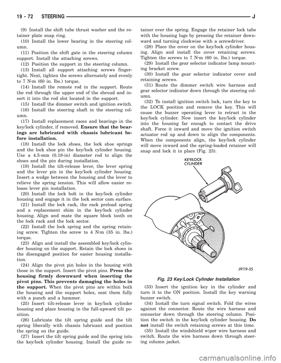
(32) To install ignition switch lock, turn the key to
the LOCK position and remove the key. This will
cause the buzzer operating lever to retract in the
key/lock cylinder. Now insert the key/lock cylinder
into the housing far enough to contact the drive
shaft. Force it inward and move the ignition switch
actuator rod up and down to align the components.
When the components align, the key/lock cylinder
will move inward and the spring-loaded retainer will
snap and lock it in place (Fig. 23).
(33) Insert the ignition key in the cylinder and
turn it to the ON position. Install the key warning
buzzer switch.
(34) Install the turn signal switch. Fold the wires
against the connector. Route the wire harness and
connector down through the steering column. Posi-
tion the switch in the key/lock cylinder housing.Do
notinstall the switch retaining screws at this time.
(35) Install the windshield wiper wire harness and
switch. Route the wire harness down through steer-
ing column jacket.
Fig. 23 Key/Lock Cylinder Installation
19 - 72 STEERINGJ