1995 JEEP CHEROKEE Coolant
[x] Cancel search: CoolantPage 1246 of 2198
²The powertrain control module (PCM) pre-posi-
tions the idle air control (IAC) motor.
²The PCM determines atmospheric air pressure
from the MAP sensor input to determine basic fuel
strategy.
²The PCM monitors the engine coolant temperature
sensor input. The PCM modifies fuel strategy based
on this input.
²Intake manifold air temperature sensor input is
monitored
²Throttle position sensor (TPS) is monitored
²The auto shutdown (ASD) relay is energized by the
PCM for approximately three seconds.
²The fuel pump is energized through the fuel pump
relay by the PCM. The fuel pump will operate for ap-
proximately three seconds unless the engine is oper-
ating or the starter motor is engaged
²The O2S sensor heater element is energized
through the fuel pump relay. The O2S sensor input is
not used by the PCM to calibrate air-fuel ratio dur-
ing this mode of operation.
²The up-shift indicator lamp is illuminated (manual
transmission only).
ENGINE START-UP MODE
This is an Open Loop mode. The following actions
occur when the starter motor is engaged.
The powertrain control module (PCM) receives in-
puts from:
²Battery voltage
²Engine coolant temperature sensor
²Crankshaft position sensor
²Intake manifold air temperature sensor
²Manifold absolute pressure (MAP) sensor
²Throttle position sensor (TPS)
²Starter motor relay
²Camshaft position sensor signal
The PCM monitors the crankshaft position sensor.
If the PCM does not receive a crankshaft position
sensor signal within 3 seconds of cranking the en-
gine, it will shut down the fuel injection system.
The fuel pump is activated by the PCM through
the fuel pump relay.
Voltage is applied to the fuel injectors with the
PCM. The PCM will then control the injection se-
quence and injector pulse width by turning the
ground circuit to each individual injector on and off.
The PCM determines the proper ignition timing ac-
cording to input received from the crankshaft posi-
tion sensor.
ENGINE WARM-UP MODE
This is an Open Loop mode. During engine warm-
up, the powertrain control module (PCM) receives in-
puts from:
²Battery voltage
²Crankshaft position sensor
²Engine coolant temperature sensor²Intake manifold air temperature sensor
²Manifold absolute pressure (MAP) sensor
²Throttle position sensor (TPS)
²Camshaft position sensor signal (in the distribu-
tor)
²Park/neutral switch (gear indicator signalÐauto.
trans. only)
²Air conditioning select signal (if equipped)
²Air conditioning request signal (if equipped)
Based on these inputs the following occurs:
²Voltage is applied to the fuel injectors with the
powertrain control module (PCM). The PCM will
then control the injection sequence and injector pulse
width by turning the ground circuit to each individ-
ual injector on and off.
²The PCM adjusts engine idle speed through the
idle air control (IAC) motor and adjusts ignition tim-
ing.
²The PCM operates the A/C compressor clutch
through the clutch relay. This is done if A/C has been
selected by the vehicle operator and requested by the
A/C thermostat.
²If the vehicle has a manual transmission, the up-
shift lamp is operated by the PCM.
²When engine has reached operating temperature,
the PCM will begin monitoring O2S sensor input.
The system will then leave the warm-up mode and go
into closed loop operation.
IDLE MODE
When the engine is at operating temperature, this
is a Closed Loop mode. At idle speed, the powertrain
control module (PCM) receives inputs from:
²Air conditioning select signal (if equipped)
²Air conditioning request signal (if equipped)
²Battery voltage
²Crankshaft position sensor
²Engine coolant temperature sensor
²Intake manifold air temperature sensor
²Manifold absolute pressure (MAP) sensor
²Throttle position sensor (TPS)
²Camshaft position sensor signal (in the distribu-
tor)
²Battery voltage
²Park/neutral switch (gear indicator signalÐauto.
trans. only)
²Oxygen sensor
Based on these inputs, the following occurs:
²Voltage is applied to the fuel injectors with the
powertrain control module (PCM). The PCM will
then control injection sequence and injector pulse
width by turning the ground circuit to each individ-
ual injector on and off.
²The PCM monitors the O2S sensor input and ad-
justs air-fuel ratio by varying injector pulse width. It
also adjusts engine idle speed through the idle air
control (IAC) motor.
JFUEL SYSTEM COMPONENT DESCRIPTION/SYSTEM OPERATION 14 - 31
Page 1247 of 2198
²The PCM adjusts ignition timing by increasing
and decreasing spark advance.
²The PCM operates the A/C compressor clutch
through the clutch relay. This happens if A/C has
been selected by the vehicle operator and requested
by the A/C thermostat.
The optional Extended Idle Switch is used to raise
the engine idle speed to approximately 1000 rpm.
This is when the shifter is in either the Park or Neu-
tral position. A rocker-type 2-wire switch (extended
idle switch) is mounted to the instrument panel. This
switch will supply a ground circuit to the powertrain
control module (PCM).The switch is available
only with 4.0L engine when supplied with the
optional police package.
CRUISE MODE
When the engine is at operating temperature, this
is a Closed Loop mode. At cruising speed, the power-
train control module (PCM) receives inputs from:
²Air conditioning select signal (if equipped)
²Air conditioning request signal (if equipped)
²Battery voltage
²Engine coolant temperature sensor
²Crankshaft position sensor
²Intake manifold air temperature sensor
²Manifold absolute pressure (MAP) sensor
²Throttle position sensor (TPS)
²Camshaft position sensor signal (in the distribu-
tor)
²Park/neutral switch (gear indicator signalÐauto.
trans. only)
²Oxygen (O2S) sensor
Based on these inputs, the following occurs:
²Voltage is applied to the fuel injectors with the
PCM. The PCM will then adjust the injector pulse
width by turning the ground circuit to each individ-
ual injector on and off.
²The PCM monitors the O2S sensor input and ad-
justs air-fuel ratio. It also adjusts engine idle speed
through the idle air control (IAC) motor.
²The PCM adjusts ignition timing by turning the
ground path to the coil on and off.
²The PCM operates the A/C compressor clutch
through the clutch relay. This happens if A/C has
been selected by the vehicle operator and requested
by the A/C thermostat.
ACCELERATION MODE
This is an Open Loop mode. The powertrain control
module (PCM) recognizes an abrupt increase in
throttle position or MAP pressure as a demand for
increased engine output and vehicle acceleration. The
PCM increases injector pulse width in response to in-
creased throttle opening.
DECELERATION MODE
When the engine is at operating temperature, this
is an Open Loop mode. During hard deceleration, the
powertrain control module (PCM) receives the follow-
ing inputs.
²Air conditioning select signal (if equipped)
²Air conditioning request signal (if equipped)
²Battery voltage
²Engine coolant temperature sensor
²Crankshaft position sensor
²Intake manifold air temperature sensor
²Manifold absolute pressure (MAP) sensor
²Throttle position sensor (TPS)
²Camshaft position sensor signal (in the distribu-
tor)
²Park/neutral switch (gear indicator signalÐauto.
trans. only)
If the vehicle is under hard deceleration with the
proper rpm and closed throttle conditions, the PCM
will ignore the oxygen sensor input signal. The PCM
will enter a fuel cut-off strategy in which it will not
supply battery voltage to the injectors. If a hard de-
celeration does not exist, the PCM will determine the
proper injector pulse width and continue injection.
Based on the above inputs, the PCM will adjust en-
gine idle speed through the idle air control (IAC) mo-
tor.
The PCM adjusts ignition timing by turning the
ground path to the coil on and off.
The PCM opens the ground circuit to the A/C
clutch relay to disengage the A/C compressor clutch.
This is done until the vehicle is no longer under de-
celeration (if the A/C system is operating).
WIDE OPEN THROTTLE MODE
This is an Open Loop mode. During wide open
throttle operation, the powertrain control module
(PCM) receives the following inputs.
²Battery voltage
²Crankshaft position sensor
²Engine coolant temperature sensor
²Intake manifold air temperature sensor
²Manifold absolute pressure (MAP) sensor
²Throttle position sensor (TPS)
²Camshaft position sensor signal (in the distribu-
tor)
During wide open throttle conditions, the following
occurs:
²Voltage is applied to the fuel injectors with the
powertrain control module (PCM). The PCM will
then control the injection sequence and injector pulse
width by turning the ground circuit to each individ-
ual injector on and off. The PCM ignores the oxygen
sensor input signal and provides a predetermined
amount of additional fuel. This is done by adjusting
injector pulse width.
²The PCM adjusts ignition timing by turning the
ground path to the coil on and off.
14 - 32 FUEL SYSTEM COMPONENT DESCRIPTION/SYSTEM OPERATIONJ
Page 1250 of 2198
MULTI-PORT FUEL INJECTION (MFI)ÐGENERAL DIAGNOSIS
INDEX
page page
Automatic Shutdown (ASD) Relay Testing....... 46
Camshaft Position Sensor Test............... 46
Crankshaft Position Sensor Test.............. 47
Diagnostic Trouble Code (DTC)............... 54
DRB Scan Tool........................... 54
Engine Coolant Temperature Sensor Test....... 46
Extended Idle Switch Test................... 48
Fuel Injector Test......................... 51
Fuel Pump Relay Testing................... 47
Fuel System Pressure Test.................. 51
General Information....................... 35
Idle Air Control Motor Test................... 49
Intake Manifold Air Temperature Sensor Test..... 46Manifold Absolute Pressure (Map) Sensor Test . . . 47
On-Board Diagnostics (OBD)................. 51
Oxygen Sensor (O2S) Heating Element Test..... 48
Pcm System Schematics.................... 41
Powertrain Control Module (PCM) 60-Way
Connector............................. 40
RelaysÐOperation/Testing.................. 50
Starter Motor Relay Test.................... 51
Throttle Position Sensor (TPS) Test............ 48
Torque Converter Clutch Relay Test............ 48
Vehicle Speed Sensor Test.................. 48
Visual Inspection.......................... 35
GENERAL INFORMATION
All 2.5L 4-cylinder and 4.0L 6-cylinder engines are
equipped with sequential Multi-Port Fuel Injection
(MFI). The MFI system provides precise air/fuel ra-
tios for all driving conditions.
VISUAL INSPECTION
A visual inspection for loose, disconnected, or incor-
rectly routed wires and hoses should be made. This
should be done before attempting to diagnose or ser-
vice the fuel injection system. A visual check will
help spot these faults and save unnecessary test and
diagnostic time. A thorough visual inspection will in-
clude the following checks:
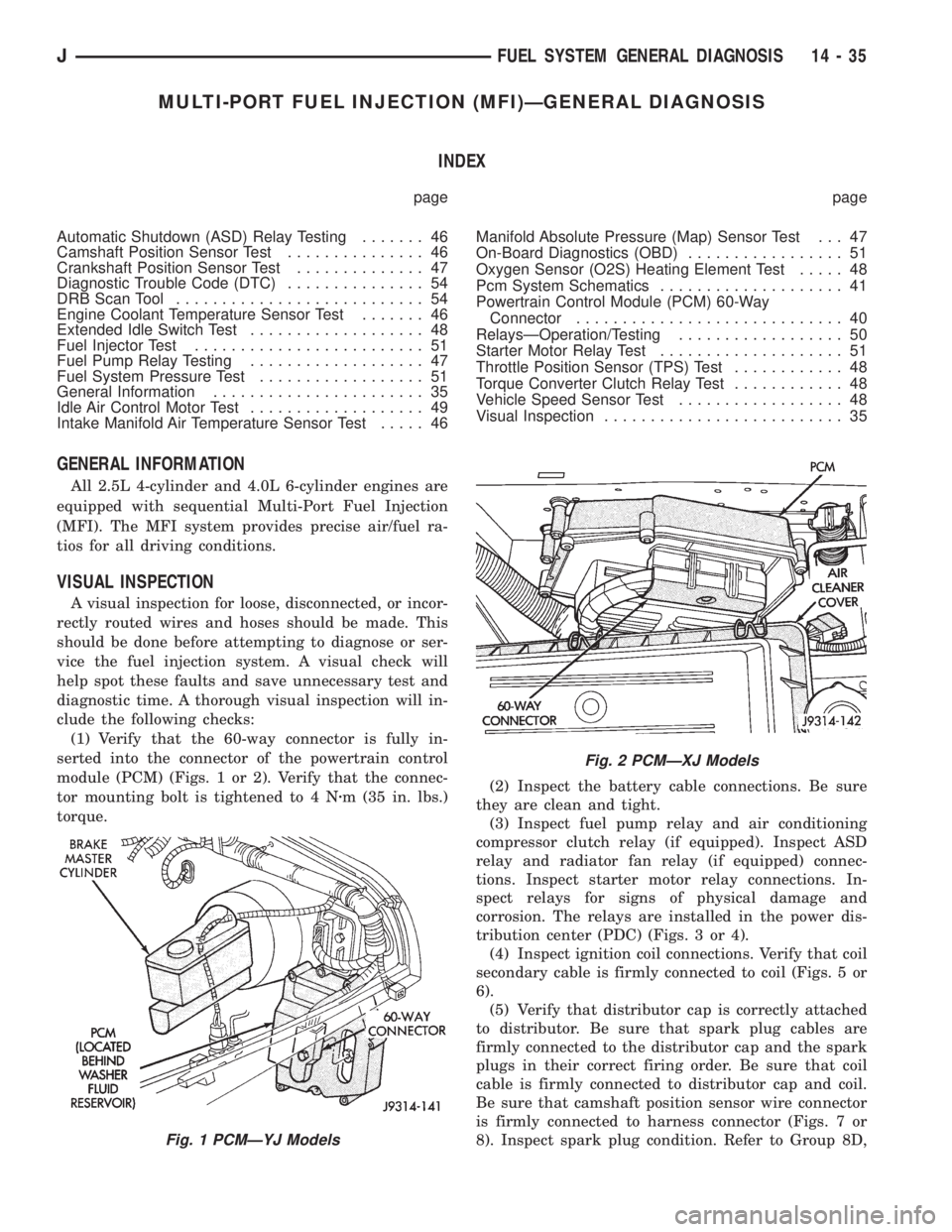
(1) Verify that the 60-way connector is fully in-
serted into the connector of the powertrain control
module (PCM) (Figs. 1 or 2). Verify that the connec-
tor mounting bolt is tightened to 4 Nzm (35 in. lbs.)
torque.(2) Inspect the battery cable connections. Be sure
they are clean and tight.
(3) Inspect fuel pump relay and air conditioning
compressor clutch relay (if equipped). Inspect ASD
relay and radiator fan relay (if equipped) connec-
tions. Inspect starter motor relay connections. In-
spect relays for signs of physical damage and
corrosion. The relays are installed in the power dis-
tribution center (PDC) (Figs. 3 or 4).
(4) Inspect ignition coil connections. Verify that coil
secondary cable is firmly connected to coil (Figs. 5 or
6).
(5) Verify that distributor cap is correctly attached
to distributor. Be sure that spark plug cables are
firmly connected to the distributor cap and the spark
plugs in their correct firing order. Be sure that coil
cable is firmly connected to distributor cap and coil.
Be sure that camshaft position sensor wire connector
is firmly connected to harness connector (Figs. 7 or
8). Inspect spark plug condition. Refer to Group 8D,
Fig. 1 PCMÐYJ Models
Fig. 2 PCMÐXJ Models
JFUEL SYSTEM GENERAL DIAGNOSIS 14 - 35
Page 1254 of 2198
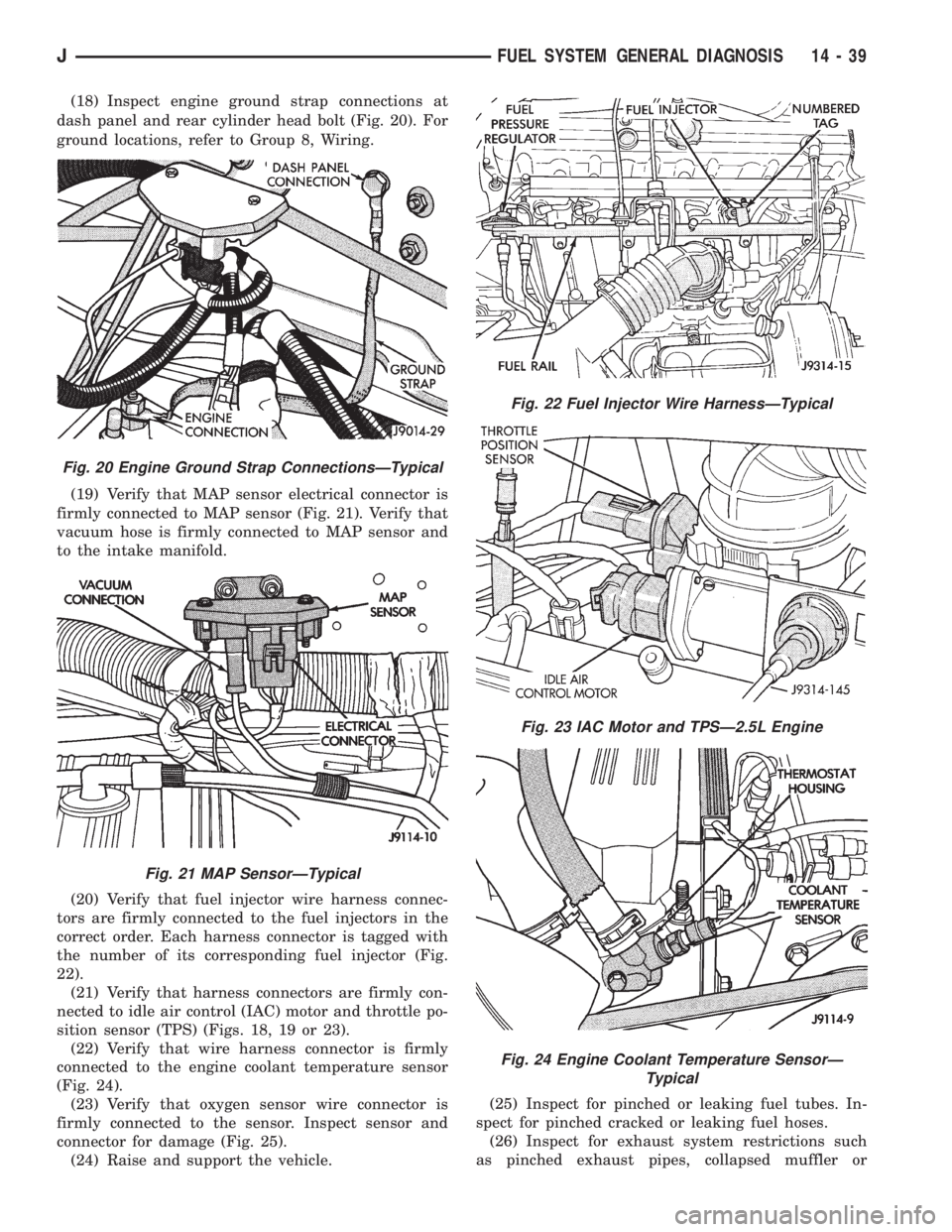
(18) Inspect engine ground strap connections at
dash panel and rear cylinder head bolt (Fig. 20). For
ground locations, refer to Group 8, Wiring.
(19) Verify that MAP sensor electrical connector is
firmly connected to MAP sensor (Fig. 21). Verify that
vacuum hose is firmly connected to MAP sensor and
to the intake manifold.
(20) Verify that fuel injector wire harness connec-
tors are firmly connected to the fuel injectors in the
correct order. Each harness connector is tagged with
the number of its corresponding fuel injector (Fig.
22).
(21) Verify that harness connectors are firmly con-
nected to idle air control (IAC) motor and throttle po-
sition sensor (TPS) (Figs. 18, 19 or 23).
(22) Verify that wire harness connector is firmly
connected to the engine coolant temperature sensor
(Fig. 24).
(23) Verify that oxygen sensor wire connector is
firmly connected to the sensor. Inspect sensor and
connector for damage (Fig. 25).
(24) Raise and support the vehicle.(25) Inspect for pinched or leaking fuel tubes. In-
spect for pinched cracked or leaking fuel hoses.
(26) Inspect for exhaust system restrictions such
as pinched exhaust pipes, collapsed muffler or
Fig. 20 Engine Ground Strap ConnectionsÐTypical
Fig. 21 MAP SensorÐTypical
Fig. 22 Fuel Injector Wire HarnessÐTypical
Fig. 23 IAC Motor and TPSÐ2.5L Engine
Fig. 24 Engine Coolant Temperature SensorÐ
Typical
JFUEL SYSTEM GENERAL DIAGNOSIS 14 - 39
Page 1261 of 2198
AUTOMATIC SHUTDOWN (ASD) RELAY TESTING
To perform a complete test of the ASD relay and its
circuitry, refer to the DRB scan tool and appropriate
Powertrain Diagnostics Procedures manual. To test
the relay only, refer to RelaysÐOperation/Testing in
this section of the group.
CAMSHAFT POSITION SENSOR TEST
Refer to Group 8D, Ignition Systems, for Camshaft
Position Sensor testing.
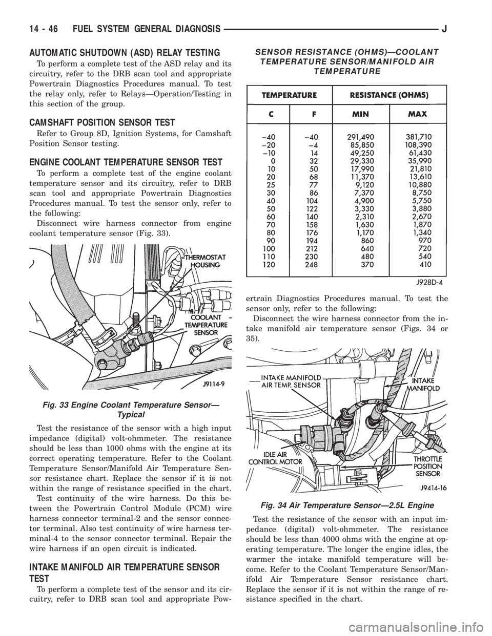
ENGINE COOLANT TEMPERATURE SENSOR TEST
To perform a complete test of the engine coolant
temperature sensor and its circuitry, refer to DRB
scan tool and appropriate Powertrain Diagnostics
Procedures manual. To test the sensor only, refer to
the following:
Disconnect wire harness connector from engine
coolant temperature sensor (Fig. 33).
Test the resistance of the sensor with a high input
impedance (digital) volt-ohmmeter. The resistance
should be less than 1000 ohms with the engine at its
correct operating temperature. Refer to the Coolant
Temperature Sensor/Manifold Air Temperature Sen-
sor resistance chart. Replace the sensor if it is not
within the range of resistance specified in the chart.
Test continuity of the wire harness. Do this be-
tween the Powertrain Control Module (PCM) wire
harness connector terminal-2 and the sensor connec-
tor terminal. Also test continuity of wire harness ter-
minal-4 to the sensor connector terminal. Repair the
wire harness if an open circuit is indicated.
INTAKE MANIFOLD AIR TEMPERATURE SENSOR
TEST
To perform a complete test of the sensor and its cir-
cuitry, refer to DRB scan tool and appropriate Pow-ertrain Diagnostics Procedures manual. To test the
sensor only, refer to the following:
Disconnect the wire harness connector from the in-
take manifold air temperature sensor (Figs. 34 or
35).
Test the resistance of the sensor with an input im-
pedance (digital) volt-ohmmeter. The resistance
should be less than 4000 ohms with the engine at op-
erating temperature. The longer the engine idles, the
warmer the intake manifold temperature will be-
come. Refer to the Coolant Temperature Sensor/Man-
ifold Air Temperature Sensor resistance chart.
Replace the sensor if it is not within the range of re-
sistance specified in the chart.
Fig. 33 Engine Coolant Temperature SensorÐ
Typical
SENSOR RESISTANCE (OHMS)ÐCOOLANT
TEMPERATURE SENSOR/MANIFOLD AIR
TEMPERATURE
Fig. 34 Air Temperature SensorÐ2.5L Engine
14 - 46 FUEL SYSTEM GENERAL DIAGNOSISJ
Page 1270 of 2198
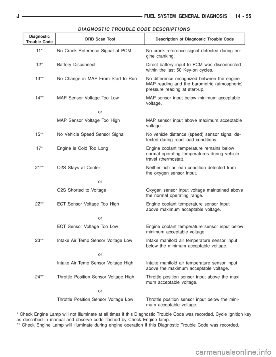
DIAGNOSTIC TROUBLE CODE DESCRIPTIONS
Diagnostic
Trouble CodeDRB Scan Tool Description of Diagnostic Trouble Code
11* No Crank Reference Signal at PCM No crank reference signal detected during en-
gine cranking.
12* Battery Disconnect Direct battery input to PCM was disconnected
within the last 50 Key-on cycles.
13** No Change in MAP From Start to Run No difference recognized between the engine
MAP reading and the barometric (atmospheric)
pressure reading at start-up.
14** MAP Sensor Voltage Too Low MAP sensor input below minimum acceptable
voltage.
or
MAP Sensor Voltage Too High MAP sensor input above maximum acceptable
voltage.
15** No Vehicle Speed Sensor Signal No vehicle distance (speed) sensor signal de-
tected during road load conditions.
17* Engine is Cold Too Long Engine coolant temperature remains below
normal operating temperatures during vehicle
travel (thermostat).
21** O2S Stays at Center Neither rich or lean condition detected from
the oxygen sensor input.
or
O2S Shorted to Voltage Oxygen sensor input voltage maintained above
the normal operating range.
22** ECT Sensor Voltage Too High Engine coolant temperature sensor input
above maximum acceptable voltage.
or
ECT Sensor Voltage Too Low Engine coolant temperature sensor input below
minimum acceptable voltage.
23** Intake Air Temp Sensor Voltage Low Intake manifold air temperature sensor input
below the minimum acceptable voltage.
or
Intake Air Temp Sensor Voltage High Intake manifold air temperature sensor input
above the maximum acceptable voltage.
24** Throttle Position Sensor Voltage High Throttle position sensor input above the maxi-
mum acceptable voltage.
or
Throttle Position Sensor Voltage Low Throttle position sensor input below the mini-
mum acceptable voltage.
* Check Engine Lamp will not illuminate at all times if this Diagnostic Trouble Code was recorded. Cycle Ignition key
as described in manual and observe code flashed by Check Engine lamp.
** Check Engine Lamp will illuminate during engine operation if this Diagnostic Trouble Code was recorded.
JFUEL SYSTEM GENERAL DIAGNOSIS 14 - 55
Page 1272 of 2198
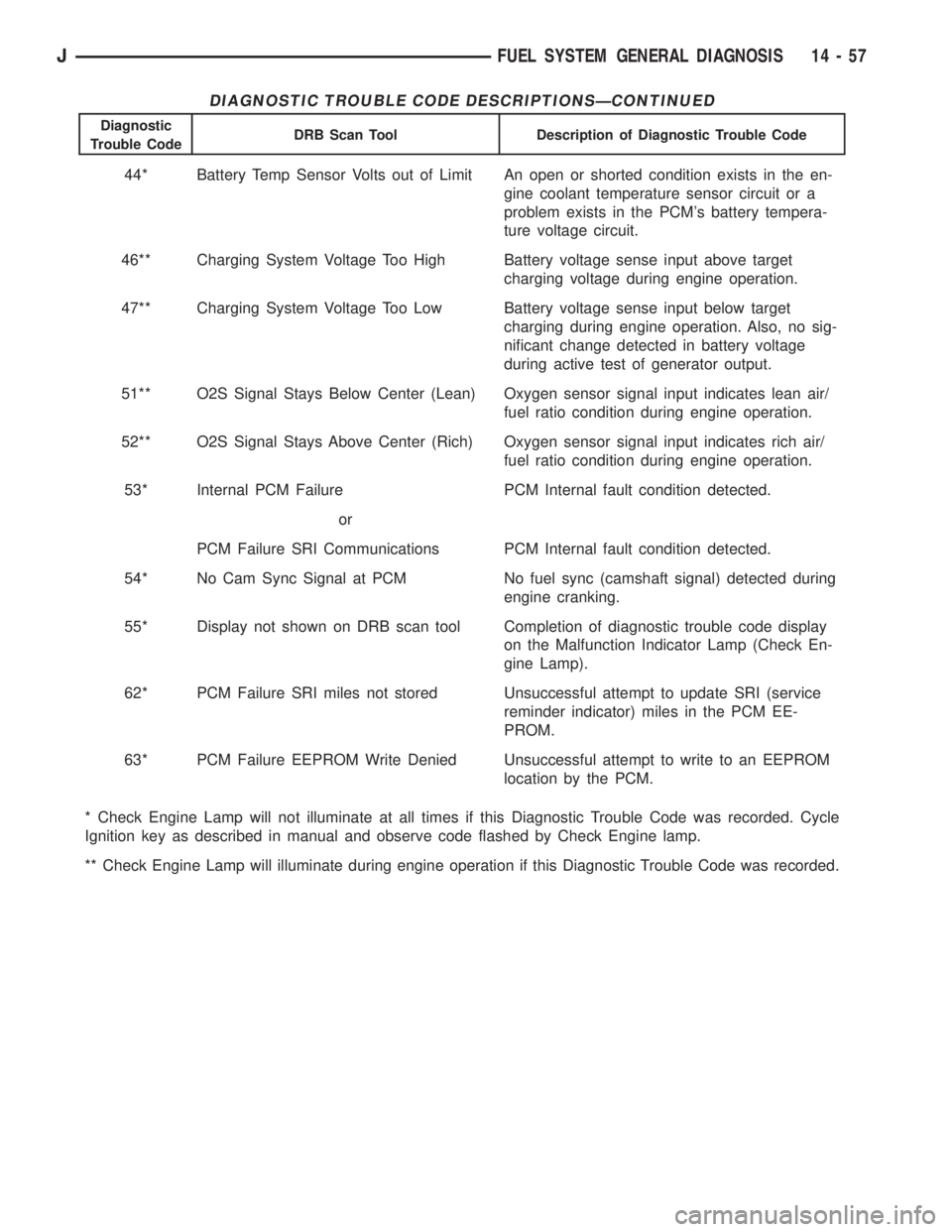
DIAGNOSTIC TROUBLE CODE DESCRIPTIONSÐCONTINUED
Diagnostic
Trouble CodeDRB Scan Tool Description of Diagnostic Trouble Code
44* Battery Temp Sensor Volts out of Limit An open or shorted condition exists in the en-
gine coolant temperature sensor circuit or a
problem exists in the PCM's battery tempera-
ture voltage circuit.
46** Charging System Voltage Too High Battery voltage sense input above target
charging voltage during engine operation.
47** Charging System Voltage Too Low Battery voltage sense input below target
charging during engine operation. Also, no sig-
nificant change detected in battery voltage
during active test of generator output.
51** O2S Signal Stays Below Center (Lean) Oxygen sensor signal input indicates lean air/
fuel ratio condition during engine operation.
52** O2S Signal Stays Above Center (Rich) Oxygen sensor signal input indicates rich air/
fuel ratio condition during engine operation.
53* Internal PCM Failure PCM Internal fault condition detected.
or
PCM Failure SRI Communications PCM Internal fault condition detected.
54* No Cam Sync Signal at PCM No fuel sync (camshaft signal) detected during
engine cranking.
55* Display not shown on DRB scan tool Completion of diagnostic trouble code display
on the Malfunction Indicator Lamp (Check En-
gine Lamp).
62* PCM Failure SRI miles not stored Unsuccessful attempt to update SRI (service
reminder indicator) miles in the PCM EE-
PROM.
63* PCM Failure EEPROM Write Denied Unsuccessful attempt to write to an EEPROM
location by the PCM.
* Check Engine Lamp will not illuminate at all times if this Diagnostic Trouble Code was recorded. Cycle
Ignition key as described in manual and observe code flashed by Check Engine lamp.
** Check Engine Lamp will illuminate during engine operation if this Diagnostic Trouble Code was recorded.
JFUEL SYSTEM GENERAL DIAGNOSIS 14 - 57
Page 1273 of 2198
MULTI-PORT FUEL INJECTION (MFI)ÐCOMPONENT REMOVAL/INSTALLATION
INDEX
page page
Accelerator Pedal and Throttle Cable........... 58
Air Cleaner Element....................... 59
Air Cleaner Housing....................... 58
Air Conditioning (A/C) Clutch Relay............ 58
Automatic Shutdown (ASD) Relay............. 59
Brake Switch............................ 59
Camshaft Position Sensor................... 60
Crankshaft Position Sensor.................. 60
Engine Coolant Temperature Sensor........... 60
Fuel Filter............................... 60
Fuel Injector............................. 60
Fuel Pressure Regulator.................... 61
Fuel Pump Module........................ 61
Fuel Pump Relay......................... 61
Fuel Rail Assembly........................ 62
Fuel System Pressure Release Procedure....... 62
Fuel Tank Pressure Relief/Rollover Valve........ 62Fuel Tanks.............................. 62
Fuel Tubes/Lines/Hoses and Clamps........... 62
Idle Air Control (IAC) Motor.................. 62
Ignition Coil............................. 62
Intake Manifold........................... 63
Intake Manifold Air Temperature Sensor......... 60
Manifold Absolute Pressure (Map) Sensor....... 63
Oxygen (O2S) Sensor...................... 63
Park Neutral Switch....................... 63
Power Steering Pressure SwitchÐ2.5L
Engine Only............................ 63
Powertrain Control Module (PCM)............. 64
Quick-Connect Fittings..................... 64
Throttle Body............................ 64
Throttle Position Sensor (TPS)............... 65
Torque Converter Clutch Relay............... 65
Vehicle Speed Sensor...................... 66
ACCELERATOR PEDAL AND THROTTLE CABLE
Refer to the Accelerator Pedal and Throttle Cable
section of this group for removal/installation proce-
dures.
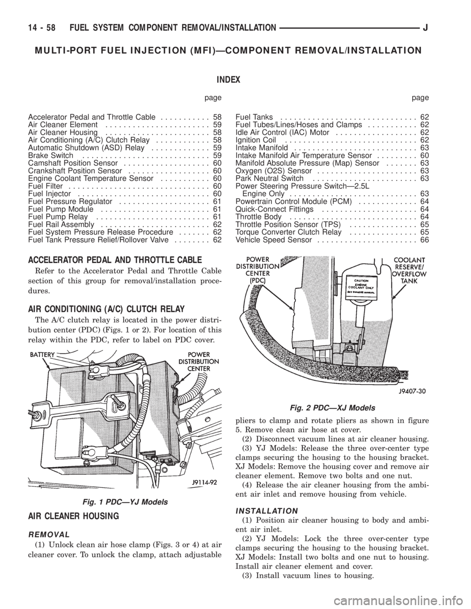
AIR CONDITIONING (A/C) CLUTCH RELAY
The A/C clutch relay is located in the power distri-
bution center (PDC) (Figs. 1 or 2). For location of this
relay within the PDC, refer to label on PDC cover.
AIR CLEANER HOUSING
REMOVAL
(1) Unlock clean air hose clamp (Figs. 3 or 4) at air
cleaner cover. To unlock the clamp, attach adjustablepliers to clamp and rotate pliers as shown in figure
5. Remove clean air hose at cover.
(2) Disconnect vacuum lines at air cleaner housing.
(3) YJ Models: Release the three over-center type
clamps securing the housing to the housing bracket.
XJ Models: Remove the housing cover and remove air
cleaner element. Remove two bolts and one nut.
(4) Release the air cleaner housing from the ambi-
ent air inlet and remove housing from vehicle.
INSTALLATION
(1) Position air cleaner housing to body and ambi-
ent air inlet.
(2) YJ Models: Lock the three over-center type
clamps securing the housing to the housing bracket.
XJ Models: Install two bolts and one nut to housing.
Install air cleaner element and cover.
(3) Install vacuum lines to housing.
Fig. 1 PDCÐYJ Models
Fig. 2 PDCÐXJ Models
14 - 58 FUEL SYSTEM COMPONENT REMOVAL/INSTALLATIONJ