Page 1275 of 2198
CAMSHAFT POSITION SENSOR
For removal/installation procedures, refer to Group
8D, Ignition System. See Camshaft Position Sensor.
INTAKE MANIFOLD AIR TEMPERATURE SENSOR
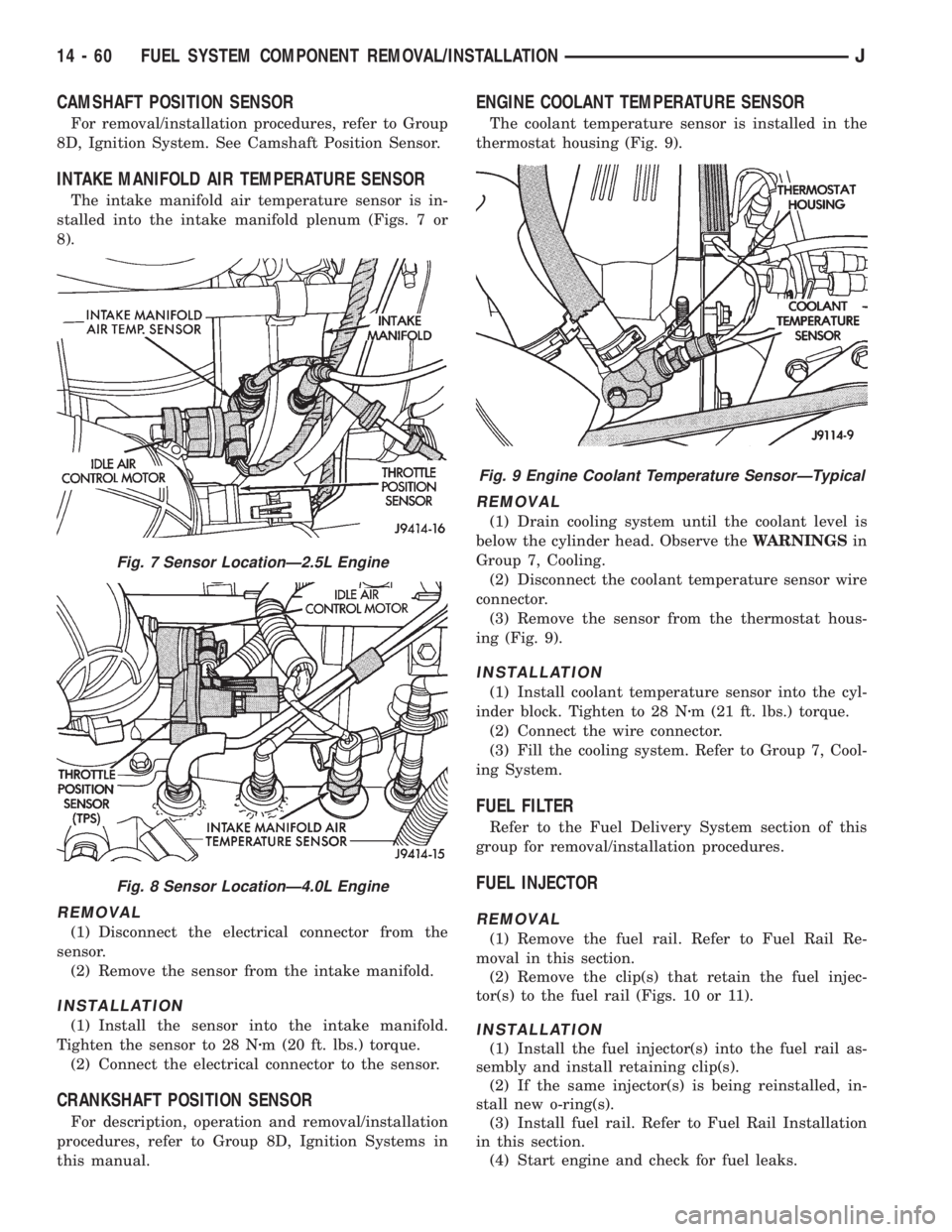
The intake manifold air temperature sensor is in-
stalled into the intake manifold plenum (Figs. 7 or
8).
REMOVAL
(1) Disconnect the electrical connector from the
sensor.
(2) Remove the sensor from the intake manifold.
INSTALLATION
(1) Install the sensor into the intake manifold.
Tighten the sensor to 28 Nzm (20 ft. lbs.) torque.
(2) Connect the electrical connector to the sensor.
CRANKSHAFT POSITION SENSOR
For description, operation and removal/installation
procedures, refer to Group 8D, Ignition Systems in
this manual.
ENGINE COOLANT TEMPERATURE SENSOR
The coolant temperature sensor is installed in the
thermostat housing (Fig. 9).
REMOVAL
(1) Drain cooling system until the coolant level is
below the cylinder head. Observe theWARNINGSin
Group 7, Cooling.
(2) Disconnect the coolant temperature sensor wire
connector.
(3) Remove the sensor from the thermostat hous-
ing (Fig. 9).
INSTALLATION
(1) Install coolant temperature sensor into the cyl-
inder block. Tighten to 28 Nzm (21 ft. lbs.) torque.
(2) Connect the wire connector.
(3) Fill the cooling system. Refer to Group 7, Cool-
ing System.
FUEL FILTER
Refer to the Fuel Delivery System section of this
group for removal/installation procedures.
FUEL INJECTOR
REMOVAL
(1) Remove the fuel rail. Refer to Fuel Rail Re-
moval in this section.
(2) Remove the clip(s) that retain the fuel injec-
tor(s) to the fuel rail (Figs. 10 or 11).
INSTALLATION
(1) Install the fuel injector(s) into the fuel rail as-
sembly and install retaining clip(s).
(2) If the same injector(s) is being reinstalled, in-
stall new o-ring(s).
(3) Install fuel rail. Refer to Fuel Rail Installation
in this section.
(4) Start engine and check for fuel leaks.
Fig. 7 Sensor LocationÐ2.5L Engine
Fig. 8 Sensor LocationÐ4.0L Engine
Fig. 9 Engine Coolant Temperature SensorÐTypical
14 - 60 FUEL SYSTEM COMPONENT REMOVAL/INSTALLATIONJ
Page 1748 of 2198
²Front fender.
REMOVAL
(1) Remove the front bumper.
(2) Right fender only:
²If equipped, remove the radio antenna mast, and
components from the fender (Fig. 34 and 35).
²Remove the battery and tray from the fender inner
panel (Fig. 36, 37 and 38).
Fig. 36 Battery, Speed Servo, PDC & Coolant
Recovery Bottle
Fig. 37 Battery Removal/Installation
Fig. 38 Battery Tray Removal/Installation
Fig. 34 Radio Antenna Removal/Installation
Fig. 35 Power Antenna Wire Harness & Cable
Connectors
JEXTERIOR COMPONENTSÐXJ 23 - 15
Page 1749 of 2198
²Remove windshield washer reservoir from fender
inner panel (Fig. 39).
²Remove the hood ajar switch, if equipped, from
fender (Fig. 40 and 41).
²Remove the Power Distribution Center (PDC), the
coolant recovery bottle and speed servo from fender
the inner panel (Fig. 42, 43 and 44).
Fig. 41 Hood Ajar Switch Removal/Installation
Fig. 42 Power Distribution Center and Vapor
Canister
Fig. 43 Coolant Recovery Bottle
Fig. 39 Coolant Recovery Bottle, Windshield Washer
Fluid Reservoir & Hood Support Rod
Fig. 40 Hood Ajar Switch, Speed Servo & A/C
Receiver/Drier
23 - 16 EXTERIOR COMPONENTSÐXJJ
Page 1752 of 2198
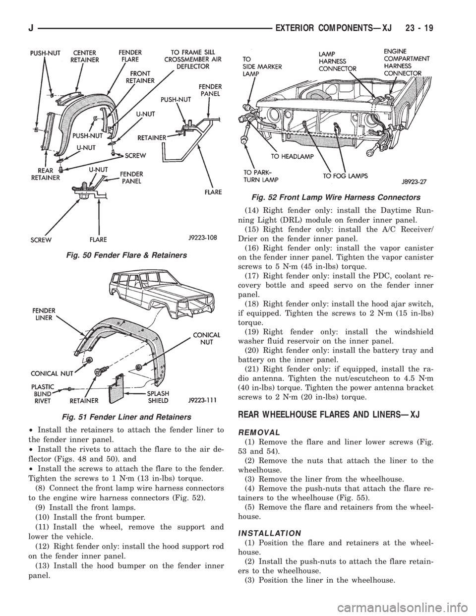
²Install the retainers to attach the fender liner to
the fender inner panel.
²Install the rivets to attach the flare to the air de-
flector (Figs. 48 and 50). and
²Install the screws to attach the flare to the fender.
Tighten the screws to 1 Nzm (13 in-lbs) torque.
(8) Connect the front lamp wire harness connectors
to the engine wire harness connectors (Fig. 52).
(9) Install the front lamps.
(10) Install the front bumper.
(11) Install the wheel, remove the support and
lower the vehicle.
(12) Right fender only: install the hood support rod
on the fender inner panel.
(13) Install the hood bumper on the fender inner
panel.(14) Right fender only: install the Daytime Run-
ning Light (DRL) module on fender inner panel.
(15) Right fender only: install the A/C Receiver/
Drier on the fender inner panel.
(16) Right fender only: install the vapor canister
on the fender inner panel. Tighten the vapor canister
screws to 5 Nzm (45 in-lbs) torque.
(17) Right fender only: install the PDC, coolant re-
covery bottle and speed servo on the fender inner
panel.
(18) Right fender only: install the hood ajar switch,
if equipped. Tighten the screws to 2 Nzm (15 in-lbs)
torque.
(19) Right fender only: install the windshield
washer fluid reservoir on the inner panel.
(20) Right fender only: install the battery tray and
battery on the inner panel.
(21) Right fender only: if equipped, install the ra-
dio antenna. Tighten the nut/escutcheon to 4.5 Nzm
(40 in-lbs) torque. Tighten the power antenna bracket
screws to 2 Nzm (20 in-lbs) torque.
REAR WHEELHOUSE FLARES AND LINERSÐXJ
REMOVAL
(1) Remove the flare and liner lower screws (Fig.
53 and 54).
(2) Remove the nuts that attach the liner to the
wheelhouse.
(3) Remove the liner from the wheelhouse.
(4) Remove the push-nuts that attach the flare re-
tainers to the wheelhouse (Fig. 55).
(5) Remove the flare and retainers from the wheel-
house.
INSTALLATION
(1) Position the flare and retainers at the wheel-
house.
(2) Install the push-nuts to attach the flare retain-
ers to the wheelhouse.
(3) Position the liner in the wheelhouse.
Fig. 50 Fender Flare & Retainers
Fig. 51 Fender Liner and Retainers
Fig. 52 Front Lamp Wire Harness Connectors
JEXTERIOR COMPONENTSÐXJ 23 - 19
Page 1845 of 2198
²Remove the horn from the fender inner panel (Fig.
7).
²Remove the windshield washer fluid reservoir and
coolant reserve bottle from the fender inner panel
(Fig. 8 and 9).(4) Right fender:
²Remove the jack and related tools from the jack
storage tray (Fig. 10).
²Remove the jack storage tray and A/C receiver/
drier from the fender inner panel (Fig. 11).
Fig. 7 Horn Removal/Installation
Fig. 8 Windshield Washer Fluid Reservoir
Fig. 9 Coolant Reserve Bottle
Fig. 10 Jack and Related Tools
Fig. 11 Jack Storage Tray and A/C Receiver/Drier
23 - 112 EXTERIOR COMPONENTSÐYJJ
Page 1847 of 2198
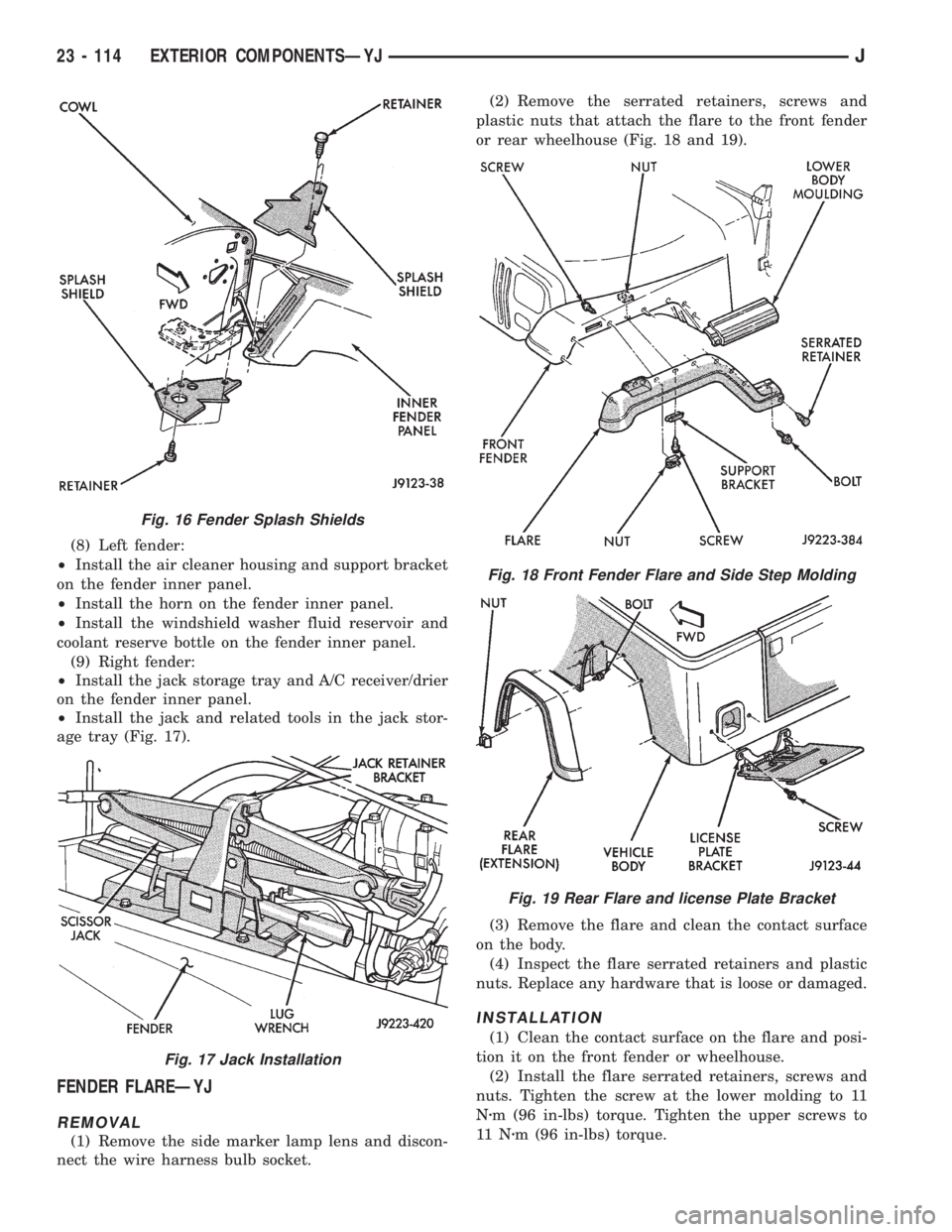
(8) Left fender:
²Install the air cleaner housing and support bracket
on the fender inner panel.
²Install the horn on the fender inner panel.
²Install the windshield washer fluid reservoir and
coolant reserve bottle on the fender inner panel.
(9) Right fender:
²Install the jack storage tray and A/C receiver/drier
on the fender inner panel.
²Install the jack and related tools in the jack stor-
age tray (Fig. 17).
FENDER FLAREÐYJ
REMOVAL
(1) Remove the side marker lamp lens and discon-
nect the wire harness bulb socket.(2) Remove the serrated retainers, screws and
plastic nuts that attach the flare to the front fender
or rear wheelhouse (Fig. 18 and 19).
(3) Remove the flare and clean the contact surface
on the body.
(4) Inspect the flare serrated retainers and plastic
nuts. Replace any hardware that is loose or damaged.
INSTALLATION
(1) Clean the contact surface on the flare and posi-
tion it on the front fender or wheelhouse.
(2) Install the flare serrated retainers, screws and
nuts. Tighten the screw at the lower molding to 11
Nzm (96 in-lbs) torque. Tighten the upper screws to
11 Nzm (96 in-lbs) torque.
Fig. 16 Fender Splash Shields
Fig. 17 Jack Installation
Fig. 18 Front Fender Flare and Side Step Molding
Fig. 19 Rear Flare and license Plate Bracket
23 - 114 EXTERIOR COMPONENTSÐYJJ
Page 1896 of 2198
HEATING AND AIR CONDITIONING
CONTENTS
page page
COMPONENT SERVICEÐXJ VEHICLES...... 23
COMPONENT SERVICEÐYJ VEHICLES...... 32
COMPRESSOR SERVICE.................. 19
GENERAL INFORMATION.................. 1
HEATING AND AIR CONDITIONING TEST
PROCEDURES......................... 15REFRIGERANT SERVICE AND PERFORMANCE
TEST................................ 11
TORQUE SPECIFICATIONS................ 37
WARNINGS, CAUTIONS AND SERVICE
PRECAUTIONS......................... 9
GENERAL INFORMATION
INDEX
page page
A/C Components.......................... 4
Heater and A/C Operation.................... 1
Manifold Gauge Set........................ 7Refrigerant............................... 7
Refrigerant Equipment...................... 7
HEATER AND A/C OPERATION
HEATERÐXJ
A blend-air heating system is used in XJ vehicles.
The temperature of heated air is controlled by regu-
lating the quantity of air flow through the heater
core. This is accomplished by blending outside air
with heated air from the heater core to obtain the de-
sired discharge temperature. A temperature control
lever on the heater control determines air flow
through the heater core. The lever uses a cable to op-erate the blend-air door. This door controls air flow
through the core. Vacuum motors are used to actuate
and position the remaining door in the system.
On left hand drive (LHD) XJ vehicles a water valve
controls coolant flow to the heater core. The valve is
vacuum operated. When vacuum is applied, the valve
opens and coolant is directed through the heater core
and back to the engine. When the water valve is
closed (no vacuum applied) coolant flow bypasses the
heater core back to the engine.
JHEATING AND AIR CONDITIONING 24 - 1
Page 1898 of 2198
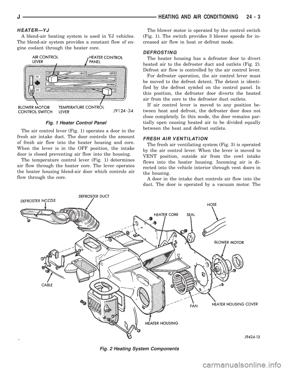
HEATERÐYJ
A blend-air heating system is used in YJ vehicles.
The blend-air system provides a constant flow of en-
gine coolant through the heater core.
The air control lever (Fig. 1) operates a door in the
fresh air intake duct. The door controls the amount
of fresh air flow into the heater housing and core.
When the lever is in the OFF position, the intake
door is closed preventing air flow into the housing.
The temperature control lever (Fig. 1) determines
air flow through the heater core. The lever operates
the heater housing blend-air door which controls air
flow through the core.The blower motor is operated by the control switch
(Fig. 1). The switch provides 3 blower speeds for in-
creased air flow in heat or defrost mode.
DEFROSTING
The heater housing has a defroster door to divert
heated air to the defroster duct and outlets (Fig. 2).
Defrost air flow is controlled by the air control lever.
For defroster operation, the air control lever must
be moved to the defrost detent. The detent is identi-
fied by the defrost symbol on the control panel. In
this position, the defroster door diverts the heated
air from the core to the defroster duct outlets.
If air control lever is moved to any position be-
tween heat and defrost, the defroster door does not
close completely. In this mode, the door remains par-
tially open causing heated air to be divided equally
between the heat and defrost outlets.
FRESH AIR VENTILATION
The fresh air ventilating system (Fig. 3) is operated
by the air control lever. When the lever is moved to
VENT position, outside air from the cowl intake
flows into the heater housing. Incoming air is di-
rected into the vehicle interior through vent doors in
the housing.
A door in the intake duct controls air flow into the
duct. The door is operated by a vacuum motor. The
Fig. 2 Heating System Components
Fig. 1 Heater Control Panel
JHEATING AND AIR CONDITIONING 24 - 3