Page 1300 of 1771
Kickback and Pump Operation:
When the engine is started, the ABS control unit begins the initial diagnosis and operates the solenoid valve one time.
The kickback may be felt when the brake pedal is depressed.
When the ABS control unit detects the pressure switch OFF signal during the initial diagnosis, it operates the pump
motor, and performs the pump motor over-run diagnosis and pump motor diagnosis. Therefore, there are two cases
where the pump motor operates or does not operate after the engine is started.
Normally, after the initial diagnosis, the pump motor operates based on the pressure switch signal, regardless of the
vehicle speed.
Troubleshooting:
When two or three DTCs are stored in the control unit, perform troubleshooting for the DTC that appears first.
When a customer's reported problem cannot be verified on the car, ask the customer about the conditions when the
ABS indicator light came ON, and test-drive the car under those conditions, if possible. When the ABS indicator light
does not come ON during the test, check for loose terminals and check by shaking the harnesses and connectors while
following the flowchart.
The connector terminal numbers are viewed from the wire side for the female terminals, and from the terminal side for
the male terminals.
After the repair is completed, test-drive the car and check that the ABS indicator light does not come ON again during
the test. (Refer to the Symptom-to-System Chart for diagnostic period.)ProCarManuals.com
Page 1302 of 1771
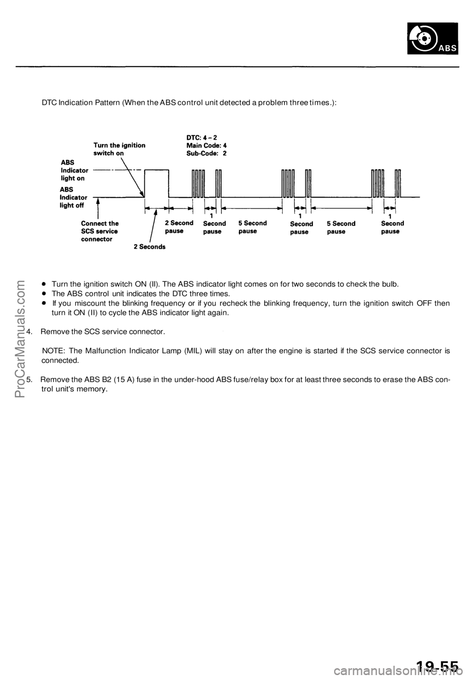
DTC Indication Pattern (When the ABS control unit detected a problem three times.):
Turn the ignition switch ON (II). The ABS indicator light comes on for two seconds to check the bulb.
The ABS control unit indicates the DTC three times.
If you miscount the blinking frequency or if you recheck the blinking frequency, turn the ignition switch OFF then
turn it ON (II) to cycle the ABS indicator light again.
4. Remove the SCS service connector.
NOTE: The Malfunction Indicator Lamp (MIL) will stay on after the engine is started if the SCS service connector is
connected.
5. Remove the ABS B2 (15 A) fuse in the under-hood ABS fuse/relay box for at least three seconds to erase the ABS con-
trol unit's memory.ProCarManuals.com
Page 1335 of 1771
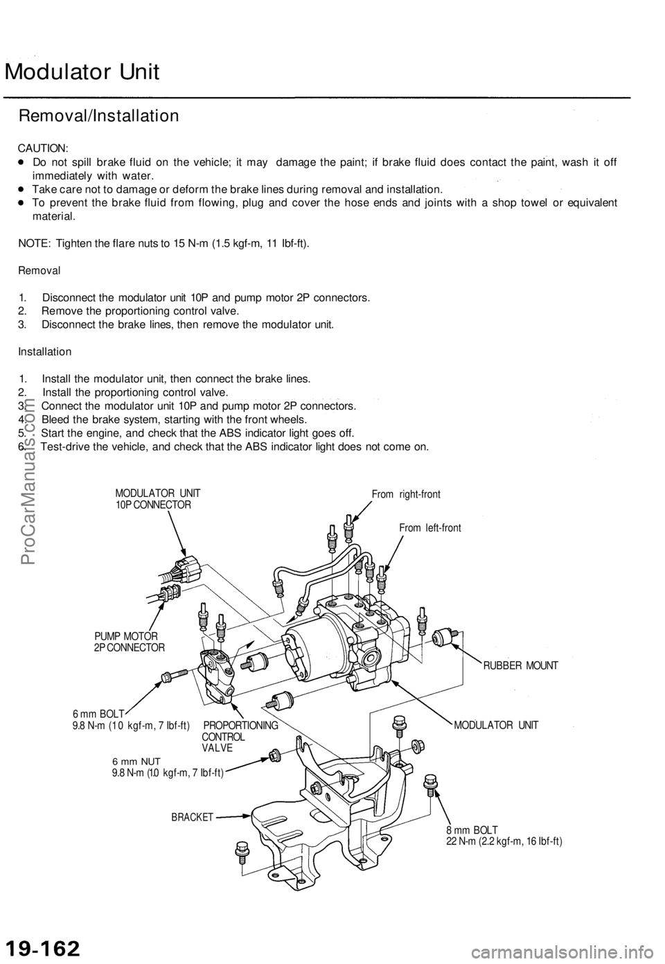
Modulator Unit
Removal/Installation
CAUTION:
Do not spill brake fluid on the vehicle; it may damage the paint; if brake fluid does contact the paint, wash it off
immediately with water.
Take care not to damage or deform the brake lines during removal and installation.
To prevent the brake fluid from flowing, plug and cover the hose ends and joints with a shop towel or equivalent
material.
NOTE: Tighten the flare nuts to 15 N-m (1.5 kgf-m, 11 Ibf-ft).
Removal
1. Disconnect the modulator unit 10P and pump motor 2P connectors.
2. Remove the proportioning control valve.
3. Disconnect the brake lines, then remove the modulator unit.
Installation
1. Install the modulator unit, then connect the brake lines.
2. Install the proportioning control valve.
3. Connect the modulator unit 10P and pump motor 2P connectors.
4. Bleed the brake system, starting with the front wheels.
5. Start the engine, and check that the ABS indicator light goes off.
6. Test-drive the vehicle, and check that the ABS indicator light does not come on.
MODULATOR UNIT
10P CONNECTOR
From right-front
From left-front
PUMP MOTOR
2P CONNECTOR
6 mm BOLT
9.8 N-m (1 .0 kgf-m, 7 Ibf-ft) PROPORTIONING
CONTROL
VALVE
6 mm NUT
9.8 N-m (1.0 kgf-m, 7 Ibf-ft)
BRACKET
RUBBER MOUNT
MODULATOR UNIT
8 mm BOLT
22 N-m (2.2 kgf-m, 16 Ibf-ft)ProCarManuals.com
Page 1580 of 1771
(From page 23-96 )
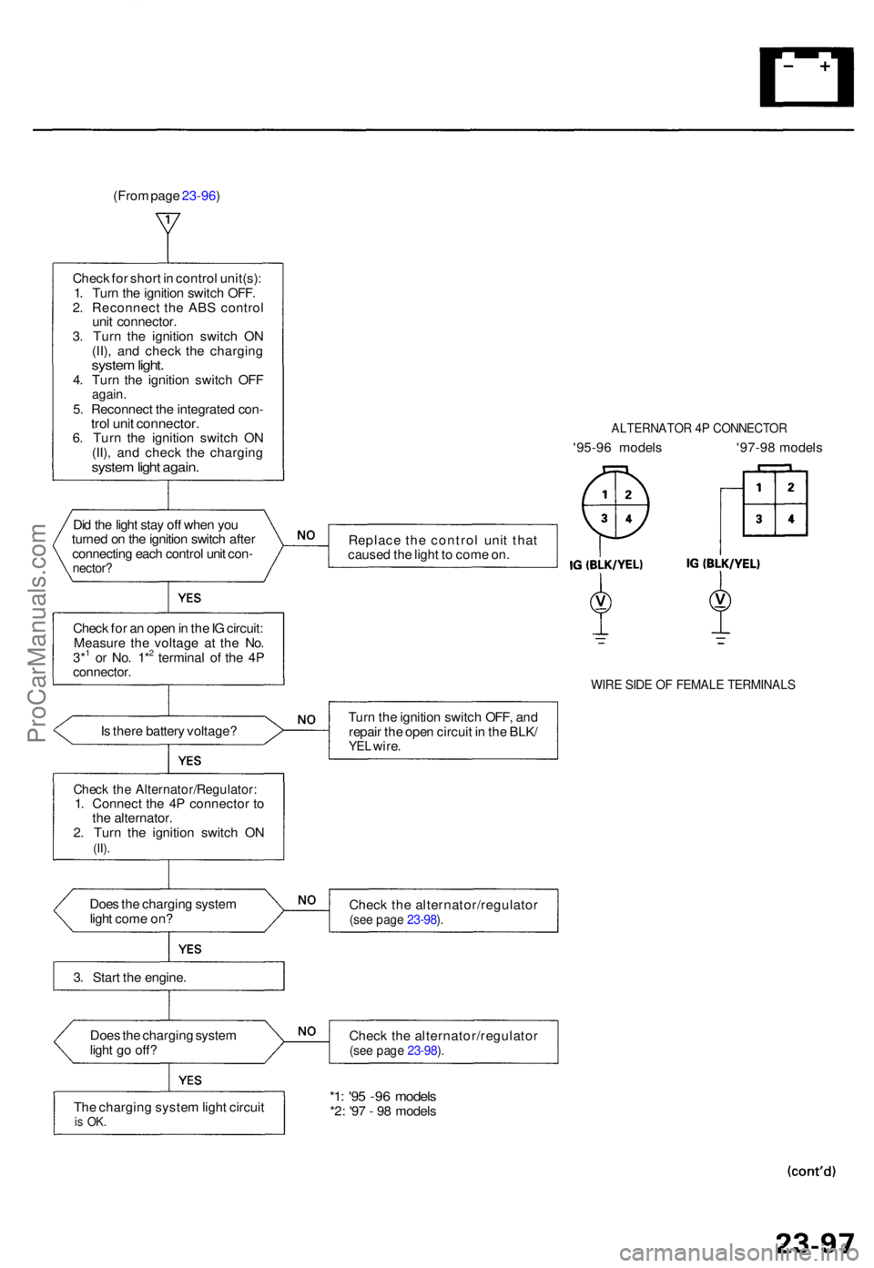
Chec k fo r shor t i n contro l unit(s) :
1 . Tur n th e ignitio n switc h OFF .
2 . Reconnec t th e AB S contro l
uni t connector .
3 . Tur n th e ignitio n switc h O N
(II) , an d chec k th e chargin g
system light .4. Tur n th e ignitio n switc h OF Fagain .5. Reconnec t th e integrate d con -trol uni t connector .6. Tur n th e ignitio n switc h O N
(II) , an d chec k th e chargin g
system ligh t again .
Did th e ligh t sta y of f whe n yo u
turne d o n th e ignitio n switc h afte r
connectin g eac h contro l uni t con -
nector ?
Check fo r a n ope n in th e IG circuit :
Measur e th e voltag e a t th e No .
3*
1 o r No . 1*2 termina l o f th e 4 Pconnector .
ALTERNATO R 4 P CONNECTO R
'95-96 model s '97-9 8 model s
Replac e th e contro l uni t tha t
cause d th e ligh t t o com e on .
WIR E SID E O F FEMAL E TERMINAL S
Is ther e batter y voltage ? Tur
n th e ignitio n switc h OFF , an d
repai r th e ope n circui t i n th e BLK /YEL wire .
Chec k th e Alternator/Regulator :1. Connec t th e 4 P connecto r t o
th e alternator .
2 . Tur n th e ignitio n switc h O N
(II).
Doe s th e chargin g syste m
ligh t com e on ? Chec
k th e alternator/regulato r(see pag e 23-98 ).
3 . Star t th e engine .
Doe s th e chargin g syste m
ligh t g o off ? Chec
k th e alternator/regulato r
(see pag e 23-98 ).
Th e chargin g syste m ligh t circui tis OK .
*1: '9 5 -9 6 model s*2: '9 7 - 9 8 model s
ProCarManuals.com