Page 1419 of 1771
Replacement
SRS component s ar e locate d in thi s area . Revie w th e SR S
componen t locations , precautions , an d procedure s i n th e
SR S sectio n 24 befor e preformin g repair s o r service .
NOTE:
• A n assistan t i s helpfu l whe n removin g an d installin g
th e dashboard .
• Tak e car e no t t o scratc h th e dashboard , bod y an d
relate d parts .
1 . Remove :
Dashboar d lowe r cove r (se e pag e 20-65 )
Kne e bolste r (se e pag e 20-65 )
Cente r consol e (se e pag e 20-64 )
Glov e bo x
Kic k panel s (se e pag e 20-63 )
2 . Remov e th e dashboar d cente r trim .
DASHBOAR DCENTER TRI M
3. Mak e sur e yo u hav e th e anti-thef t cod e fo r th e radio ,
the n writ e dow n th e frequencie s fo r th e radio' s prese t
buttons .
Clip location s
ProCarManuals.com
Page 1420 of 1771

Dashboard
Replacemen t (cont'd )
4. Lowe r th e steerin g colum n (se e sectio n 17 ).
T o avoi d accidenta l deploymen t an d possi -
bl e injury , alway s disconnec t th e driver' s airba g connec -
to r befor e lowerin g th e steerin g colum n (se e sectio n 24 ).
NOTE : T o preven t damag e t o th e steerin g column , wra p it
wit h a sho p towel.
10 x 1.2 5 mm38 N- m (3. 9 kgf-m ,
2 8 Ibf-ft )
8 x 1.2 5 mm16 N- m (1. 6 kgf-m ,12 Ibf-ft )Replace .
STEERIN GCOLUMN
STEERIN G JOIN TCOVE RCLAMP S
5. Disconnec t th e dashboar d wir e harnes s connector s
an d harnes s clips .
CLIPSCONNECTO R
DASHBOAR DWIRE HARNES S
DASHBOAR DWIRE HARNES S CONNECTOR
S
CONNECTORS
6. Remov e th e airba g bracket .
T o avoi d accidenta l deploymen t an d
possibl e injury , alway s instal l th e protectiv e shor t
connecto r o n th e fron t passenger' s airba g connec -
to r whe n th e SR S mai n harnes s i s disconnecte d
(se e sectio n 24 ).
6 x 1. 0 m m9.8 N- m(1.0 kgf-m ,
7. 2 Ibf-ft )
AIRBA GBRACKE T
FRONT PASSENGER' SAIRBAG
ProCarManuals.com
Page 1421 of 1771

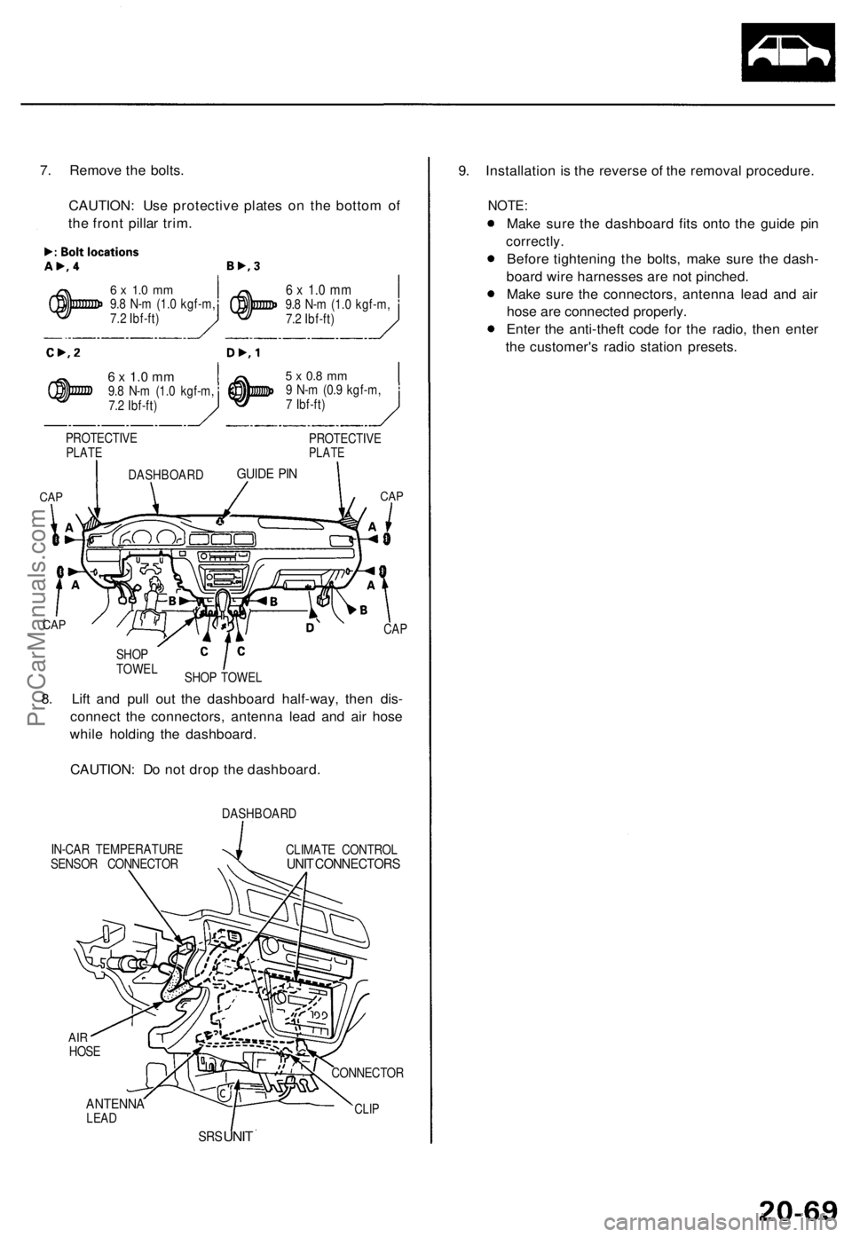
7. Remov e th e bolts .
CAUTION : Us e protectiv e plate s o n th e botto m o f
th e fron t pilla r trim .
6 x 1. 0 m m9.8 N- m (1. 0 kgf-m ,
7. 2 Ibf-ft )
6 x 1. 0 m m9.8 N- m (1. 0 kgf-m ,
7. 2 Ibf-ft )
6 x 1. 0 m m9.8 N- m (1. 0 kgf-m ,
7. 2 Ibf-ft )
PROTECTIV E
PLATE
CAP CA
P
IN-CA R TEMPERATUR E
SENSO R CONNECTO RDASHBOAR
D
CLIMAT E CONTRO LUNIT CONNECTOR S
ANTENNALEAD
SRS UNI T 9
. Installatio n i s th e revers e o f th e remova l procedure .
NOTE:
Make sur e th e dashboar d fit s ont o th e guid e pi n
correctly .
Before tightenin g th e bolts , mak e sur e th e dash -
boar d wir e harnesse s ar e no t pinched .
Mak e sur e th e connectors , antenn a lea d an d ai r
hos e ar e connecte d properly .
Ente r th e anti-thef t cod e fo r th e radio , the n ente r
th e customer' s radi o statio n presets .
CLIP
CONNECTO R
8. Lif t an d pul l ou t th e dashboar d half-way , the n dis -
connec t th e connectors , antenn a lea d an d ai r hos e
whil e holdin g th e dashboard .
CAUTION : D o no t dro p th e dashboard .
CAP
SHO P TOWE L
SHO
P
TOWE L
CAP
DASHBOAR DGUIDE PI N
5 x 0. 8 m m9 N- m (0. 9 kgf-m ,
7 Ibf-ft )
PROTECTIV E
PLATE
AIRHOS E
ProCarManuals.com
Page 1498 of 1771

Climate Contro l Uni t
Replacemen t
Bulb Replacemen t
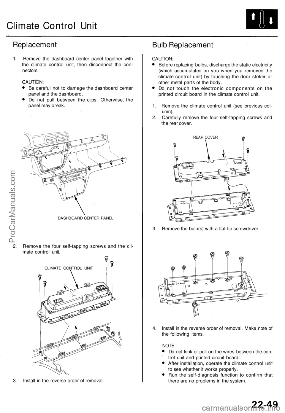
1. Remov e th e dashboar d cente r pane l togethe r wit h
th e climat e contro l unit , the n disconnec t th e con -
nectors .
CAUTION :
B e carefu l no t t o damag e th e dashboar d cente r
pane l an d th e dashboard .
D o no t pul l betwee n th e clips : Otherwise , th e
pane l ma y break .
DASHBOAR D CENTE R PANE L
2. Remov e th e fou r self-tappin g screw s an d th e cli -
mat e contro l unit .
CLIMAT E CONTRO L UNI T
3. Instal l i n th e revers e orde r o f removal . CAUTION
:
Befor e replacin g bulbs , discharg e th e stati c electricit y
(whic h accumulate d o n yo u whe n yo u remove d th e
climat e contro l unit ) b y touchin g th e doo r strike r o r
othe r meta l part s o f th e body .
D o no t touc h th e electroni c component s o n th e
printe d circui t boar d in th e climat e contro l unit .
1 . Remov e th e climat e contro l uni t (se e previou s col -
umn) .
2. Carefull y remov e th e fou r self-tappin g screw s an d
th e rea r cover .
REAR COVE R
3. Remov e th e bulb(s ) wit h a flat-ti p screwdriver .
4 . Instal l i n th e revers e orde r o f removal . Mak e not e o f
th e followin g items .
NOTE:
Do no t kin k o r pul l o n th e wire s betwee n th e con -
tro l uni t an d printe d circui t board .
Afte r installation , operat e th e climat e contro l uni t
t o se e whethe r i t work s properly .
Ru n th e self-diagnosi s functio n t o confir m tha t
ther e ar e n o problem s i n th e system .
ProCarManuals.com
Page 1502 of 1771
In-car Temperatur e Senso r
Replacemen t
1. Remove the dashboard center panel (see page
22-49).
2 . Remov e th e in-ca r temperatur e senso r fro m th e
dashboard , the n disconnec t th e 2 P connecto r an d
th e ai r hose .
AIR HOS E
IN-CA R TEMPERATUR E SENSO R
3. Instal l i n th e revers e orde r o f removal .
NOTE : B e sur e to connec t th e ai r hos e securely .
Test
Compar e th e resistanc e readin g betwee n th e No . 1 an d
No . 2 terminal s o f th e in-ca r temperatur e senso r wit h
th e specification s show n i n followin g graph ; resistanc e
shoul d b e withi n specifications .
NOTE : Chec k fo r chang e i n resistanc e b y heatin g o r
coolin g th e senso r wit h a hai r drier , etc .
CAUTION : Th e senso r use s a thermisto r whic h ca n b e
damage d i f hig h curren t i s applie d durin g testing .
Therefore , us e a circui t teste r wit h a n outpu t o f 1 m A o r
les s a t th e 2 0 k range .
IN-CAR TEMPERATUR E SENSO R
TEMPERATUR E
ProCarManuals.com
Page 1541 of 1771
Dashboard
PGM-FI MAI N RELA Y
CRUIS E CONTRO L UNI T
DAS H LIGHT S
BRIGHTNES S
CONTROLLE R(Has built-i n contro lunit)
TUR N SIGNAL /HAZARD RELA Y
UNDER-DAS H
FUSE/RELA Y BO X INTERLOC
K CONTRO L UNI T
STARTE R CU T RELA YWire colors : BLK/GRN ,BLK/GRN, YEL/GR N an d BLK/WH T
SRS UNI T
INTEGRATE D
CONTRO L UNI TCIGARETT ELIGHTERRELAY
REAR WINDO WDEFOGGE RRELAY
ProCarManuals.com
Page 1542 of 1771
Relay and Control Unit Locations
Dashboard (cont'd)
ABS FAIL-SAFE RELAY
('97-98 models)
ABS FRONT FAIL-SAFE RELAY
('95 - 96 models)
FOG LIGHT RELAY
BLOWER MOTOR
HIGH RELAY
ABS REAR
FAIL-SAFE RELAY
('95 - 96 models)
UNDER-DASH
RELAY BOX
LOW BEAM
CUT RELAY
(Canada)
POWER MIRROR
DEFOGGER RELAY
(Canada)
ECM
DAYTIME
RUNNING LIGHTS
CONTROL UNIT
(Canada)
BLOWER
MOTOR
RELAY
HORN RELAYProCarManuals.com
Page 1549 of 1771

Under-dash Fuse/Rela y Bo x
Removal/Installatio n
SRS component s ar e locate d in thi s area . Revie w th e SR S
componen t locations , precautions , an d procedure s i n th e
SR S (sectio n 24 ) befor e performin g repair s o r service .
Removal :
1. Mak e sur e yo u hav e th e anti-thef t cod e fo r th e radio ,
the n writ e dow n th e frequencie s fo r th e radio' s pre -
se t buttons .
2 . Disconnec t th e batter y negativ e cable , the n disconnec t
th e positiv e cable , an d wai t a t leas t thre e minutes .
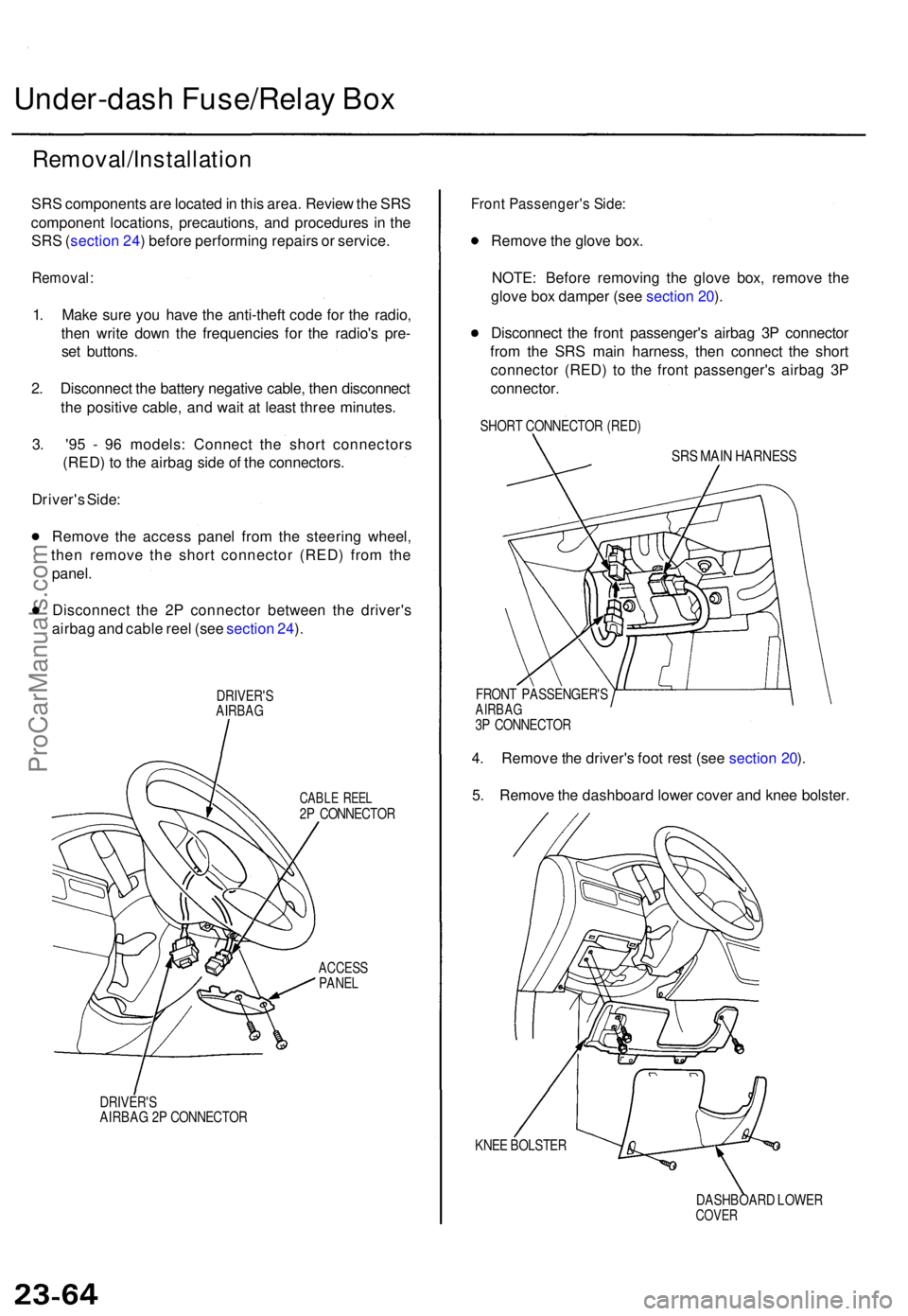
3 . '9 5 - 9 6 models : Connec t th e shor t connector s
(RED ) t o th e airba g sid e o f th e connectors .
Driver' s Side :
Remov e th e acces s pane l fro m th e steerin g wheel ,
the n remov e th e shor t connecto r (RED ) fro m th e
panel .
Disconnec t th e 2 P connecto r betwee n th e driver' s
airba g an d cabl e ree l (se e sectio n 24 ).
DRIVER' SAIRBAG
CABLE REE L2P CONNECTO R
ACCESSPANEL
DRIVER' SAIRBAG 2 P CONNECTO R
Front Passenger' s Side :
Remov e th e glov e box .
NOTE : Befor e removin g th e glov e box , remov e th e
glov e bo x dampe r (se e sectio n 20 ).
Disconnec t th e fron t passenger' s airba g 3 P connecto r
fro m th e SR S mai n harness , the n connec t th e shor t
connecto r (RED ) t o th e fron t passenger' s airba g 3 P
connector .
SHORT CONNECTO R (RED )
SRS MAI N HARNES S
FRONT PASSENGER' SAIRBAG3P CONNECTO R
4. Remov e th e driver' s foo t res t (se e sectio n 20 ).
5 . Remov e th e dashboar d lowe r cove r an d kne e bolster .
KNEE BOLSTE R
DASHBOARD LOWE R
COVER
ProCarManuals.com