Page 895 of 1771

Idle Spee d Settin g
Inspection/Adjustmen t
NOTE:
• Befor e settin g th e idl e speed , chec k th e followin g
items:
— Th e MI L ha s no t bee n reporte d on .
— Ignitio n timin g
— Spar k plug s
— Ai r cleane r
— PC V syste m
• (Canada ) Pul l th e parkin g brak e leve r up . Star t th e
engine , the n chec k tha t th e headlight s ar e off .
1 . Star t th e engine . Hol d th e engine at 3,00 0 rp m wit h
no loa d (transmissio n i n o r position ) unti l th e
radiato r fa n come s on , the n le t i t idle .
2 . Connec t a tachometer .
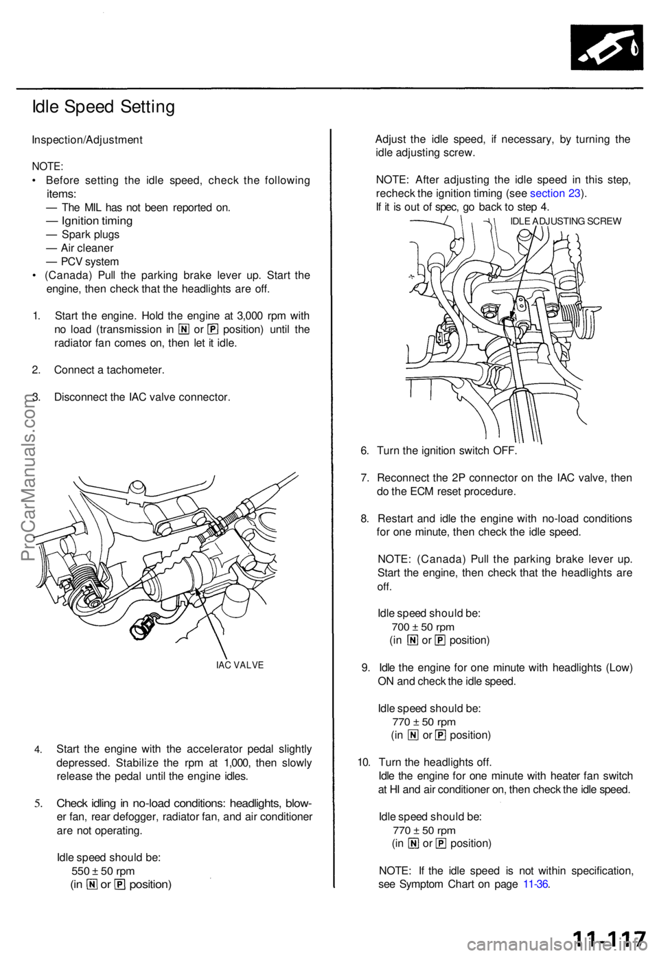
3 . Disconnec t th e IA C valv e connector .
IAC VALV E
4.
5.
Star t th e engin e wit h th e accelerato r peda l slightl y
depressed . Stabiliz e th e rp m a t 1,000 , the n slowl y
releas e th e peda l unti l th e engin e idles .
Check idlin g in no-loa d conditions : headlights , blow -
er fan , rea r defogger , radiato r fan , an d ai r conditione r
ar e no t operating .
Idl e spee d shoul d be :
550 ± 5 0 rp m
(in o r position )
Adjust th e idl e speed , i f necessary, by turnin g th e
idl e adjustin g screw .
NOTE : Afte r adjustin g th e idl e spee d i n thi s step ,
rechec k th e ignitio n timin g (se e sectio n 23 ).
I f i t i s ou t o f spec , g o bac k t o ste p 4 .
IDL E ADJUSTIN G SCRE W
6. Tur n th e ignitio n switc h OFF .
7 . Reconnec t th e 2 P connecto r o n th e IA C valve , the n
d o th e EC M rese t procedure .
8 . Restar t an d idl e th e engine with no-loa d condition s
fo r on e minute , the n chec k th e idl e speed .
NOTE : (Canada ) Pul l th e parkin g brak e leve r up .
Star t th e engine , the n chec k tha t th e headlight s ar e
off.
Idle spee d shoul d be :
700 ± 5 0 rp m
(in o r position )
9 . Idl e th e engin e fo r on e minut e wit h headlight s (Low )
O N an d chec k th e idl e speed .
Idl e spee d shoul d be :
770 ± 5 0 rp m
(in o r position )
10 . Tur n th e headlight s off .
Idl e th e engin e fo r on e minut e wit h heate r fa n switc h
a t H I an d ai r conditione r on , the n chec k th e idl e speed .
Idl e spee d shoul d be :
770 ± 5 0 rp m
(in o r position )
NOTE : I f th e idl e spee d i s no t withi n specification ,
se e Sympto m Char t o n pag e 11-36 .
ProCarManuals.com
Page 926 of 1771

Intake Ai r Syste m Emissio
n Contro l Syste m
Intake Ai r Bypas s (IAB ) Contro l
Syste m (cont'd )
Intake Ai r Bypas s (IAB ) Contro l Valv e Testin g
1. Chec k th e IA B contro l valv e shaf t fo r bindin g o r stick -
ing.
2. Chec k th e IA B contro l valv e fo r smoot h movement .
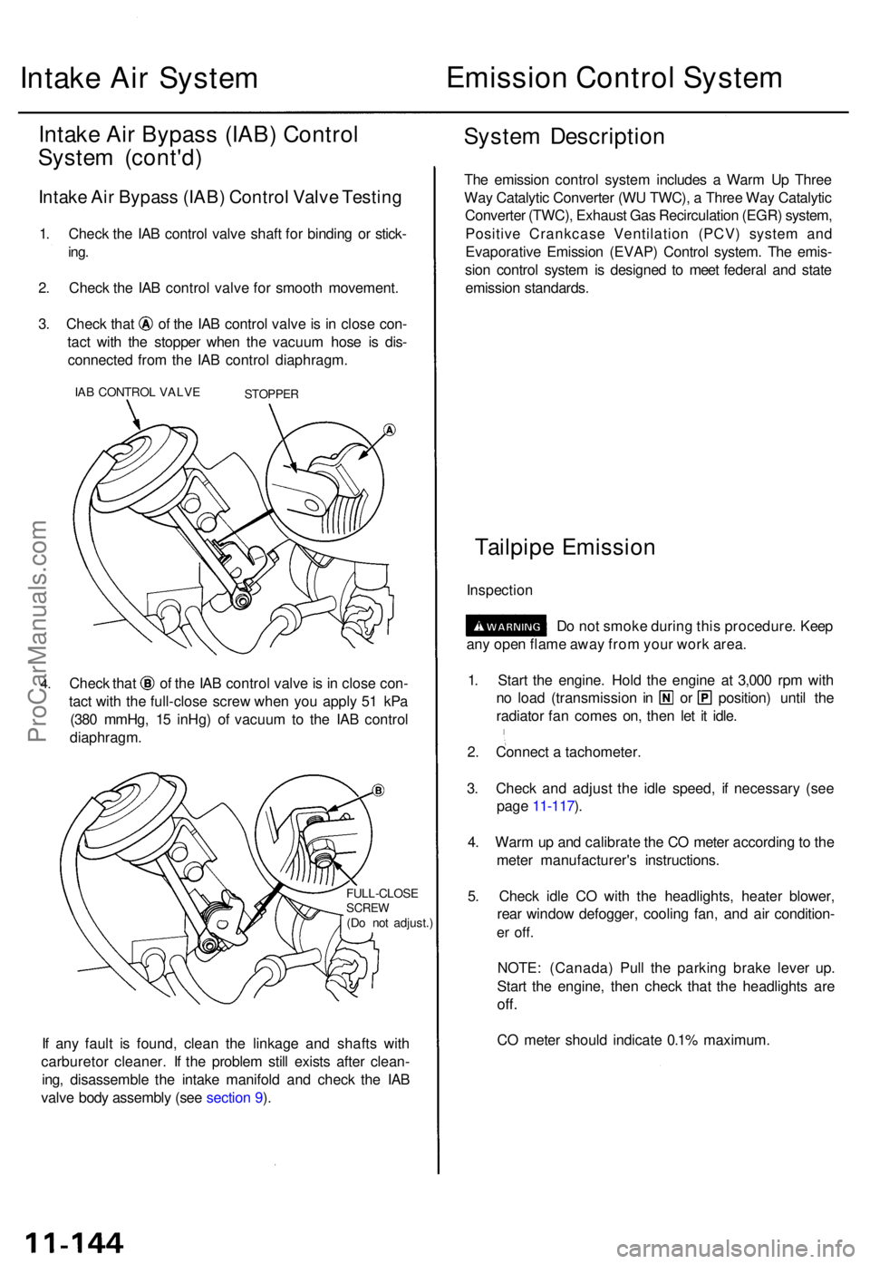
3. Chec k tha t o f th e IA B contro l valv e is i n clos e con -
tac t wit h th e stoppe r whe n th e vacuu m hos e i s dis -
connecte d fro m th e IA B contro l diaphragm .
IAB CONTRO L VALV ESTOPPE R
4.Chec k tha t o f th e IA B contro l valv e is in clos e con -
tac t wit h th e full-clos e scre w whe n yo u appl y 5 1 kP a
(38 0 mmHg , 1 5 inHg ) o f vacuu m to th e IA B contro l
diaphragm .
FULL-CLOS ESCREW(Do no t adjust. )
If an y faul t i s found , clea n th e linkag e an d shaft s wit h
carbureto r cleaner . I f th e proble m stil l exist s afte r clean -
ing , disassembl e th e intak e manifol d an d chec k th e IA B
valv e bod y assembl y (se e sectio n 9 ).
Syste m Descriptio n
The emissio n contro l syste m include s a War m U p Thre e
Wa y Catalyti c Converte r (W U TWC) , a Thre e Wa y Catalyti c
Converte r (TWC) , Exhaus t Ga s Recirculatio n (EGR ) system ,
Positiv e Crankcas e Ventilatio n (PCV ) syste m an d
Evaporativ e Emissio n (EVAP ) Contro l system . Th e emis -
sio n contro l syste m is designe d t o mee t federa l an d stat e
emissio n standards .
Tailpipe Emissio n
Inspectio n
Do no t smok e durin g thi s procedure . Kee p
an y ope n flam e awa y fro m you r wor k area .
1 . Star t th e engine . Hol d th e engin e a t 3,00 0 rp m wit h
no loa d (transmissio n i n o r position ) unti l th e
radiato r fa n come s on , the n le t i t idle .
2 . Connec t a tachometer .
3 . Chec k an d adjus t th e idl e speed , i f necessar y (se e
pag e 11-117 ).
4 . War m u p an d calibrat e th e C O mete r accordin g to th e
mete r manufacturer' s instructions .
5 . Chec k idl e C O wit h th e headlights , heate r blower ,
rea r windo w defogger , coolin g fan , an d ai r condition -
er off .
NOTE : (Canada ) Pul l th e parkin g brak e leve r up .
Star t th e engine , the n chec k tha t th e headlight s ar e
off.
CO mete r shoul d indicat e 0.1 % maximum .
ProCarManuals.com
Page 988 of 1771

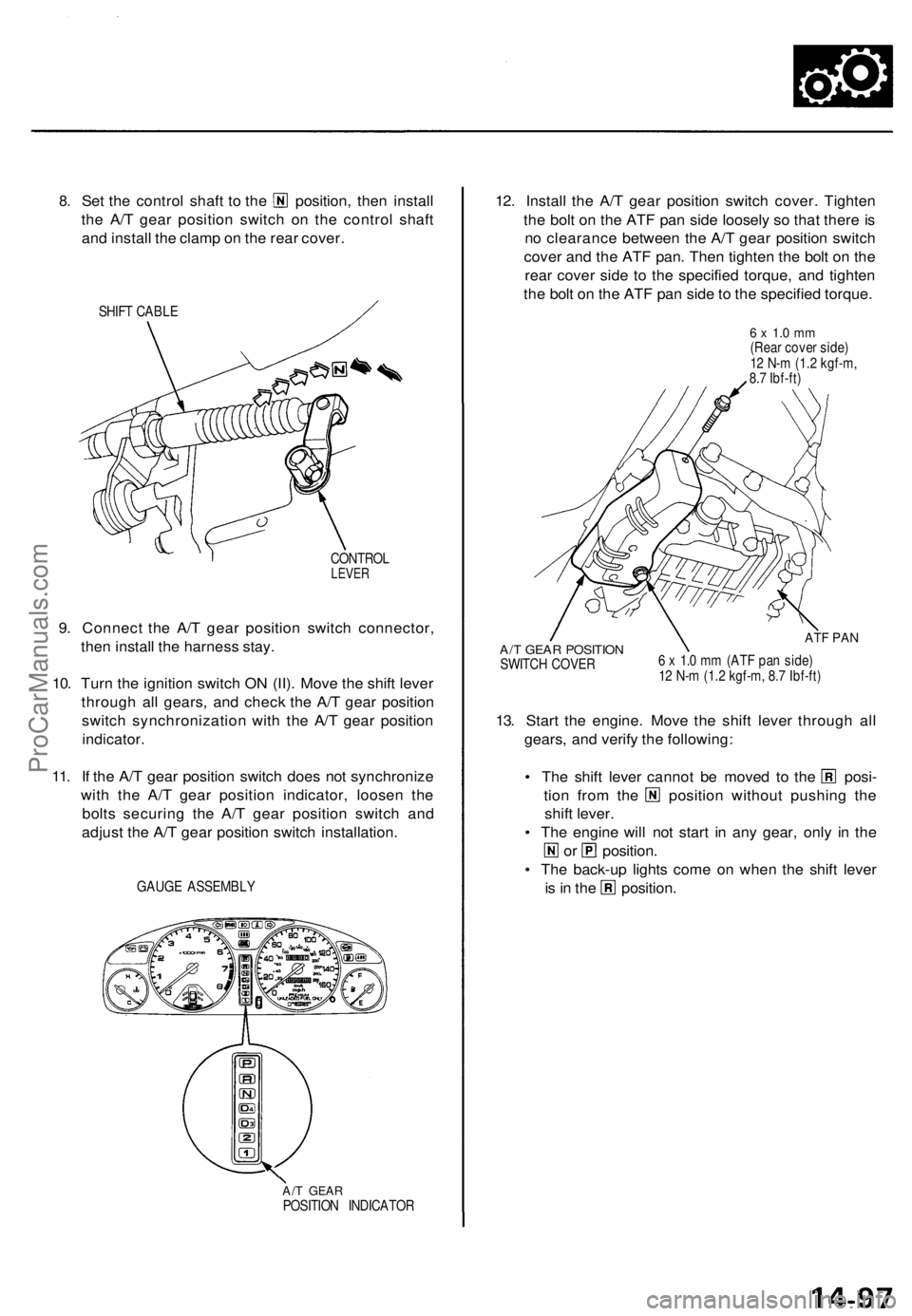
8.
Set the control shaft to the position, then install
the A/T gear position switch on the control shaft
and install the clamp on the rear cover.
SHIFT CABLE
CONTROL
LEVER
9. Connect the A/T gear position switch connector,
then install the harness stay.
10. Turn the ignition switch ON (II). Move the shift lever
through all gears, and check the A/T gear position
switch synchronization with the A/T gear position
indicator.
11. If the A/T gear position switch does not synchronize
with the A/T gear position indicator, loosen the
bolts securing the A/T gear position switch and
adjust the A/T gear position switch installation.
GAUGE ASSEMBLY
A/T GEAR
POSITION INDICATOR
12. Install the A/T gear position switch cover. Tighten
the bolt on the ATF pan side loosely so that there is
no clearance between the A/T gear position switch
cover and the ATF pan. Then tighten the bolt on the
rear cover side to the specified torque, and tighten
the bolt on the ATF pan side to the specified torque.
6 x 1.0 mm
(Rear cover side)
12 N-m (1.2 kgf-m,
8.7 Ibf-ft)
A/T GEAR POSITION
SWITCH COVER
ATF PAN
6 x 1.0 mm (ATF pan side)
12 N-m (1.2 kgf-m, 8.7 Ibf-ft)
13. Start the engine. Move the shift lever through all
gears, and verify the following:
• The shift lever cannot be moved to the posi-
tion from the position without pushing the
shift lever.
• The engine will not start in any gear, only in the
or position.
• The back-up lights come on when the shift lever
is in the position.ProCarManuals.com
Page 1296 of 1771
GAUGE ASSEMBLY
UNDER-HOOD FUSE/RELAY BOX
ABS INDICATOR LIGHT
BATTERY
(100 A) FUSE
IG (50 A) FUSE
STOP/ HORN
(20 A) FUSE
UNDER-DASH FUSE/RELAY BOX
UNDER-HOOD ABS FUSE/RELAY BOX
HEATER
CONTROL RELAY
(7.5 A) FUSE
BACK-UP LIGHTS/
METER LIGHTS
(SUN ROOF)
(10 A) FUSE
ECU (ECM)/
CRUISE CONTROL/
EAT ECU
(15 A) FUSE
ABS MOTOR (40 A) FUSE
ABS B1 (20 A) FUSE
ABS B2 (15 A) FUSE
ABS PUMP MOTOR RELAY
UNDER-DASH RELAY BOX
ABS UNIT (10 A) FUSE
REAR FAIL-SAFE RELAY
FRONT FAIL-SAFE RELAYProCarManuals.com
Page 1322 of 1771
ABS INDICATOR LIGHT
BATTERY
(100 A) FUSE
STOP/ HORN
(20 A) FUSE
IG (50 A) FUSE
UNDER-DASH FUSE/RELAY BOX
UNDER-HOOD ABS FUSE/RELAY BOX
HEATER
CONTROL RELAY
(7.5 A) FUSE
BACK-UP LIGHTS/
METER LIGHTS
(SUN ROOF)
(10 A) FUSE
ECU (ECM)/
CRUISE CONTROL/
EAT ECU
(15 A) FUSE
ABS MOTOR (30 A) FUSE
ABS B1 (20 A) FUSE
UNDER-DASH RELAY BOX
ABS PUMP MOTOR RELAY
ABS UNIT (7.5 A) FUSE
FAIL-SAFE RELAYProCarManuals.com
Page 1542 of 1771
Relay and Control Unit Locations
Dashboard (cont'd)
ABS FAIL-SAFE RELAY
('97-98 models)
ABS FRONT FAIL-SAFE RELAY
('95 - 96 models)
FOG LIGHT RELAY
BLOWER MOTOR
HIGH RELAY
ABS REAR
FAIL-SAFE RELAY
('95 - 96 models)
UNDER-DASH
RELAY BOX
LOW BEAM
CUT RELAY
(Canada)
POWER MIRROR
DEFOGGER RELAY
(Canada)
ECM
DAYTIME
RUNNING LIGHTS
CONTROL UNIT
(Canada)
BLOWER
MOTOR
RELAY
HORN RELAYProCarManuals.com
Page 1595 of 1771
Bulb Locations
GAUGE LIGHTS
(1.4
W x 2)
HIGH BEAM INDICATOR LIGHT (1.4 W)
SEAT BELT REMINDER LIGHT (1.4 W)
RIGHT TURN SIGNAL INDICATOR LIGHT (1.4 W)
MALFUNCTION INDICATOR LAMP
(MIL) (1.4
W)
LOW FUEL
INDICATOR LIGHT (3 W)
BRAKE SYSTEM LIGHT (1.4 W)
LEFT TURN SIGNAL INDICATOR LIGHT (1.4 W)
SRS INDICATOR LIGHT (1.4 W)
(On the SRS printed circuit board)
CHARGING SYSTEM LIGHT (1.4 W)
LOW ENGINE OIL PRESSURE
INDICATOR LIGHT (1.4 W)
ABS INDICATOR LIGHT (1.4 W)
DRL INDICATOR
LIGHT (1.4 W) (Canada)
CRUISE LIGHT (2 W)
A/T GEAR POSITION INDICATOR LIGHTS (1.12 W x 7)
GAUGE LIGHTS
(3.4
W x 2)
SAFETY
INDICATOR
LIGHTS
(1.12
W x 6)
GAUGE LIGHTS
(3.4
W x 3)ProCarManuals.com
Page 1605 of 1771
Brake System Indicator
Parking Brake Switch Test
1. Remove the center console, and disconnect the con-
nector from the switch.
2. Check for continuity between the terminal and body
ground in each switch position according to the table.
BRAKE LEVER
BODY
GROUND
POSITIVE
TERMINAL
NOTE (Canada): If the parking brake switch is OK,
but the brake system indicator does not function,
perform the input test for the daytime running
lights control unit.
Brake Fluid Level Switch Test
1. Remove the reservoir cap. Check that the float
moves up and down freely; if it doesn't, replace the
reservoir cap assembly.
2. Check for continuity between the terminals in each
switch position according to the table.
RESERVOIR CAP
FLOAT
Switch contacts closed
when float drops.
Switch contacts open at
proper fluid level.
UP POSITION
MAGNET
DOWN POSITION
DOWN
UPProCarManuals.com