1995 ACURA TL brake sensor
[x] Cancel search: brake sensorPage 1291 of 1771
Pump motor control:
The ABS control unit monitors the brake fluid pressure in the accumulator by the pressure switch ON/OFF signals. The
ABS control unit turns the pump on when the pressure in the accumulator drops, and stops the pump when the pressure
rises to the specified value.
If the pressure does not reach the specified value after the motor has operated continuously for a specified period, the
ABS control unit stops the motor and activates the ABS indicator light.
Self-diagnosis function:
The self-diagnosis function, provided in the sub-function of the ABS control unit, monitors the main system functions by
constantly transmitting the data between the two Central Processing Units (CPUs). When an abnormality is detected, the
ABS control unit turns the ABS indicator light on and stops the ABS, although the basic brake system continues to operate
normally.
When the ABS control unit detects an abnormality with the ABS and turns the ABS indicator light on, the diagnostic trou-
ble code (DTC), which shows the problem part or unit, is recorded in the control unit. The DTC can be read by the blinking
frequency of the ABS indicator light.
Fail-safe function:
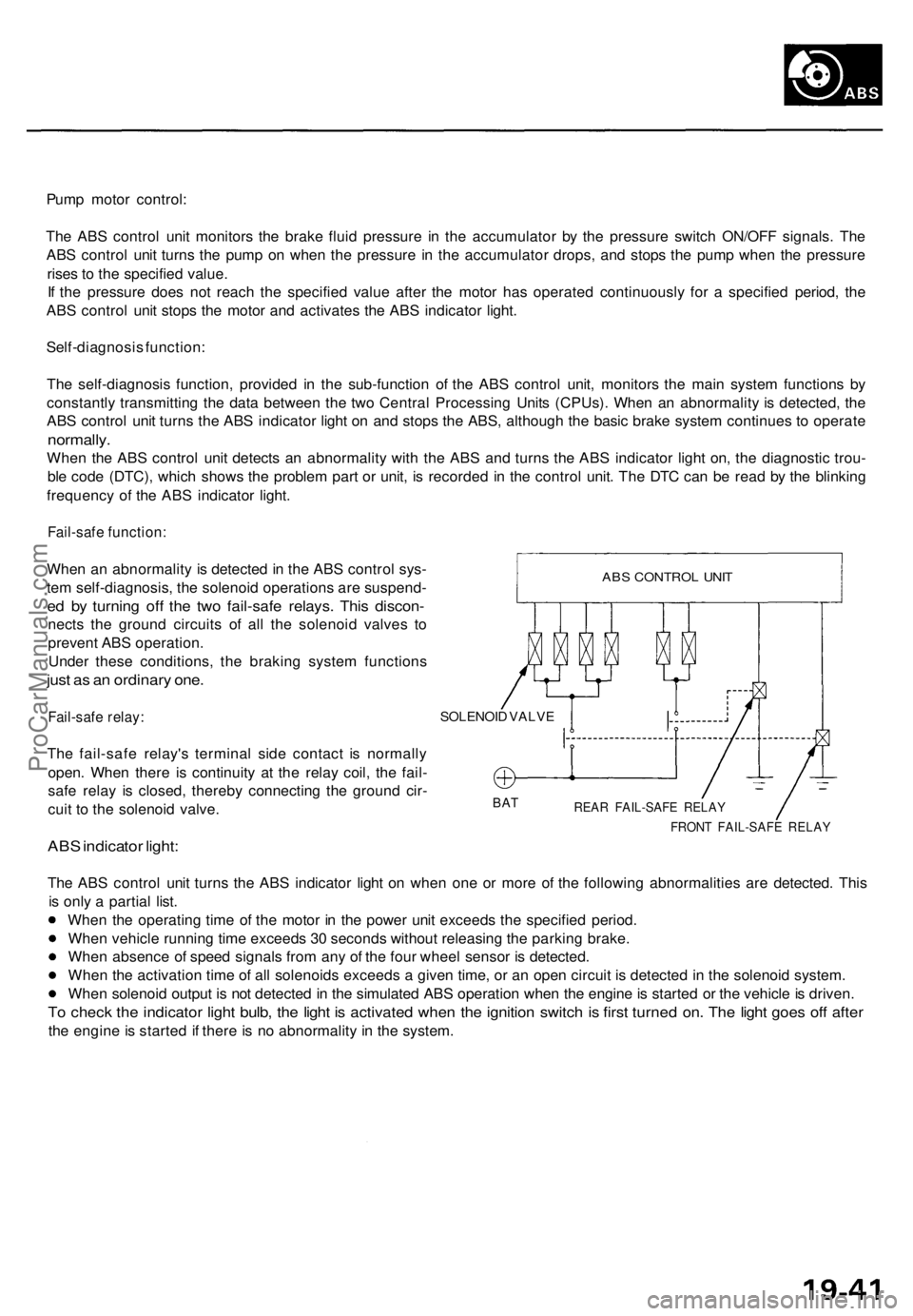
When an abnormality is detected in the ABS control sys-
tem self-diagnosis, the solenoid operations are suspend-
ed by turning off the two fail-safe relays. This discon-
nects the ground circuits of all the solenoid valves to
prevent ABS operation.
Under these conditions, the braking system functions
just as an ordinary one.
Fail-safe relay:
The fail-safe relay's terminal side contact is normally
open. When there is continuity at the relay coil, the fail-
safe relay is closed, thereby connecting the ground cir-
cuit to the solenoid valve.
ABS indicator light:
SOLENOID VALVE
BAT
REAR FAIL-SAFE RELAY
FRONT FAIL-SAFE RELAY
The ABS control unit turns the ABS indicator light on when one or more of the following abnormalities are detected. This
is only a partial list.
When the operating time of the motor in the power unit exceeds the specified period.
When vehicle running time exceeds 30 seconds without releasing the parking brake.
When absence of speed signals from any of the four wheel sensor is detected.
When the activation time of all solenoids exceeds a given time, or an open circuit is detected in the solenoid system.
When solenoid output is not detected in the simulated ABS operation when the engine is started or the vehicle is driven.
To check the indicator light bulb, the light is activated when the ignition switch is first turned on. The light goes off after
the engine is started if there is no abnormality in the system.
ABS CONTROL UNITProCarManuals.com
Page 1295 of 1771
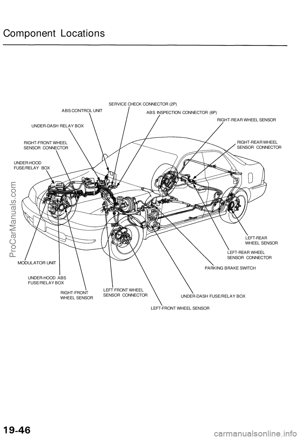
Component Locations
ABS CONTROL UNIT
UNDER-DASH RELAY BOX
RIGHT-FRONT WHEEL
SENSOR CONNECTOR
UNDER-HOOD
FUSE/RELAY BOX
SERVICE CHECK CONNECTOR (2P)
ABS INSPECTION CONNECTOR (6P)
MODULATOR UNIT
UNDER-HOOD ABS
FUSE/RELAY BOX
RIGHT-REAR WHEEL SENSOR
RIGHT-REAR WHEEL
SENSOR CONNECTOR
LEFT-REAR
WHEEL SENSOR
LEFT-REAR WHEEL
SENSOR CONNECTOR
RIGHT-FRONT
WHEEL SENSOR
LEFT FRONT WHEEL
SENSOR CONNECTOR
PARKING BRAKE SWITCH
UNDER-DASH FUSE/RELAY BOX
LEFT-FRONT WHEEL SENSORProCarManuals.com
Page 1321 of 1771
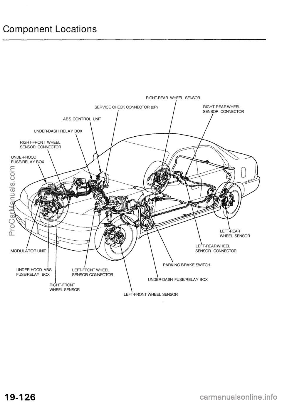
Component Locations
RIGHT-REAR WHEEL SENSOR
SERVICE CHECK CONNECTOR (2P)
ABS CONTROL UNIT
RIGHT-REAR WHEEL
SENSOR CONNECTOR
UNDER-DASH RELAY BOX
RIGHT-FRONT WHEEL
SENSOR CONNECTOR
UNDER-HOOD
FUSE/RELAY BOX
LEFT-REAR
WHEEL SENSOR
MODULATOR UNIT
UNDER-HOOD ABS
FUSE/RELAY BOX
LEFT-REAR WHEEL
SENSOR CONNECTOR
PARKING BRAKE SWITCH
UNDER-DASH FUSE/RELAY BOX
RIGHT-FRONT
WHEEL SENSOR
LEFT-FRONT WHEEL SENSOR
LEFT-FRONT WHEEL
SENSOR CONNECTORProCarManuals.com
Page 1614 of 1771
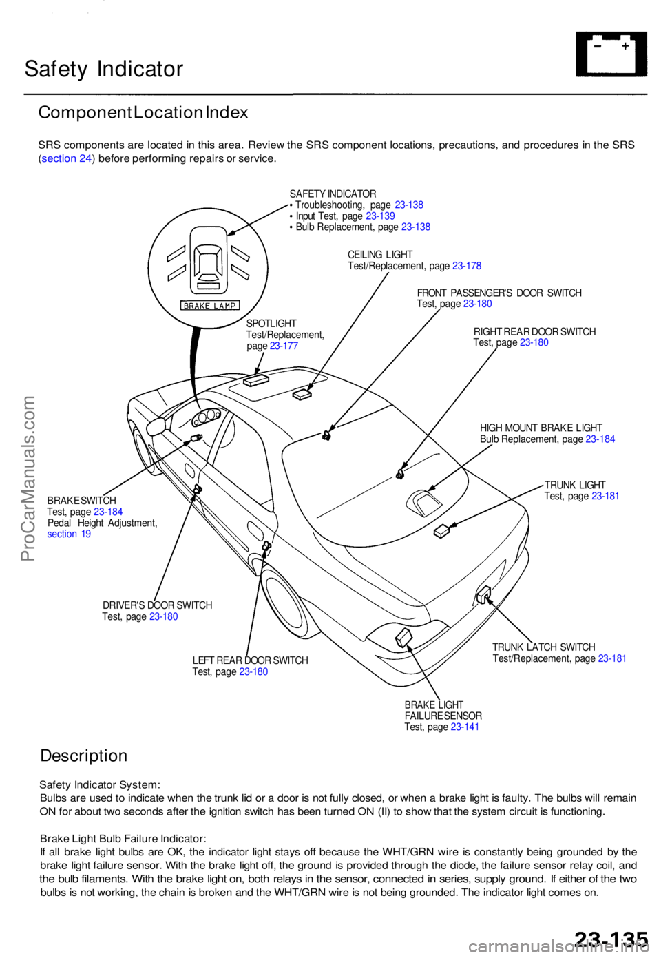
Safety Indicato r
Componen t Locatio n Inde x
SRS component s ar e locate d in thi s area . Revie w th e SR S componen t locations , precautions , an d procedure s i n th e SR S
( sectio n 24 ) befor e performin g repair s o r service .
SAFETY INDICATO R
Troubleshooting , pag e 23-13 8
Inpu t Test , pag e 23-13 9
Bul b Replacement , pag e 23-13 8
CEILIN G LIGH T
Test/Replacement , pag e 23-17 8
FRON T PASSENGER' S DOO R SWITC H
Test , pag e 23-18 0
RIGH T REA R DOO R SWITC H
Test , pag e 23-18 0
BRAK E SWITC H
Test , pag e 23-18 4
Peda l Heigh t Adjustment ,
sectio n 1 9 HIG
H MOUN T BRAK E LIGH T
Bul b Replacement , pag e 23-18 4
TRUN K LIGH T
Test , pag e 23-18 1
DRIVER' S DOO R SWITC H
Test , pag e 23-18 0
LEFT REA R DOO R SWITC H
Test , pag e 23-18 0 TRUN
K LATC H SWITC H
Test/Replacement , pag e 23-18 1
BRAKE LIGH TFAILUR E SENSO R
Test , pag e 23-14 1
Descriptio n
Safety Indicato r System :
Bulb s ar e use d to indicat e whe n th e trun k li d o r a doo r i s no t full y closed , o r whe n a brak e ligh t i s faulty . Th e bulb s wil l remai n
O N fo r abou t tw o second s afte r th e ignitio n switc h ha s bee n turne d O N (II ) t o sho w tha t th e syste m circui t i s functioning .
Brak e Ligh t Bul b Failur e Indicator :
I f al l brak e ligh t bulb s ar e OK , th e indicato r ligh t stay s of f becaus e th e WHT/GR N wir e i s constantl y bein g grounde d b y th e
brak e ligh t failur e sensor . Wit h th e brak e ligh t off , th e ground is provide d throug h th e diode , th e failur e senso r rela y coil , an d
the bul b filaments . Wit h th e brak e ligh t on , bot h relay s in th e sensor , connecte d in series , suppl y ground . I f eithe r o f th e tw o
bulb s is no t working , th e chai n is broke n an d th e WHT/GR N wir e is no t bein g grounded . Th e indicato r ligh t come s on .
SPOTLIGH T
Test/Replacement ,
pag e 23-17 7
ProCarManuals.com
Page 1617 of 1771
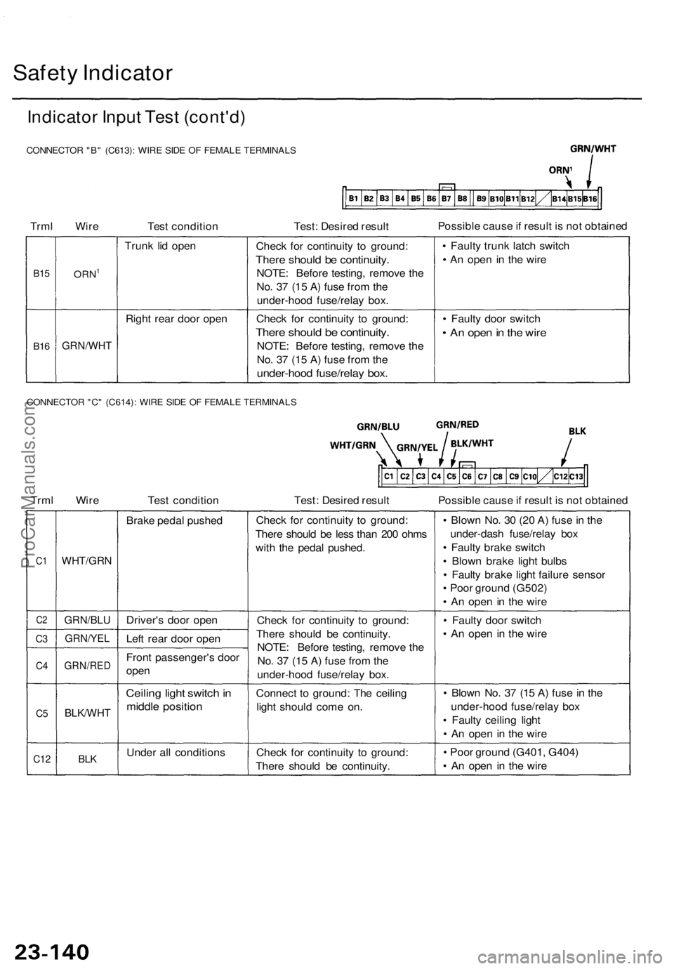
Safety Indicator
Indicator Input Test (cont'd)
CONNECTOR "B" (C613): WIRE SIDE OF FEMALE TERMINALS
Trml Wire
Test condition
Test: Desired result
Possible cause if result is not obtained
B15
B16
ORN1
GRN/WHT
Trunk lid open
Right rear door open
Check for continuity to ground:
There should be continuity.
NOTE: Before testing, remove the
No. 37 (15 A) fuse from the
under-hood fuse/relay box.
Check for continuity to ground:
There should be continuity.
NOTE: Before testing, remove the
No. 37 (15 A) fuse from the
under-hood fuse/relay box.
• Faulty trunk latch switch
• An open in the wire
• Faulty door switch
• An open in the wire
CONNECTOR "C" (C614): WIRE SIDE OF FEMALE TERMINALS
Trml Wire
Test condition
Test: Desired result
Possible cause if result is not obtained
C1
C2
C3
C4
C5
C12
WHT/GRN
GRN/BLU
GRN/YEL
GRN/RED
BLK/WHT
BLK
Brake pedal pushed
Driver's door open
Left rear door open
Front passenger's door
open
Ceiling light switch in
middle position
Under all conditions
Check for continuity to ground:
There should be less than 200 ohms
with the pedal pushed.
Check for continuity to ground:
There should be continuity.
NOTE: Before testing, remove the
No. 37 (15 A) fuse from the
under-hood fuse/relay box.
Connect to ground: The ceiling
light should come on.
Check for continuity to ground:
There should be continuity.
• Blown No. 30 (20 A) fuse in the
under-dash fuse/relay box
• Faulty brake switch
• Blown brake light bulbs
• Faulty brake light failure sensor
• Poor ground (G502)
• An open in the wire
• Faulty door switch
• An open in the wire
• Blown No. 37 (15 A) fuse in the
under-hood fuse/relay box
• Faulty ceiling light
• An open in the wire
• Poor ground (G401, G404)
• An open in the wireProCarManuals.com
Page 1618 of 1771
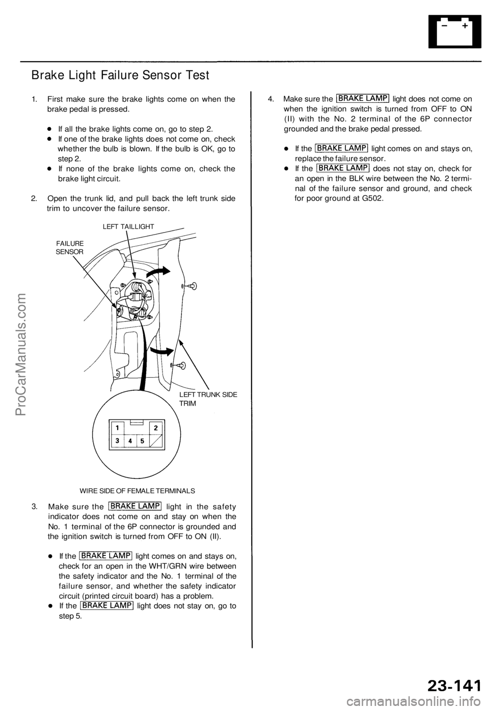
Brake Ligh t Failur e Senso r Tes t
1. Firs t mak e sur e th e brak e light s com e o n whe n th e
brak e peda l i s pressed .
I f al l th e brak e light s com e on , g o t o ste p 2 .
I f on e o f th e brak e light s doe s no t com e on , chec k
whethe r th e bul b i s blown . I f th e bul b is OK , g o t o
ste p 2 .
I f non e o f th e brak e light s com e on , chec k th e
brak e ligh t circui t.
2 . Ope n th e trun k lid , an d pul l bac k th e lef t trun k sid e
tri m to uncove r th e failur e sensor .
3.
LEF T TAILLIGH T
FAILURESENSOR
LEFT TRUN K SID ETRIM
WIR E SID E O F FEMAL E TERMINAL S
Make sur e th e ligh t i n th e safet y
indicato r doe s no t com e o n an d sta y o n whe n th e
No . 1 termina l o f th e 6 P connecto r i s grounde d an d
th e ignitio n switc h is turne d fro m OF F to O N (II) .
If th e ligh t come s o n an d stay s on ,
chec k fo r a n ope n i n th e WHT/GR N wir e betwee n
th e safet y indicato r an d th e No . 1 termina l o f th e
failur e sensor , an d whethe r th e safet y indicato r
circui t (printe d circui t board ) ha s a problem .
If th e ligh t doe s no t sta y on , g o t o
ste p 5 .
4. Mak e sur e th e ligh t doe s no t com e o n
whe n th e ignitio n switc h i s turne d fro m OF F t o O N
(II ) wit h th e No . 2 termina l of the 6 P connecto r
grounde d an d th e brak e peda l pressed .
If th e ligh t come s o n an d stay s on ,
replac e th e failur e sensor .
If th e doe s no t sta y on , chec k fo r
a n ope n in th e BL K wir e betwee n th e No . 2 termi -
na l o f th e failur e senso r an d ground , an d chec k
fo r poo r groun d a t G502 .
ProCarManuals.com
Page 1716 of 1771
Description
The cruise control system uses mechanically and electri-
cally operated devices to maintain vehicle speed at a
setting selected by the driver.
The cruise control unit receives command signals from
the cruise control main switch and the cruise control
set/resume/cancel switch. It receives information about
operating conditions from the brake switch, ECM, vehi-
cle speed sensor (VSS), or the A/T gear position switch.
The cruise control unit sends operational signals to the
devices that regulate the throttle position. The throttle
position maintains the selected vehicle speed.
Essentially, the control unit compares the actual speed
of the vehicle to the selected speed. Then, the control
unit uses the result of that comparison to open or close
the throttle.
The brake switch releases the system's control of the
throttle at the instant the driver depresses the brake
pedal. The switch sends an electronic signal to the con-
trol unit when the brake pedal is depressed; the control
unit responds by allowing the throttle to close. The A/T
gear position switch sends a disengage signal input to
the control unit that also allows the throttle to close.
Operation:
The cruise control system will set and automatically
maintain any speed above 25 mph (40 km/h). To set a
speed, make sure that the main switch is in the "ON"
position. After reaching the desired speed, press the set
switch. The cruise control unit will receive a set signal
and, in turn, will actuate the cruise control actuator. If
you depress the set switch is when the cruise control
system is on, the "cruise light", an indicator in the
gauge assembly, will come on. You can cancel the
cruise control system by depressing the cancel switch or
by pushing the main switch to "OFF". This removes
power to the control unit and erases the set speed from
memory. If the system is disengaged temporarily by the
brake switch or the A/T gear position switch and vehicle
speed is still above 25 mph (40 km/h), press the resume
switch. With the resume switch depressed and the set
memory retained, the vehicle will automatically return
to the previous set speed.
For gradual acceleration without depressing the acceler-
ator pedal, push the resume switch down and hold it
there until the desired speed is reached. This will send
an acceleration signal to the control unit. When the
switch is released, the system will be reprogrammed for
the new speed. To slow the vehicle down, depress the
set switch. This will send a deceleration signal to the
control unit, causing the vehicle to coast. When you
reach the desired speed, release the set switch. This will
reprogram the system for the new speed.ProCarManuals.com