Page 923 of 1708
MAIN FUSE BLOCK FUSE BLOCK C-2 6 PMRmAIN L/R CONTROL MMULE (ENGINE1 (YCTIaN 0-1cl .CIGARETTE LIGHTER .INTERIOR LIGHT .REAR WINDOW OEFROSTER INSTRUMENT WINCmW DEFROSTER WOR SWITCHES (SECTIDN TI -05 REAR WINX)W DEFROSTER RELAY(R) -00 CIGARETTE LIGHTER (I) I-m REAR (R) -REAR NO. 2 (~21 11-07 REAR W INWW DEFROSTER IR21 1-09 INTERIOR LIGHT (I1 E-10 REAR WINOOW DEFROSTER SWITCH (It 1 Gartner Banana
Page 934 of 1708
REAR WINDOW DEFROSTER REAR WINDOW DEFROSTER STRUCTURAL VIEW 1. Rear window defroster L/ 2. Rear window defroster switch 3. Rear window defroster relay 4. Rear window defroster timer unit DESCRIPTION The rear window defroster switch is included in the heater control switch assembly. Gartner Banana
Page 935 of 1708
FUSE BCOCK IX-031 I 1,05);;;! rAR WINOOW OEFROSTER 1-05 --: RELAY FUSE BLOCK 1-2 .CIGARETTE LIGHTER .INTERIOR LIGHT .REAR WINDOW DEFROSTER MAIN FUSE BLOCK FUSE BLOCK W/R (F) -- ;; ROOM L/R (FI IX-04 'OA &g [x-ZZI 1 - eh FUSE CONTROL MOOUCE (EWGINEI (SECTION 8- tc) INSTRVMENT CLUSTER (SECTION C-a) t OOW SWITCHES (SECTION T) INTERIOR LIGHT OFF. ON !;. (I1 OB CIGARETTE L .IGHTER (I) 1-09 INTERIOR LIGHT (11 I I Z-10 REAR WINOOW DEFROSTER SWITCH (I) I Gartner Banana
Page 936 of 1708
REAR WINDOW DEFROSTER T u Symptom: Rear window defroster does not operate. 9MUOTX-232 Step 1 1. Check the following fuses. I Fuse Amperage I Location I 2. If all the fuses are OK, go to Step 2. 3. If a fuse is burned out, replace it. Check and repair the wire harness, if necessary. R.DEF HEATER -- M: Continuity 20A 30A Step 2 1. Disconnect the rear window defroster relay. 2. Apply battery positive voltage and check for continuity between terminals of the relay. B+: Battery positive voltage 3. If correct install the rear window defroster relay and go to Step 3. 4. If not as specified, replace the rear window defroster relay. Fuse box No.2 Main fuse block Step 1 2 C Terminal D 0 GND B 0 B+ A 0 C 0 Gartner Banana
Page 937 of 1708

T REAR WINDOW DEFROSTER Step 3 1. Turn the ignition switch to on. 2. Turn the rear window defroster switch on. 3. Check the voltage at the terminal wires of the rear win- d dow defroster rday connector. B+: Battery positive voltage Terminal (uB) c (R) Step 4 Check if the heater operates in the first position. I Operation I Action I Voltage B+ other NG Repair wiring harness (Heater switch- Rear window defrostertimer unit) Action Check C terminal Repair wiring harness (HEATER fuse - Relav) B+ Other . , Go to Step 4 Go to Step 5 I Step 5 Check the voltage at the rear window defroster connec- tors. Check A terminal Repair wiring harness (DEFOG fuse - Relavl A (w) B+: Battery positive voltage B+ Other Terminal I Voltage I Action B+ I Check C terminal other If all above-mentioned parts are normal, replace the rear window defroster timer unit. Repair wiring harness (Defroster - Defroster timer unit) c (W) A (B) . B+ Other B+ Other Check A terminal Repair wiring harness (Relay- Defroster) Repair wiring harness (Defroster - GND) Repair defroster filament Gartner Banana
Page 938 of 1708

REAR WINDOW DEFROSTER T BATTERY POSITIVE VOLTAGE 45UOTX-18C -- FAULTY PORTION OV BATTERY POSITIVE VOLTAGE 45UOTX-18; Rear Window Defroster Switch (Refer to section U.) Rear Window Defroster Filament 1. Turn the rear window defroster switch ON. 2. Connect the (+) terminal of a voltmeter to the center of each filament and the (-) terminal to the body. The stan- dard voltage at the center of each filament is approx. 6V. If the meter indication is high, there is a short circuit be- tween the center and the grounded side of the filament. If the indication is low or zero, the fault is between the center and positive side. REPAIRING FILAMENT Caution Use only paint thinner or ethyl alcohol for clean- ing. Other solvents can damage the surrounding filament. 1. Use paint thinner or ethyl alcohol to clean the damage section of the filament. 2. Apply tape to both sides of the damaged section of fila- ment. 3. Using a small brush or marking pen, apply silver paint (part no. 2835 77 600) or equivalent to the damaged sec- tion. 4. Use a blow dryer heated to 60°C (140°F) for 30 minutes or let the paint set for 24 hours at 20°C (68°F) to let it dry completely. Do not use the rear window defroster until the paint is dry. Gartner Banana
Page 1090 of 1708

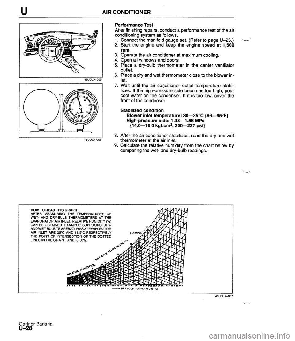
u AIR CONDITIONER Performance Test After finishing repairs, conduct a performance test of the air conditioning system as follows. 1. Connect the manifold gauge set. (Refer to page U-25.) 2. Start the engine and keep the engine speed at 1,500 rpm. 3. Operate the air conditioner at maximum cooling. 4. Open all windows and doors. 5. Place a dry-bulb thermometer in the center ventilator outlet. 6. Place a dry and wet thermometer close to the blower in- let. 7. Wait until the air conditioner outlet temperature stabi- lizes. If the high-pressure side becomes too high, pour cool water on the condenser. If it is too low, cover the front of the condenser. Stabilized condition Blower inlet temperature: 30-35°C (86-95°F) High-pressure side: 1.38-1.56 MPa (1 4.0-1 6.0 kgflcm*, 200-227 psi) 8. After the air conditioner stabilizes, read the dry and wet thermometer at the air inlet. 9. Calculate the relative humidity from the chart below by comparing the wet- and dry-bulb readings. Gartner Banana
Page 1123 of 1708

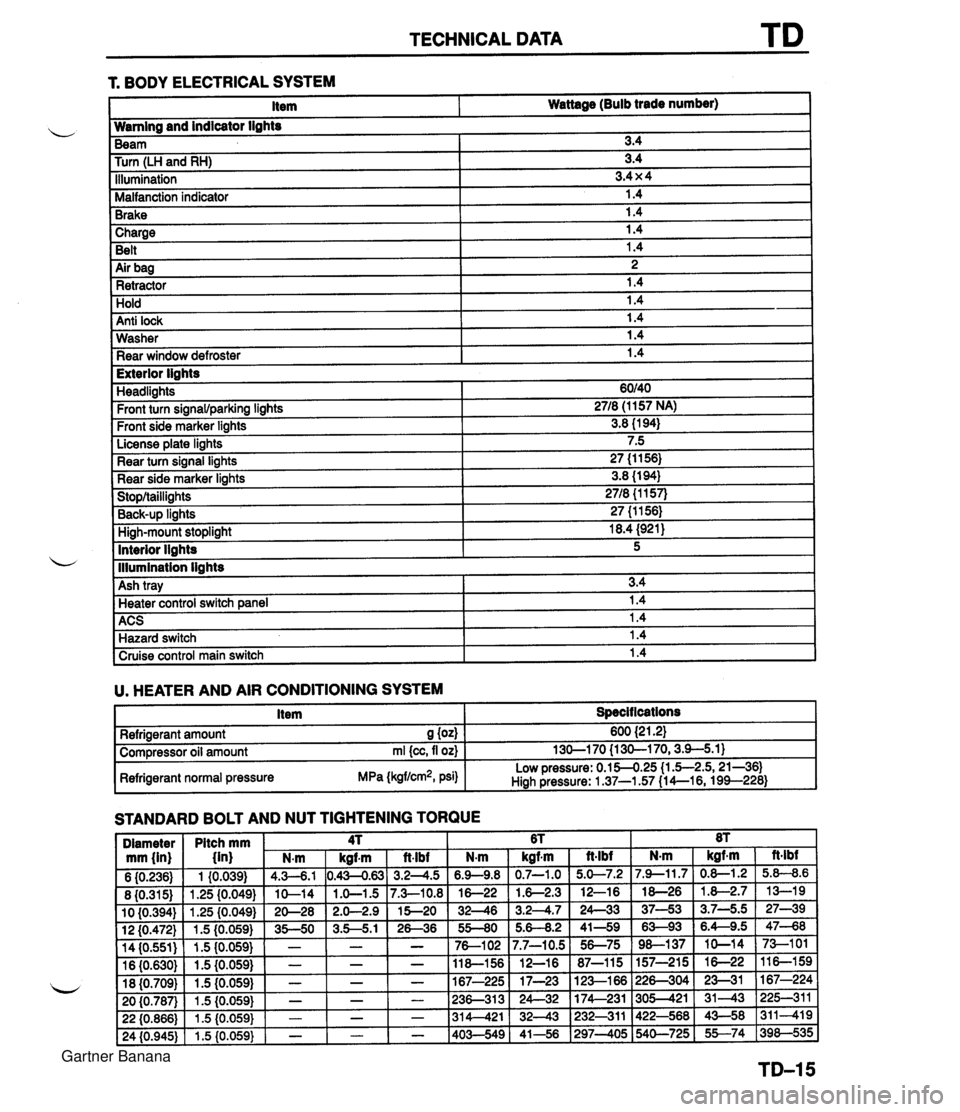
TECHNICAL DATA 1 Charge I 1.4 Belt 1.4 r. BODY ELECTRICAL SYSTEM 1 Air bag I 2 1 Retractor 1.4 Item Wattage (Bulb trade number) Hold Anti lock Wamlng and indicator lights 1.4 1.4 Washer Rear window defroster Beam Turn (LH and RH) Illumination Malfanction indicator Brake 1.4 1.4 I Exterior lights 3.4 3.4 3.4 x 4 1.4 1.4 Headlights Front turn signawparking lights Front side marker lights License plate lights Rear turn signal lights Rear side marker lights Stop/taillights Back-UP linhts High-mount stoplight I 18.4 (921) ACS 1 1.4 Hazard switch 1.4 60140 2718 (1 157 NA) 3.8 (1 94) 7.5 27 (1 1 56) 3.8 (1 94) 2718 {I 157) 27 (1 1561 Interior llahts - I lllumination lights I Cruise control main switch I 1.4 I 5 Ash tray U. HEATER AND AIR CONDITIONING SYSTEM I Item I Specit lcations I 3.4 Heater control switch ane el I 1.4 STANDARD BOLT AND NUT TIGHTENING TORQUE Refrigerant amount S (04 Compressor oil amount rnl {cc, fl oz) Refrigerant normal pressure MPa (kgflcm2, psi) 600 {2 1.21 130-1 70 {I 30-1 70,3.9-5.1) Low pressure: 0.154.25 (1 .5-2.5,21-361 Hiah Pressure: 1 37-1.57 (1 4--16, 199--228) Gartner Banana