Page 348 of 1708

CLUTCH RELEASE CYLINDER H Installation Note Clutch pipe 1. Modify the clutch pipe tightening torque to allow for use of a torque wrench-SST combination. (Refer to section GI "Torque Formulas".) 2. Tighten the clutch pipe by using the SST. Tightening torque: 12.8-21.5 N-m (1 30-220 kgfam, 11%-190 in-lbf) Air Bleeding After installation, bleed the clutch system. (Refer to page H-9.) OVERHAUL 1. Disassemble in the order shown in the figure, referring to Disassembly Note. 2. lnspect all parts and repair or replace as necessary. Warning Using compressed air can cause dirt and other particles to fly out, causing injury to the eyes. Wear protective eye wear whenever using compressed air. 3. Wipe all parts, and clean all ports, passages, and inner parts with compressed air. 4. Assemble in the reverse order of disassembly. 1. Boot 5. Bleeder cap 2. Push rod 6. Bleeder screw 3. Piston and cup assembly 7. Steel ball Disassembly Note . . . . . . . . . . . . . . . below 8. Release cylinder body Inspect for wear, scoring, and cracks Inspect cylinder bore for scoring and corro- 4. Spring sion Disassembly Note Piston and cup assembly Warning Applying compressed air to the cylinder assem- bly can make the contents suddenly pop out, possibly causing injury. Hold a rag over the cylin- der opening when using compressed air. Remove the piston-and-cup assembly by applying com- pressed air through the clutch pipe installation hole. Gartner Banana
Page 349 of 1708
H CLUTCH UNIT CLUTCH UNlT PREPARATION SST 49 E011 1AO Brake set, ring gear 49 E011 104 Collar (Part of 49 EOll 1AO) 49 SEOl 310A 0 Clutch disc centering tool 49 1285 073 Chuck (Part of 49 1285 071) For holding ring gear For holding ring gear For removal and installation of clutch disc For removal of pilot bearing 49 EOll 103 Shaft (Part of 49 EOll 1AO) 49 E011 105 Stopper (Part of 49 E011 1 AO) 49 1 285 071 Puller, bearing For holding ring gear For holding ring gear For removal of pilot bearing REMOVAL / INSTALLATION Note The clutch release cylinder can be removed from the transaxle with the clutch pipe connected. 1. Remove in the order shown in the figure, referring to Removal Note. 2. Install in the reverse order of removal, referring to Installation Note. Gartner Banana
Page 350 of 1708
CLUTCH UNIT H 97-1 02 {O&-10.5,71-75.9) 18--26 {I .6-2.7,14-19) (MORI WHITE TA No.2 OR EQUIVALENT ORGANIC MOLYBDENUM GREASE) 1. Clutch release cylinder 2. Transmission Service ..................... section J 3. Boot 4. Clutch release collar Inspection ................. page H-17 5. Clutch release fork 6. Clutch cover Removal Note ............. page H-16 Inspection ................. page H-17 Installation Note ........... page H-17 7. Clutch disc Removal Note ............. page H-16 Inspection ................. page H-17 Installation Note ........... page H-17 8. Pilot bearing Inspection ................. page H-18 Removal Note ............. page H-16 Installation Note ........... page H-16 9. Flywheel Removal Note ............. page H-16 Inspection ................. page H-18 Installation Note ........... page H-16 Gartner Banana
Page 351 of 1708

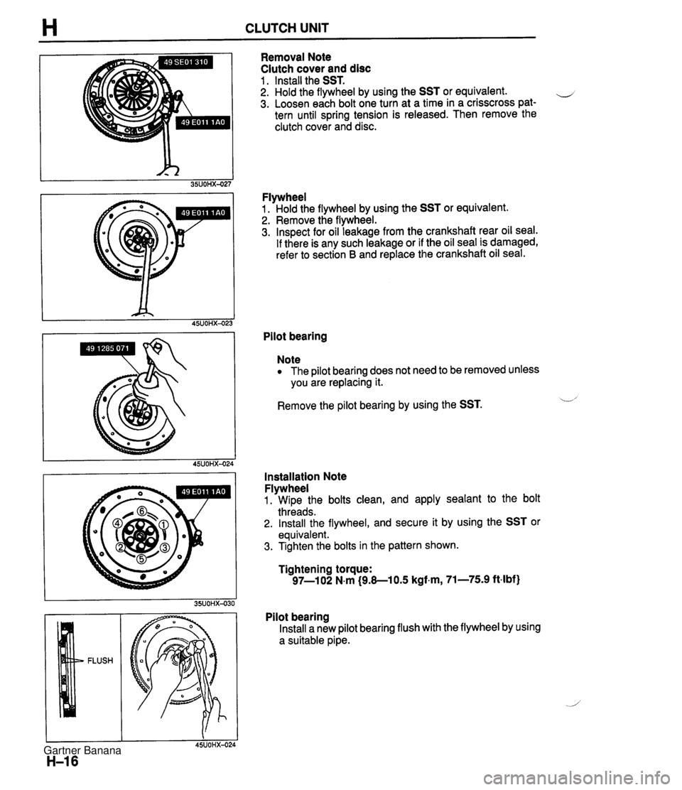
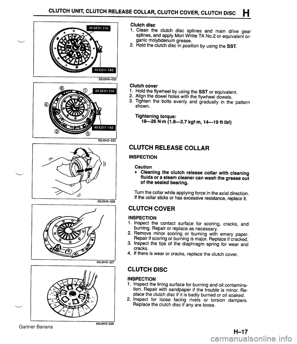
H CLUTCH UNIT Removal Note Clutch cover and disc 1 . Install the SST. 2. Hold the flywheel by using the SST or equivalent. e 3. Loosen each bolt one turn at a time in a crisscross pat- tern until spring tension is released. Then remove the clutch cover and disc. Flywheel 1. Hold the flywheel by using the SST or equivalent. 2. Remove the flywheel. 3. Inspect for oil leakage from the crankshaft rear oil seal. If there is any such leakage or if the oil seal is damaged, refer to section B and replace the crankshaft oil seal. Pilot bearing Note The pilot bearing does not need to be removed unless you are replacing it. Remove the pilot bearing by using the SST. L' Installation Note Flywheel 1. Wipe the bolts clean, and apply sealant to the bolt threads. 2. Install the flywheel, and secure it by using the SST or equivalent. 3. Tighten the bolts in the pattern shown. Tightening torque: 97-1 02 N.m (9.8-1 0.5 kgf.m, 71-75.9 ft-lbf) Pilot bearing Install a new pilot bearing flush with the flywheel by using a suitable pipe. Gartner Banana
Page 352 of 1708

CLUTCH UNIT, CLUTCH RELEASE COLLAR, CLUTCH COVER, CLUTCH DlSC H Clutch disc 1. Clean the clutch disc splines and main drive gear splines, and apply Mori White TA No.2 or equivalent or- ganic molybdenum grease. 2. Hold the clutch disc in position by using the SST. Clutch cover 1. Hold the flywheel by using the SST or equivalent. 2. Align the dowel holes with the flywheel dowels. 3. Tighten the bolts evenly and gradually in the pattern shown. Tightening torque: 18-26 N.m (1.8-2.7 kgf.m, 14--19 ft.lbf} CLUTCH RELEASE COLLAR INSPECTION Caution Cleaning the clutch release collar with cleaning fluids or a steam cleaner can wash the grease out of the sealed bearing. Turn the collar while applying force in the axial direction. If the collar sticks or has excessive resistance, replace it. CLUTCH COVER INSPECTION 1. lnspect the contact surface for scoring, cracks, and burning. Repair or replace as necessary. 2. Remove minor scoring or burning with emery paper. Repair if scoring or burning is major. Replace if cracked. 3. lnspect the tips of the diaphragm spring for wear and cracks. 4. If there is wear or cracks, replace the clutch cover. I I 45UOHX-027 CLUTCH DlSC INSPECTION 1. lnspect the lining surface for burning and oil contamina- tion. Repair with sandpaper if the trouble is minor. Re- place the clutch disc if it is badly burned or oil soaked. 2. lnspect for loose facing rivets or torsion dampers. Replace the clutch disc if any are loose. Gartner Banana
Page 353 of 1708

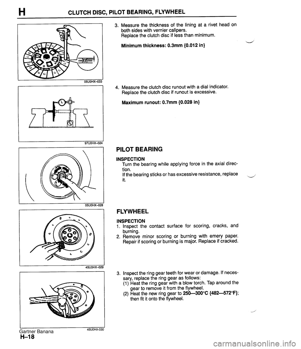
H CLUTCH DISC, PILOT BEARING, FLYWHEEL 3. Measure the thickness of the lining at a rivet head on both sides with vernier calipers. Replace the clutch disc if less than minimum. Minimum thickness: 0.3mm (0.012 in) 4. Measure the clutch disc runout with a dial indicator. Replace the clutch disc if runout is excessive. Maximum runout: 0.7mm (0.028 in) PILOT BEARING INSPECTION Turn the bearing while applying force in the axial direc- tion. If the bearing sticks or has excessive resistance, replace it. FLYWHEEL INSPECTION 1. lnspect the contact surface for scoring, cracks, and burning. 2. Remove minor scoring or burning with emery paper. Repair if scoring or burning is major. Replace if cracked. 3. lnspect the ring gear teeth for wear or damage. If neces- sary, replace the ring gear as follows: (1) Heat the ring gear with a blow torch. Tap around the gear to remove it from the flywheel. (2) Heat the new ring gear to 250--300°C (482--572°F); then fit it onto the flywheel. Gartner Banana
Page 361 of 1708

TROUBLESHOOTING GUIDE J TROUBLESHOOTING GUIDE Problem ~bnormal noise lumps out of gear libration Possible Cause nsufficient oil leterioration of oil quality Norn bearing Norn contact surface of countershaft gear Norn contact surface of gears Excessive gear backlash larnaged gear teeth nsufficient oil leterioration of oil quality Worn synchronizer ring Worn synchronizer cone of gear Poor contact of synchronizer ring and gear cone Excessive longitudinal play of gears Worn bearing Improper disengagement of clutch Weak detent ball spring Worn shift fork Worn clutch hub Worn clutch hub sleeve Worn gears Excessive gear backlash Worn bearing Incorrect installation or looseness of power plant frame Action 4dd oil 3eplace with specified )il qeplace 4dd oil 3eplace with specified ~il Replace Replace Replace Replace Replace Repair or replace Replace Replace Replace Replace Replace Replace Replace Correct or tighten Page 5-8 J-8 J-9 J-16 5-1 6,19,20 J-16,19,20 J-16,19,20 J-8 J-8 J-16,19 J-16,19 J-16, 19 J-l6,19,20 J-9 section H J-15 J-15 J-16,19 J-16,19 J-16, 19,20 J-l6,19,20 J-9 J-45 35UOJX-O( Gartner Banana
Page 363 of 1708
TRANSMISSION J TRANSMISSION 49 0839 425C Puller set, bearing For removal of bearing For installation of bearing Installer, bearing For removal of clutch hub assembly For holding mainshaft Puller, fan pulley boss Holder, mainshaft For removal of locknut 49 0862 350 Guide, shift fork / For installation of interlock pin Wrench, mainshaft locknut 49 HOl7 101 Hook For removal of bearing 49 071 0 520 Puller, bearing For removal of bearing For removal of transmission case For installation of bearing Pusher, main drive shaft \-4 I Installer, bearing 49 F401 330B Installer set, bearing For installation of bearing For installation of spring and ball Guide, interlock <-- pin For installation of clutch hub assembly 49 8025 OAO Installer, oil seal For installation of dust seal For installation of oil seal 49 6025 001 Body (Part of 49 6025 OAO) For installation of oil seal Handle (Part of 49 8025 OAO) Gartner Banana