Page 1078 of 1708
u HEATER HEATER UNIT Removal / Installation 1. Remove the dashboard. (Refer to section S.) 2. Remove the heater unit as shown in the figure. 3. Install in the reverse order of removal. 7.9-10.7 Nm (80-110 kgfcm, 69.5--95.4 In+bf] 1. Heater hose U-16 45UOUX4 2. Heater unit Gartner Banana
Page 1080 of 1708
u HEATER BLOWER UNIT Removal / Installation 1. Remove the glove compartment. (Refer to section S.) 2. Remove the blower unit as shown in the figure. 3. Install in the reverse order of removal. 7.910.7 Nm (80-110 kof cm, 69.5-95.4 Inlbf) 1. Blower unit U-18 Gartner Banana
Page 1091 of 1708

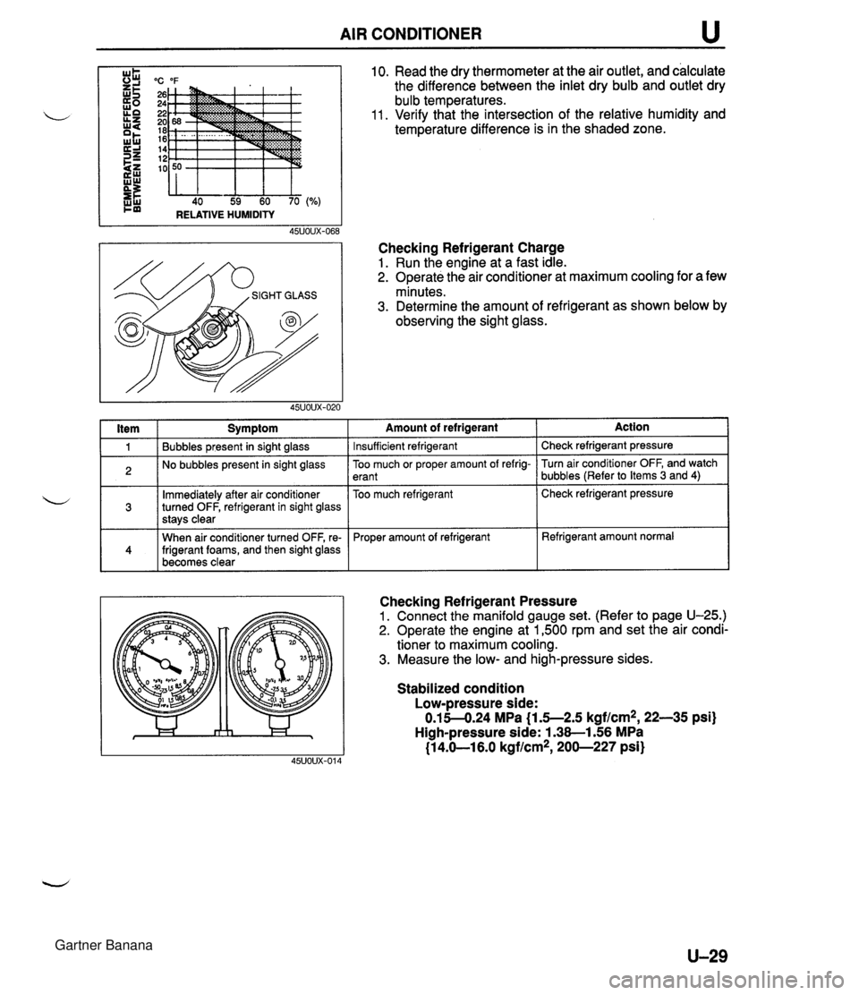
AIR CONDITIONER u "C "F 26 24 22 20 18 16 14 12 10 40 59 60 70 RELATIVE HUMIDITY I ltem I Symptom 10. Read the dry thermometer at the air outlet, and calculate the difference between the inlet dry bulb and outlet dry bulb temperatures. 11. Verify that the intersection of the relative humidity and temperature difference is in the shaded zone. Checking Refrigerant Charge 1. Run the engine at a fast idle. 2. Operate the air conditioner at maximum cooling for a few minutes. 3. Determine the amount of refrigerant as shown below by observing the sight glass. 1 Bubbles present in sight glass 2 No bubbles present in sight glass Immediately after air conditioner turned OFF, refrigerant in sight glass stavs clear 141 When air conditioner turned OFF, re- frigerant foams, and then sight glass becomes clear -- Amount of refrigerant Insufficient refrigerant Action Check refrigerant pressure -- Too much or proper amount of refrig- erant Too much refrigerant Checking Refrigerant Pressure 1. Connect the manifold gauge set. (Refer to page U-25.) 2. Operate the engine at 1,500 rpm and set the air condi- tioner to maximum cooling. 3. Measure the low- and high-pressure sides. Turn air conditioner OFF, and watch bubbles (Refer to Items 3 and 4) Check refrigerant pressure Proper amount of refrigerant Stabilized condition Low-pressure side: 0.15-4.24 MPa {I .5--2.5 kgf/cm2, 22-35 psi) High-pressure side: 1.38-1.56 MPa (1 4.61 6.0 kgflcm*, 200-227 psi) Refrigerant amount normal Gartner Banana
Page 1092 of 1708
u AIR CONDITIONER COOLING UNIT Removal 1 Installation 1. Discharge the refrigerant system. 2. Remove the glove compartment. (Refer to section S.) il 3. Remove in the order shown in the figure. Immediately plug all open fittings to keep moisture out of the system. 4. Install in the reverse order of removal. Position the unit so that its connections match those of the heater unit and blower unit. Apply clean compressor oil to the O-rings before connecting the fittings; do not ap- ply compressor oil to the fitting nuts. Tightening torque Inlet pipe: 10-19 N-m (1.0-2.0 kgfsm, 8-14 ft-lbf} Outlet pipe: 20-29 N-m (2.0-3.0 kgf-m, 15--21 ft-lbf} 5. Charge the refrigerant system. (Refer to page U-25.) 7.910.7 N.m {EO-110 kgfmn, 69.5-95.4 In4bf} 45uoux-071 1. Cooling unit 2. Sealing plate Disassembly / Assembly . . . . . . page U-31 U-30 Gartner Banana
Page 1094 of 1708

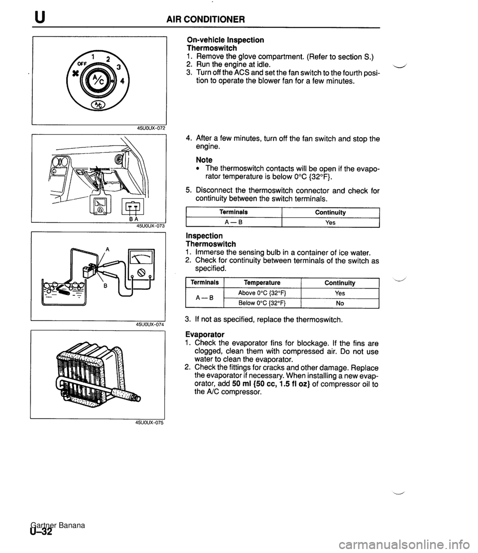
AIR CONDITIONER On-vehicle Inspection Thermoswitch 1. Remove the glove compartment. (Refer to section S.) 2. Run the engine at idle. u 3. Turn off the ACS and set the fan switch to the fourth posi- tion to operate the blower fan for a few minutes. 4. After a few minutes, turn off the fan switch and stop the engine. Note The thermoswitch contacts will be open if the evapo- rator temperature is below 0°C (32°F). 5. Disconnect the thermoswitch connector and check for continuity between the switch terminals. I Terminals I Continuity I I A-B I Yes I - -- Inspection Thermoswitch 1. Immerse the sensing bulb in a container of ice water. 2. Check for continuity between terminals of the switch as specified. 3. If not as specified, replace the thermoswitch. Continuity ( Terminals I Temperature A-B Evaporator 1. Check the evaporator fins for blockage. If the fins are clogged, clean them with compressed air. Do not use water to clean the evaporator. 2. Check the fittings for cracks and other damage. Replace the evaporator if necessary. When installing a new evap- orator, add 50 ml (50 cc, 1.5 fl oz) of compressor oil to the A/C compressor. d Above 0°C {32OFj Below 0°C (32°F) Yes No Gartner Banana
Page 1120 of 1708

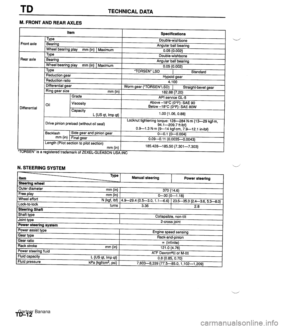
TECHNICAL DATA --- M. FRONT AND REAR AXLES Specifications TY pe Bearing Angular ball bearing 0.05 10.002) Front axle Rear axle - Wheel bearing play mm {in) I Maximum Bearina Anaular ball bearina . .. Wheel bearina plav mm {in) I Maximum " " 0.05 {0.002) 'TORSEN" LSD I Standard TY pe Reduction aear Hvpoid sear Reduction ratio Differential aear 4.100 Worm near ("1ORSEN"LSD) I Straiaht-bevel gear - - Ring gear size mm {in) 1 Grade 182.88 17.201 API service GL-5 Oil 1 Viscosity Above -18°C {O°F): SAE 90 Below -18°C {O°F): SAE 80W Differential Capacity L {US at. Imp at) Locknut tightening torque: 128-284 N.m {I 3-29 kgf.m, 94.1-209.7 ft.lbf) Drive pinion preload (without oil seal) TORSEN" is a Backlash mm {in) . , egistered trademark of ZEXEL-GLEASON US, Side gear and pinion gear Final gear , INC Length (Pilot section to pilot section) mm (in N. STEERING SYSTEM Steering wheel Outer diameter mm {in} 1 370 11 4.6) Type item Free play mm {in) I 630 {O-1.18) Wheel effort N (kaf, Ibfl 14.9--29.4{0.5--3.0, 1.1-4.6) 123.545.3 12.A4.6,5.3--8.0) turns I 3.36 1 2.8 I 1 Manual steering Steering Shaft Shaft type I Collapsible, non-tilt Power steering Joint type I 2-cross joint Power steering system Gear ratio 1 m (infinite) Rack stroke rnm {in) I 121 .O 14.76) Power assist type Engine speed sensing Power steering fluid Fluid capacity L {US qt, Imp qt} Fluid pressure kPa {kgf/cm2, psi) Gear type - - ATF DexrongII oi M-111 0.8 {0.85,0.70) 7,603--8,339 (77.5850, 1 ,I 02-1,209) Rack-and-pinion Gartner Banana
Page 1255 of 1708
u GENERAL SERVICE INFORMATION INSTALLATION PREPARATIONS Application of weld-through primer 1 For treatment against cor- rosion, remove paint, grease, and other material from tl ,portion of the new part and body to be welded, and apply weld- Determination of welding method If the total thickness at the area to be welded is 3mm (0.12 in) or more, use a drill to make holes of about 07 for plug welding, then use a CO2 gas shielded-arc welder to make the plug welds. Note Do not attempt to spot weld sections over 3mm (0.12 in) thick, as the weld strength would be too low. or less Making holes for plug-welding Rough cutting of new parts For places that cannot be spot welded, make For cut-and-join areas, allow for an overlap of a hole of 05-06 (at the new part of the body 30-50mm (1.18-1.97 in) and then roughly cut side) using a punch or drill. the new part, using a hand saw or air saw as necessary. 30-50mm (1.18-1.97 in) (1.18-1.97 in) overlap Gartner Banana
Page 1257 of 1708
GENERAL SERVICE INFORMATION L ANTI-CORROSION TREATMENT When replacing body panels, always apply body sealer, anti-rust treatment. or undercoating ac- cording to the requirements of the market. Application of surface agent and body sealer After first applying the coating of surfacing agent, apply body sealer where necessary. Note For locations where application of body sealer is difficult after installation, apply .t-before the installation. Application of rust inhibitor Undercoating Apply rust inhibitor to the back of welded areas, Use antirust treatment for underbody welding using an installation hole or a gap near that spots and wheel housings. section. Gartner Banana