1994 MAZDA MX-5 SECTION T
[x] Cancel search: SECTION TPage 942 of 1708

CRUISE CONTROL SYSTEM B+: Battery Dositive voltage erminall Win color . . .. Action Connected to Cruise actuator Cruise actuator Test condition Main switch OFF Main switch ON Cruise A\actuator Specification Main switch OFF Main switch ON PCMT OV 9V Main switch OFF . Main switch ON Brake switch Go to Step 8 OV . 9V Ignition switch OFF lanition switch ON ParklNeutral switch Cruise control Main switch ON switch (Set switch and coast switch) Check main switch OV 9V - Brake pedal depressed Brake ~edal released Clutch switch Check main switch OV B+ Shift to "N" or "P" range Shift to other ranae Go to section K OV 9V Clutch pedal depressed Clutch pedal released Stoplight switch Go to Step 4 OV 5V Cruise control switch (Resume switch and accel switch) speed I While rotating rear tires I beMeenM,, sor Run I GO to Step 9 Go to section K OV B+ Brake pedal depressed Brake pedal released Cruise actuator I I I Battery 1 Constant I B+ I Repair wiring harness Go to Step 5 Main switch ON While turning resume switch after main switch ON B+ OV Main switch OFF Step 4 - Inspection of brake switch 1. Disconnect the brake switch connector. 2. Check for continuity between terminals of the switch. Go to Step 7 B+ OV OV GND 1 Constant Pedal position Go to Step 6 OV I Repair wiring harness Terminal A B 1 I Main switch ON 9V 45UOTX-19 Go to Step 8 3. If not as specified, replace the brake switch. 4. If the switch is OK, repair the wiring harness (fuse - brake switch - control unit). Pedal released Pedal depressed M: Continuity 0 0 Gartner Banana
Page 947 of 1708

T 2 CRUISE CONTROL SYSTEM PRESS 45UOTX-209 Inspection Procedure Quick inspection 1. Connect a 1.4W test light between terminals D and F, of the cruise control unit connector. u Note There is no wire in terminal D of the connector. Push the test light through the connector and touch the cor- responding pin on the control unit. 2. Turn the ignition switch to ON. 3. Shift the selector lever to D or R range. 4. Verify that the MAlN switch is off. (The MAlN indicator light will be off .) 5. Turn the RESUMEIACCEL switch and the MAlN switch simultaneously to activate the system inspection. The MAlN indicator light will come on. 6. Operate each switch as described below and obtain the problem code numbers. Note The cruise control system will not operate in self-diag- nosis mode. 7. After retrieving the code(s), press the MAlN switch to deactivate the system inspection. The MAlN indicator light will go off. 8. Follow the action corresponding to the problem code. --, Service Code Table Press SETICOAST switch Procedure Press RESUMEIACCEL switch Pattern of output signal (Test light) ON OFF nn M nn Depress brake pedal ON OFF ON Drive vehicle above 40 km/h (25 MPH) Turn ignition switch to ON and shift the selector lever to P or N range (For AT) Depress clutch pedal (For MT) Code No. oN OFF Action lnspect cruise control switch (Refer to page T-106) lnspect cruise control switch (Refer to page T-106) lnspect stoplight switches (Refer to pages T-105 and T-56) lnspect parwneutral switch (Refer to section K) or clutch switch (Refer to page T-105) lnspect vehicle speed sensor or wire harness (Refer to page T-106) Gartner Banana
Page 948 of 1708

CRUISE CONTROL SYSTEM T T P N L JHF B T P N L JHF B CRUISE CONTROL UNIT Removal 1. Remove the passenger side kick panel. 2. Remove the nut and the control unit. Installation Install in the reverse order of removal. Inspection 1. Check the terminal voltages of the control unit. Discon- nect the CIS control unit connector before measuring the voltage at terminal J. 2. If the terminal voltages are correct, replace the control unit. B+: Battery positive voltage berminail Wire color I Connected to I Test condition 1~~ecificationl Action A B C E F (GN) ' (GIB) (G/O) (R) (YIB) G H PCMT (LGIB) J Cruise actuator Cruise actuator Cruise actuator Main switch Main switch (Y) Ignition switch OFF lanition switch ON Main switch OFF Main switch ON Main switch OFF Main switch ON Main switch OFF Main switch ON Main switch OFF Main switch ON Main switch OFF Main switch ON Brake switch (BIL) (BWW) OV B+ Shift to "N" or "P" range Shift to other range Clutch pedal depressed Clutch pedal released ParkINeutral switch Clutch switch OV 9V OV 9V ov 9V B+ OV OV B+ Check AT control unit (Refer to section K) - Brake pedal depressed Brake pedal released Check cruise actuator (Refer to page T-107) Check main switch (Refer to page T-106) OV 5V OV B+ OV 9V Check parWneutral switch (Refer to section K) Check clutch switch (Refer to page T-105) Check brake switch (Refer to page T-105) Gartner Banana
Page 959 of 1708

AUDIO Cassette tape player Name Tape slot Playlreverse button Stopleject button APC (automatic program control) button Dolby noise reduction bunon*' Fast forwardlrewind button lllustration Operation Insert a tape into tape slot to begin tape operation When tape is inserted, system determines tape type by identification hole in cassette pack; if metal or chromium tape, METAL is shown on display Press button during tape playback to play reverse side of tape Press button during fast forwardlrewind mode to play tape Press button during modes other than tape playback or tape Player OFF to select tape mode and play tape Press button during fast forwardlrewind mode to cancel mode; select tape playback mode, if desired Press button during tape playback to stop play Press again to eject tape Press button during tape playback and APC appears on display In this condition, press FF button skip to beginning of next program Press REW button during tape playback to rewind tape to beginning of current tune APC detects silence of more than 15 seconds and skips forward to next recorded section Press button when playing tape encoded with Dolby NR Dolby alternately turns ONIOFF with each press Press REW button to rewind tape Press FF button to fast forward tape The Dolby noise reduction system is manufactured under license of the Dolby Laboratory Licensing Corporation. -,, DOLBY and 00 are registered trade marks of Dolby Laboratory Licensing Corporation. Compact disc (CD) player Caution Never use mini CDs (8 cm (3.1 in)) because they may dislodge from the adapter and damage the disc or player. Use only standard CDs (12 cm (4.7 in)). Name Illustration Disc slot Playlstop button Lightly push disc, label-side up, into slot; auto loading mechanism will take over to set disc and begin play During loading, DlSC SET flashes on display When loading completed, DlSC SET displayed Press this button while disc is being played and play will pause Press again and play will resume Press button during tape or radio mode to play loaded disc Press button to eject disc Disc SET flashes on display Press again and disc is reloaded Gartner Banana
Page 962 of 1708

AUDIO T Cassette Player Tape slot Name APC (automatic program control) button Illustration U~ldown button I Tape button Playlreverse button Tape eject button 7 Dolby noise reduction button 'I -- - Operation Insert a tape into tape slot to automatically begin tape operation When tape is inserted, system determines tape type by identification hole in cassette pack; if metal or chromium tape, METAL is shown on display Press button during tape playback to enter APC mode; APC appears on display In this mode, press ( A ) button to skip to beginning of next program Press (V ) button during tape playback to rewind tape to beginning of current tune When APC detects silence of more than 15 seconds, it automatically skips forward to next recorded section Press (V ) button to rewind tape; press button again to play tape Press (A ) button to fast forward tape; press button again to play tape Press button during fast forward/rewind mode to cancel mode Press button to begin play Press button during tape playback to play reverse side of tape Press button to eject cassette tape Press button when playing tape encoded with Dolby NR Dolby alternately turns on or off with each press *l The Dolby noise reduction system is manufactured under license of the Dolby Laboratory Licensing Corporation. DOLBY and 00 are registered trade marks of Dolby Laboratory Licensing Corporation. Gartner Banana
Page 1063 of 1708

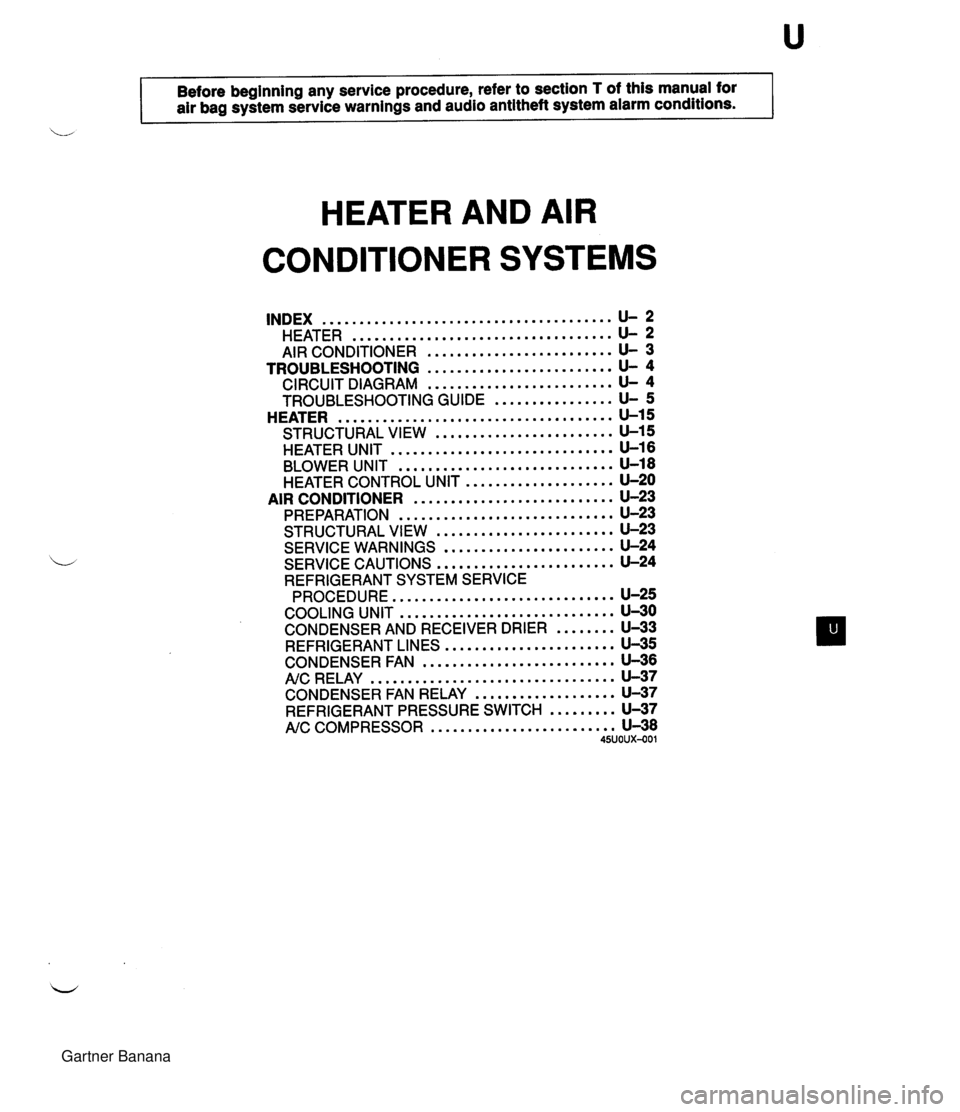
Before beginning any service procedure. refer to section T of this manual for I air bag system service warnings and audio antitheft system alarm conditions . HEATER AND AIR CONDITIONER SYSTEMS ....................................... INDEX U- 2 ................................... HEATER U- 2 AIR CONDITIONER ......................... U- 3 TROUBLESHOOTING ......................... U- 4 CIRCUIT DIAGRAM ......................... U- 4 TROUBLESHOOTING GUIDE ................ U- 5 ..................................... HEATER U-15 ........................ STRUCTURAL VIEW U-15 HEATER UNIT .............................. U-16 BLOWER UNIT ............................. U-18 HEATER CONTROL UNIT .................... U-20 AIR CONDITIONER ........................... U-23 PREPARATION ............................. U-23 STRUCTURAL Vl EW ........................ U-23 SERVICE WARNINGS ....................... U-24 SERVICE CAUTIONS ........................ U-24 REFRIGERANT SYSTEM SERVICE PROCEDURE .............................. U-25 COOLING UNIT ............................. U-30 CONDENSER AND RECEIVER DRIER ........ U-33 REFRIGERANT LINES ....................... U-35 CONDENSER FAN .......................... U-36 AIC RELAY ................................. U-37 ................... CONDENSER FAN RELAY U-37 REFRIGERANT PRESSURE SWITCH ......... U-37 NC COMPRESSOR ......................... U-38 45U0Ux-001 Gartner Banana
Page 1069 of 1708

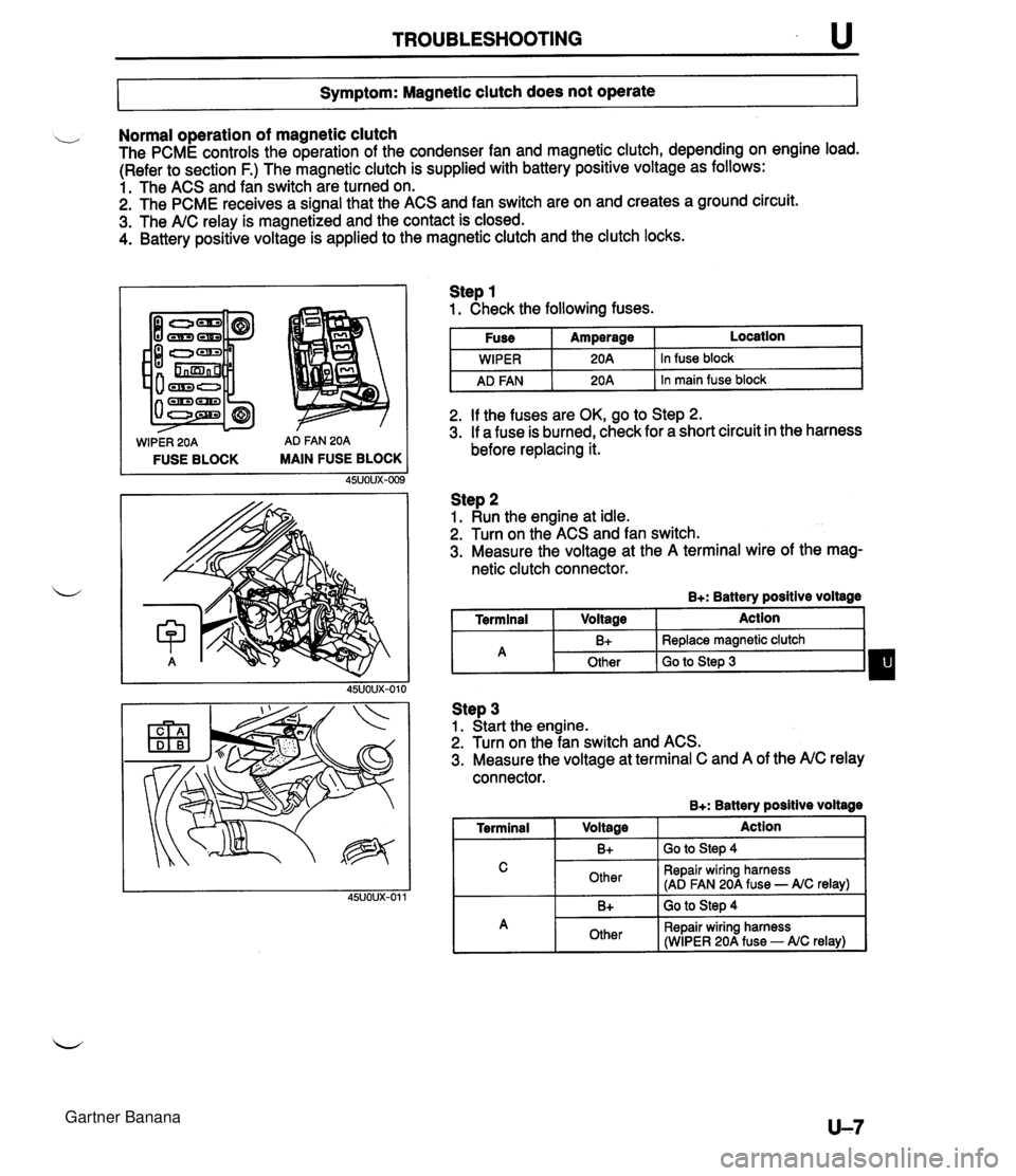
TROUBLESHOOTING u 7- Symptom: Magnetic clutch does not operate I Normal operation of magnetic clutch The PCME controls the operation of the condenser fan and magnetic clutch, depending on engine load. (Refer to section F.) The magnetic clutch is supplied with battery positive voltage as follows: 1. The ACS and fan switch are turned on. 2. The PCME receives a signal that the ACS and fan switch are on and creates a ground circuit. 3. The A/C relay is magnetized and the contact is closed. 4. Battery positive voltage is applied to the magnetic clutch and the clutch locks. WIPER 20A AD FAN 20A FUSE BLOCK MAIN FUSE BLOCK Step 1 1. Check the following fuses. I Fuse I Amperage I Location I I I . - I WIPER I 20A 1 In fuse block I I AD FAN I 20A 1 In main fuse block I 2. If the fuses are OK, go to Step 2. 3. If a fuse is burned, check for a short circuit in the harness before replacing it. Step 2 1. Run the engine at idle. 2. Turn on the ACS and fan switch. 3. Measure the voltage at the A terminal wire of the mag- netic clutch connector. B+: Battery positive voltage I Terminal I Voltage I Action 1 Step 3 1. Start the engine. 2. Turn on the fan switch and ACS. 3. Measure the voltage at terminal C and A of the A/C relay connector. B+: Batterv positive voltaae - -- A 1 Terminal I V0lta0e 1 Action I I C I Other I Repair wiring harness (AD FAN 20A fuse - AIC relay) I B+ Other I 1. -. B+ I GO to step 4 Replace magnetic clutch Go to Step 3 I A 1 Other I Repair wiring harness (WIPER 20A fuse - AIC relay) I Gartner Banana
Page 1071 of 1708

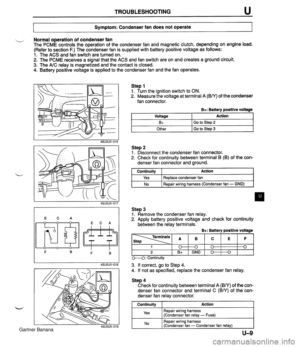
TROUBLESHOOTING u Symptom: Condenser fan does not operate Normal operation of condenser fan The PCME controls the operation of the condenser fan and magnetic clutch, depending on engine load. (Refer to section F.) The condenser fan is supplied with battery positive voltage as follows: 1. The ACS and fan switch are turned on. 2. The PCME receives a signal that the ACS and fan switch are on and creates a ground circuit. 3. The A/C relay is magnetized and the contact is closed. 4. Battery positive voltage is applied to the condenser fan and the fan operates. Step 1 1. Turn the ignition switch to ON. 2. Measure the voltage at terminal A (B/Y) of the condenser fan connector. B+: Battery positive voltage Step 2 1. Disconnect the condenser fan connector. 2. Check for continuity between terminal B (B) of the con- denser fan connector and ground. Voltage B+ Other I GO to step 3 Action Go to Step 2 I continuity I Action I Step 3 1. Remove the condenser fan relay. 2. Apply battery positive voltage and check for continuity between the relay terminals. B+: Battery positive voltage Yes No Replace condenser fan Repair wiring harness (Condenser fan - GND) M: Continuity - - - 3. If correct, go to Step 4. 4. If not as specified, replace the condenser fan relay. 1 0 2 B+ Step 4 Check for continuity between terminal A (BN) of the con- denser fan connector and terminal C (BN) of the con- denser fan relay connector. I Continuity I Action 1 Repair wiring harness (Condenser fan relay - Fuse) B 0 GND I Repair wiring harness (Condenser fan - Condenser fan relay) I C 0 0 E 0 F 0 Gartner Banana