Page 1008 of 1708

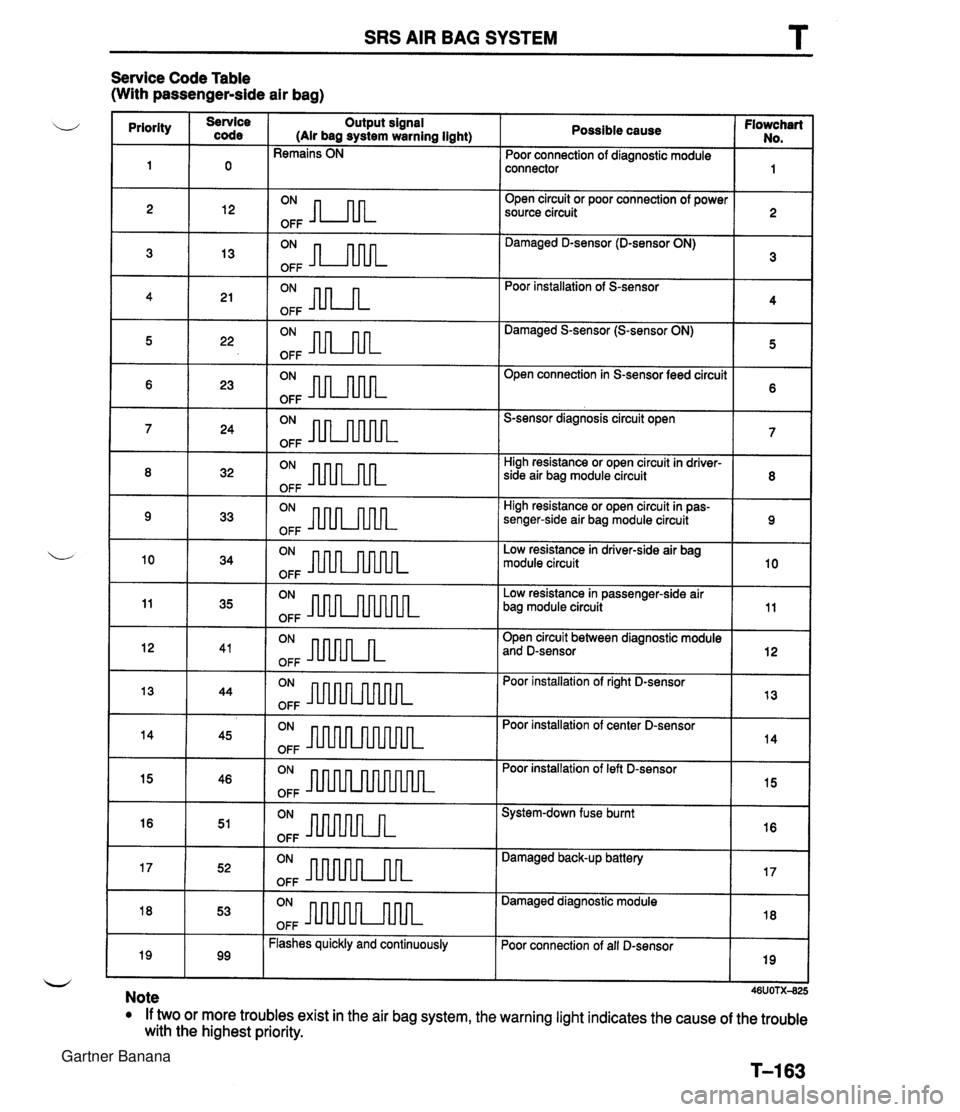
SRS AIR BAG SYSTEM T Service Code Table (With passenger-side air bag) Possible cause Flowchart No. Poor connection of diagnostic module priority connector Open circuit or poor connection of power source circuit code Output signal (Air bag system warning light) Remains ON Damaged D-sensor (D-sensor ON) 2 Poor installation of S-sensor Damaged S-sensor (S-sensor ON) 12 5 22 OFF OFF Open connection in S-sensor feed circuit S-sensor diagnosis circuit open High resistance or open circuit in driver- 8 32 OFF side air bag module circuit High resistance or open circuit in pas- senger-side air bag module circuit Low resistance in driver-side air bag module circuit I 11 1 35 ION- OFF b Low resistance in passenger-side air bag module circuit Open circuit between diagnostic module 10 and D-sensor - Poor installation of right D-sensor 113 144 ION- OFF 34 OFF Poor installation of center D-sensor 14 I 15 1 46 ION- OFF Poor installation of left D-sensor 45 System-down fuse burnt OFF 1 17 1 52 ( ON ml flk OFF Damaged back-up battery Damaged diagnostic module I 18 I 53 IoNm[~ OFF Poor connection of all D-sensor 19 I I I w Note If two or more troubles exist in the air bag system, the warning light indicates the cause of the trouble with the highest priority. T-163 99 Flashes quickly and continuously Gartner Banana
Page 1009 of 1708
T SRS AIR BAG SYSTEM I Flowchart No1 I Symptom I Air bag warning light remains ON I Possible cause Poor connection of diagnostic module connector Defective diagnostic module 0 Defective wiring harness CONNECTOR Step 1 Carry out "Before Servicing" procedure under GENER- AL PROCEDURES, page T-160. Step 2 1. Verify that the diagnostic module connector is securely connected to the diagnostic module. 2. Verify that the shorting bar is in the fully retracted posi- tion. 3. If the connector and shorting bar are OK, go to step 3. Step 3 1. Disconnect the diagnostic module connector. 2. Remove the shorting bar from the diagnostic module connector. 3. Check the air bag system warning light. I Llght condltlon 1 Action I I I Illuminate I Repair wiring harness (Instrument cluster - Diagnostic module) I Not illuminate Replace diagnostic module (Refer to page T-208) Gartner Banana
Page 1033 of 1708
Possible cause u 0 Burnt air bag warning light bulb Defective diagnostic module Defective wiring harness Step 1 Carry out "Before Servicing" procedure under GEN- ERAL PROCEDURES, page T-1 60. Air bag system warning light does not illuminate for 6 seconds Flowchart No.1 Step 2 1. Disconnect the diagnostic module connector. 2. Turn the ignition switch to ON. 3. Check the air bag warning light. I Llght condition I Action 1 Symptom 1 Illuminate I Replace diagnostic module (Refer to ~aae T-208) 1 -- I Not illuminate I GO to step 3 J Step 3 1. Remove the instrument cluster. 2. Check the air bag system warning light bulb. I Repair wiring harness (Diagnostic module--Instrument cluster) I Bulb Burnt Action Replace bulb .- Gartner Banana
Page 1034 of 1708
SRS AIR BAG SYSTEM T u Possible cause Poor connection of diagnostic module connector Defective diagnostic module Defective wiring harness Step 1 Carry out "Before Servicing" procedure under GEN- ERAL PROCEDURES, page T-1 60. Air bag warning light remains ON Flowchart No.2 Step 2 1. Verify that the diagnostic module connector is securely connected to the diagnostic module. 2. Verify that the shorting bar is in the fully retracted posi- tion. 3. If the connector and shorting bar are OK, go to step 3. Symptom Step 3 1. Disconnect the diagnostic module connector. 2. Remove the shorting bar from the diagnostic module connector. 3. Check the air bag warning light. Light condition I Action I Illuminate Repair wiring harness (Diagnostic modul~lnstrument duster) I Not illuminate 1 Replace diagnostic module (Refer to Dacie T-208) Gartner Banana
Page 1061 of 1708

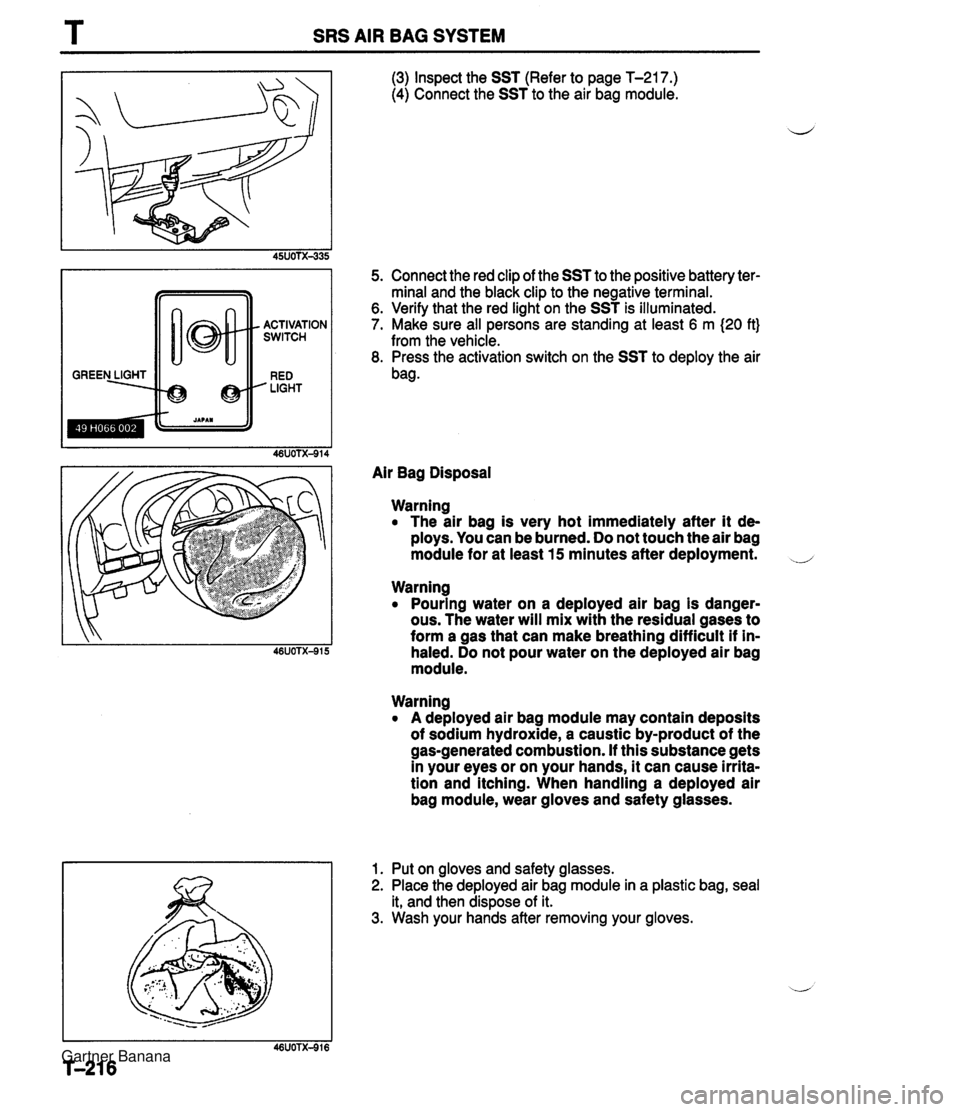
T SRS AIR BAG SYSTEM GREEN LIGHT -+@ @ . ACTIVATION SWITCH RED ' LIGHT (3) Inspect the SST (Refer to page T-217.) (4) Connect the SST to the air bag module. 5. Connect the red clip of the SST to the positive battery ter- minal and the black clip to the negative terminal. 6. Verify that the red light on the SST is illuminated. 7. Make sure all persons are standing at least 6 m (20 ft} from the vehicle. 8. Press the activation switch on the SST to deploy the air bag. Air Bag Disposal Warning The air bag is very hot immediately after it de- ploys. You can be burned. Do not touch the air bag module for at least 15 minutes after deployment. Warning Pouring water on a deployed air bag is danger- ous. The water will mix with the residual gases to form a gas that can make breathing difficult if in- haled. Do not pour water on the deployed air bag module. Warning A deployed air bag module may contain deposits of sodium hydroxide, a caustic by-product of the gas-generated combustion. If this substance gets in your eyes or on your hands, it can cause irrita- tion and itching. When handling a deployed air bag module, wear gloves and safety glasses. 1. Put on gloves and safety glasses. 2. Place the deployed air bag module in a plastic bag, seal it, and then dispose of it. 3. Wash your hands after removing your gloves. Gartner Banana
Page 1123 of 1708

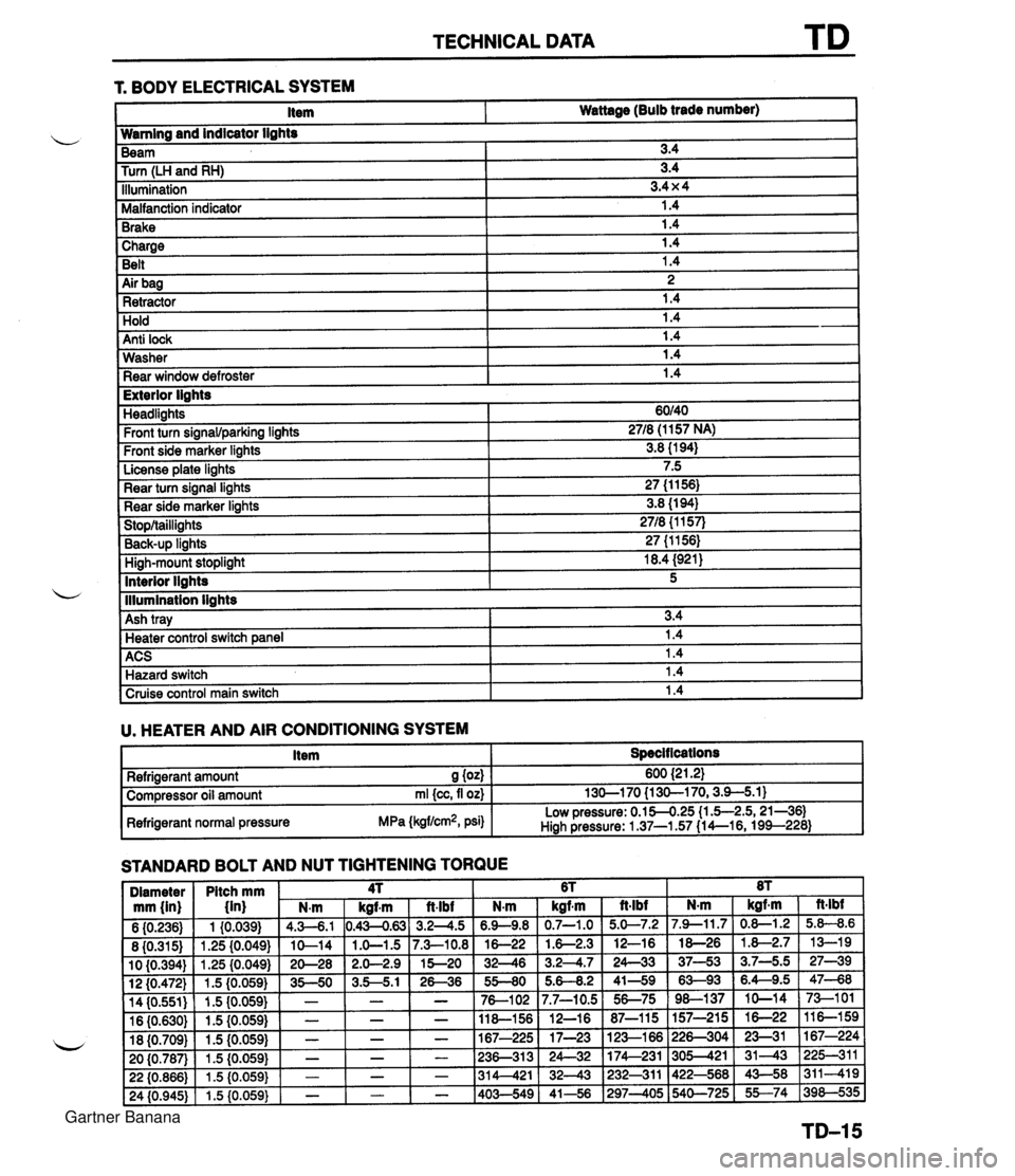
TECHNICAL DATA 1 Charge I 1.4 Belt 1.4 r. BODY ELECTRICAL SYSTEM 1 Air bag I 2 1 Retractor 1.4 Item Wattage (Bulb trade number) Hold Anti lock Wamlng and indicator lights 1.4 1.4 Washer Rear window defroster Beam Turn (LH and RH) Illumination Malfanction indicator Brake 1.4 1.4 I Exterior lights 3.4 3.4 3.4 x 4 1.4 1.4 Headlights Front turn signawparking lights Front side marker lights License plate lights Rear turn signal lights Rear side marker lights Stop/taillights Back-UP linhts High-mount stoplight I 18.4 (921) ACS 1 1.4 Hazard switch 1.4 60140 2718 (1 157 NA) 3.8 (1 94) 7.5 27 (1 1 56) 3.8 (1 94) 2718 {I 157) 27 (1 1561 Interior llahts - I lllumination lights I Cruise control main switch I 1.4 I 5 Ash tray U. HEATER AND AIR CONDITIONING SYSTEM I Item I Specit lcations I 3.4 Heater control switch ane el I 1.4 STANDARD BOLT AND NUT TIGHTENING TORQUE Refrigerant amount S (04 Compressor oil amount rnl {cc, fl oz) Refrigerant normal pressure MPa (kgflcm2, psi) 600 {2 1.21 130-1 70 {I 30-1 70,3.9-5.1) Low pressure: 0.154.25 (1 .5-2.5,21-361 Hiah Pressure: 1 37-1.57 (1 4--16, 199--228) Gartner Banana
Page 1275 of 1708
CONSTRUCTION No. 0 Part Name Bumper bracket Hood (Bonnet) 1 8 / Front frame, upper rear Crossmember No. 1 Shroud panel assy Radiator bracket No. @ Dash side junction I @ / Front frame, rear Part Name Crossmember No. 2 @ @I @ Light lid Dash panel assy Seat bracket No. 3 gusset Front frame, upper front Dash panel assy I @ / Stabilizer bracket @ @I Cowl panel, front Instrument bracket Apron reinforcement Front wheel apron assy I @ I Front wheel apron panel Q Tie-down hook reinforcement Front floor side pan Tunnel side junction Front frame @ @ Front fender panel Torque box Gartner Banana
Page 1277 of 1708

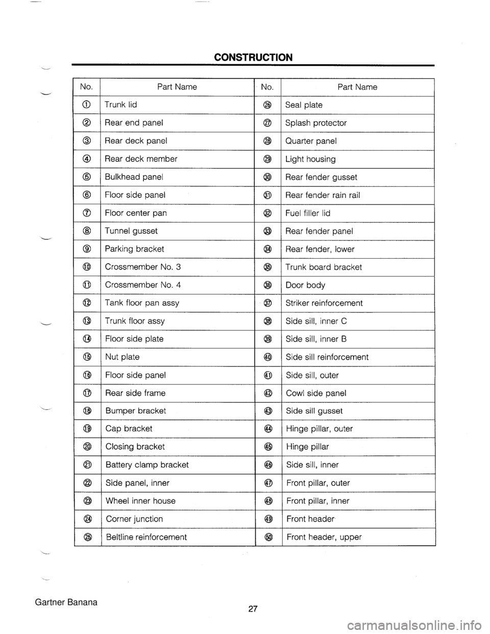
CONSTRUCTION No. @ I Rear deck panel @ @ - - 1 8 1 Quarter panel Part Name @ I Rear deck member Trunk lid Rear end panel I @ 1 Light housing No. Part Name @ Q @ I Tunnel gusset Seal plate Splash protector @ @ I @ I Rear fender panel Bulkhead panel Floor side panel Floor center pan 0 I Crossmember No. 4 @ @ I @ I Door body @ Q Rear fender gusset Rear fender rain rail Fuel filler lid Parking bracket Crossmember No. 3 8 1 Floor side plate @ @ I @ / Side sill, inner B @ @ I ~ut plate Rear fender, lower Trunk board bracket Tank floor pan assy Trunk floor assy 1 8 1 Side sill reinforcement Q @ 0 I Rear side frame Striker reinforcement Side sill, inner C I I I 1 8 ( Cowl side panel @ @ I Closing bracket I @ I Hinge pillar Floor side panel @ @ 8 1 Battery clamp bracket I @ I Side sill, inner Side sill, outer Bumper bracket Cap bracket @ I Corner junction 1 8 1 Front header, Q @ @ @ Side sill gusset Hinge pillar, outer Side panel, inner Wheel inner house @ @ @ Beltline reinforcement Front pillar, outer Front pillar, inner @ Front header, upper Gartner Banana