Page 256 of 1708
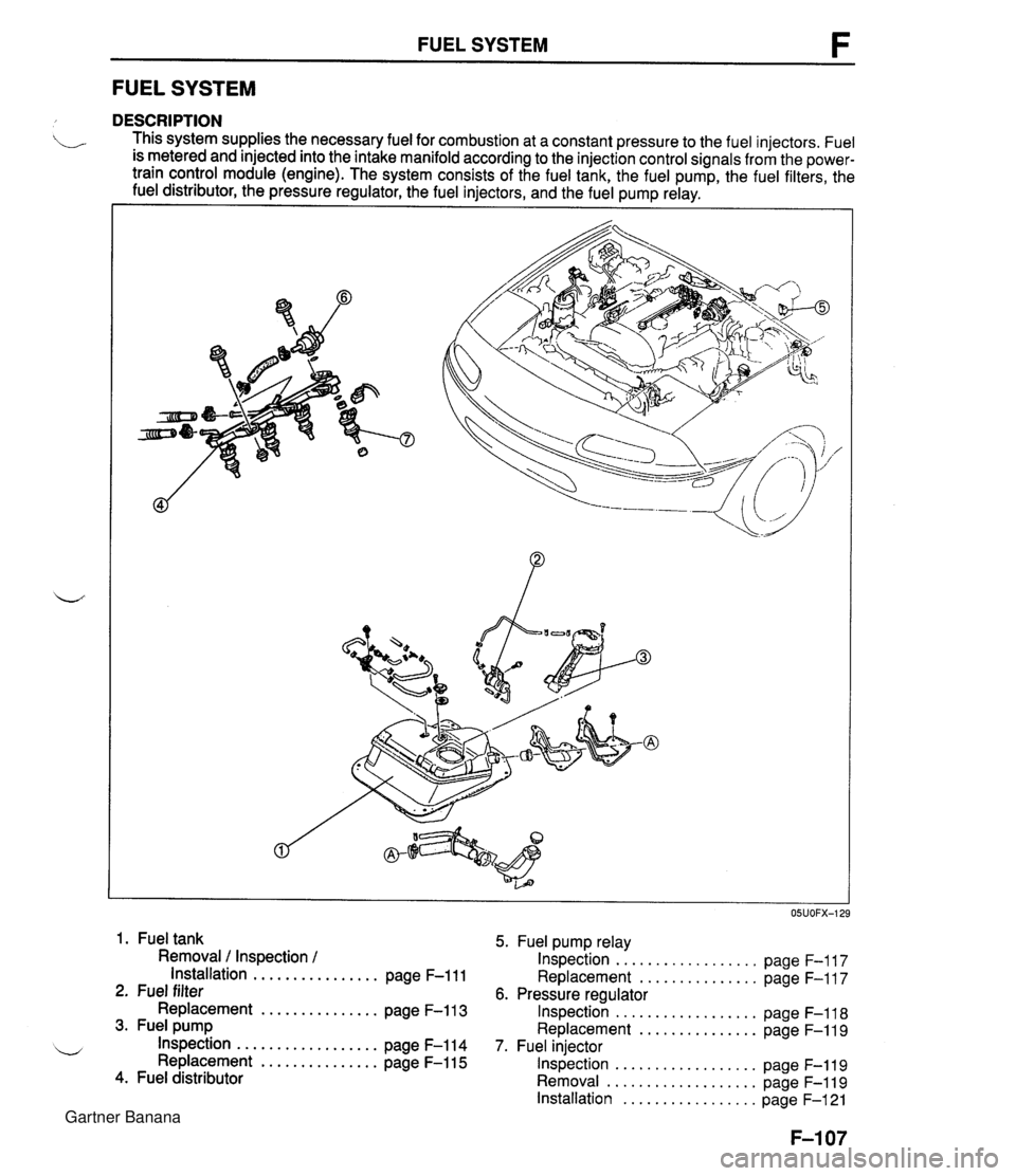
FUEL SYSTEM F FUEL SYSTEM DESCRIPTION . This system supplies the necessary fuel for combustion at a constant pressure to the fuel injectors. Fuel is metered and injected into the intake manifold according to the injection control signals from the power- train control module (engine). The system consists of the fuel tank, the fuel pump, the fuel filters, the fuel distributor, the pressure regulator, the fuel injectors, and the fuel pump relay. I I 1. Fuel tank 5. Fuel pump relay Removal / Inspection / Inspection .................. page F-117 Installation ................ page F-111 Replacement ............... page F-117 2. Fuel filter 6. Pressure regulator Replacement ............... page F-113 Inspection .................. page F-118 3. Fuel pump Replacement ............... page F-119 .................. w Inspection page F-114 7. Fuel injector Replacement ............... page F-115 Inspection .................. page F-119 4. Fuel distributor Removal ................... page F-119 Installation ................. page F-121 Gartner Banana
Page 257 of 1708
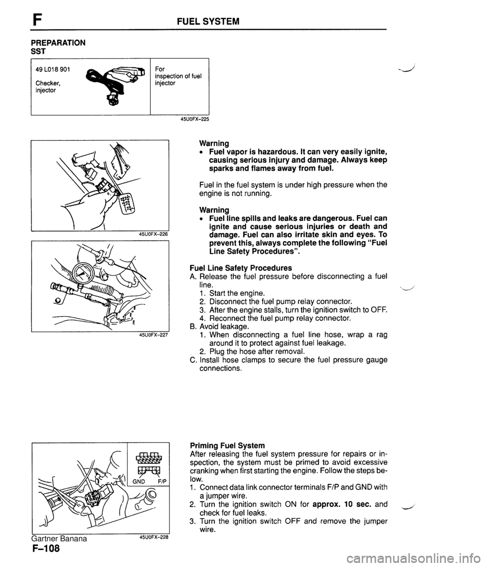
FUEL SYSTEM PREPARATION SST 49 LO1 8 901 For inspection of fuel Checker, injector injector Warning Fuel vapor is hazardous. It can very easily ignite, causing serious injury and damage. Always keep sparks and flames away from fuel. Fuel in the fuel system is under high pressure when the engine is not running. Warning Fuel line spills and leaks are dangerous. Fuel can ignite and cause serious injuries or death and damage. Fuel can also irritate skin and eyes. To prevent this, always complete the following "Fuel Line Safety Procedures". Fuel Line Safety Procedures A. Release the fuel pressure before disconnecting a fuel line. xd 1 . Start the engine. 2. Disconnect the fuel pump relay connector. 3. After the engine stalls, turn the ignition switch to OFF. 4. Reconnect the fuel pump relay connector. B. Avoid leakage. 1. When disconnecting a fuel line hose, wrap a rag around it to protect against fuel leakage. 2. Plug the hose after removal. C. Install hose clamps to secure the fuel pressure gauge connections. Priming Fuel System After releasing the fuel system pressure for repairs or in- spection, the system must be primed to avoid excessive cranking when first starting the engine. Follow the steps be- low. 1. Connect data link connector terminals F/P and GND with a jumper wire. 2. Turn the ignition switch ON for approx. 10 sec. and - check for fuel leaks. 3. Turn the ignition switch OFF and remove the jumper wire. Gartner Banana
Page 267 of 1708
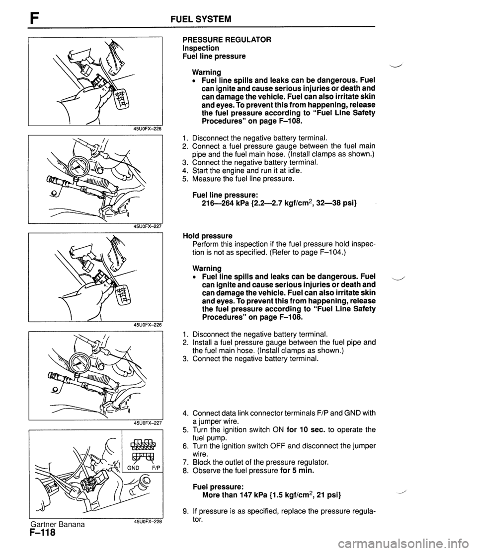
F FUEL SYSTEM PRESSURE REGULATOR Inspection Fuel line pressure d Warning Fuel line spills and leaks can be dangerous. Fuel can ignite and cause serious injuries or death and can damage the vehicle. Fuel can also irritate skin and eyes. To prevent this from happening, release the fuel pressure according to "Fuel Line Safety Procedures" on page F-108. 1. Disconnect the negative battery terminal. 2. Connect a fuel pressure gauge between the fuel main pipe and the fuel main hose. (Install clamps as shown.) 3. Connect the negative battery terminal. 4. Start the engine and run it at idle. 5. Measure the fuel line pressure. Fuel line pressure: 21 6-264 kPa (2.2-2.7 kgf/cm2, 32-38 psi) Hold pressure Perform this inspection if the fuel pressure hold inspec- tion is not as specified. (Refer to page F-104.) Warning Fuel line spills and leaks can be dangerous. Fuel ,-, can ignite and cause serious injuries or death and can damage the vehicle. Fuel can also irritate skin and eyes. To prevent this from happening, release the fuel pressure according to "Fuel Line Safety Procedures" on page F-108. 1. Disconnect the negative battery terminal. 2. Install a fuel pressure gauge between the fuel pipe and the fuel main hose. (Install clamps as shown.) 3. Connect the negative battery terminal. 4. Connect data link connector terminals F/P and GND with a jumper wire. 5. Turn the ignition switch ON for 10 sec. to operate the fuel pump. 6. Turn the ignition switch OFF and disconnect the jumper wire. 7. Block the outlet of the pressure regulator. 8. Observe the fuel pressure for 5 min. Fuel pressure: More than 147 kPa {I .5 kgf/cm2, 21 psi) 9. If pressure is as specified, replace the pressure regula- tor. Gartner Banana
Page 268 of 1708
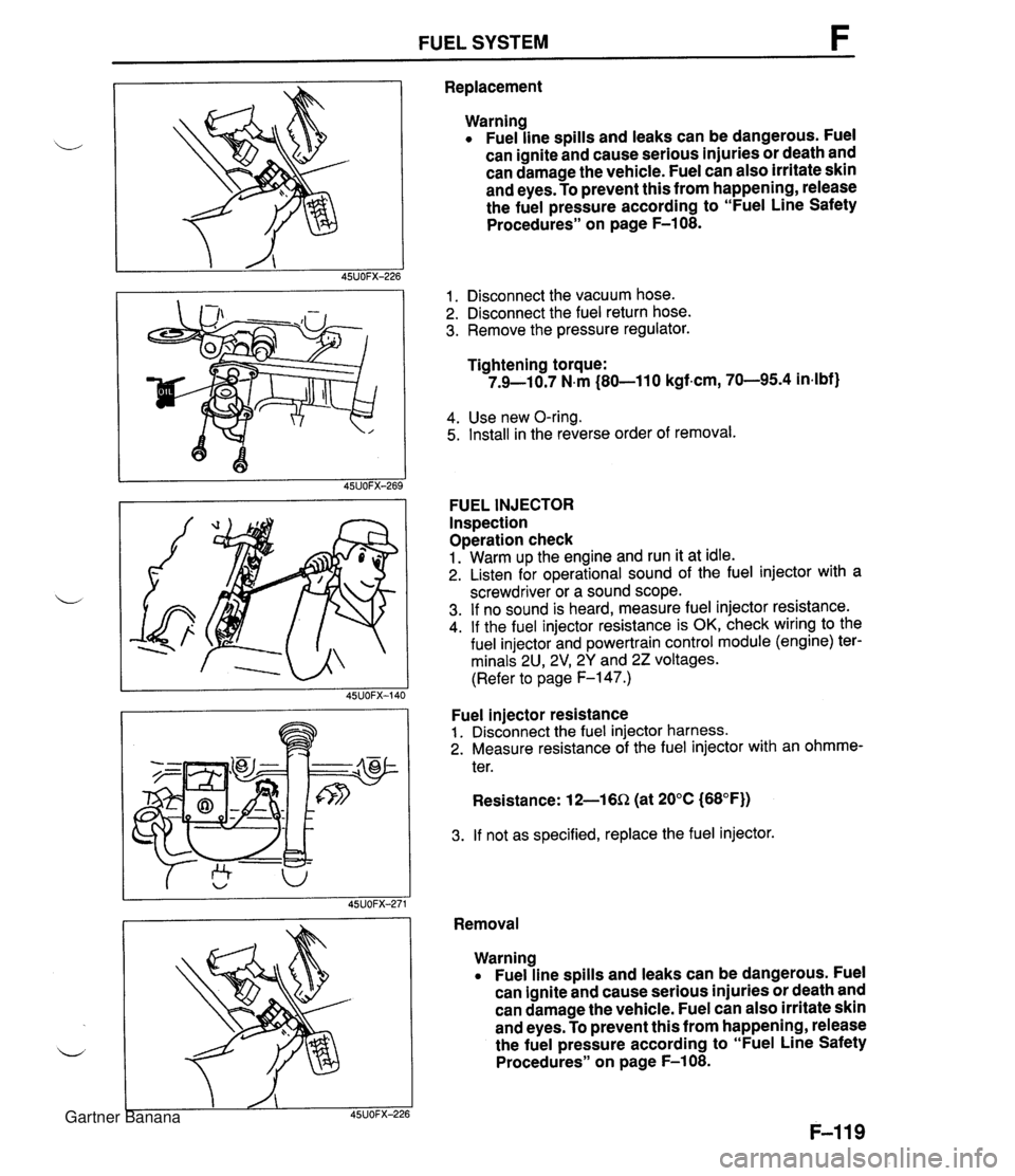
FUEL SYSTEM F Replacement Warning Fuel line spills and leaks can be dangerous. Fuel can ignite and cause serious injuries or death and can damage the vehicle. Fuel can also irritate skin and eyes. To prevent this from happening, release the fuel pressure according to "Fuel Line Safety Procedures" on page F-108. 1. Disconnect the vacuum hose. 2. Disconnect the fuel return hose. 3. Remove the pressure regulator. Tightening torque: 7.9-10.7 N.m (80-11 0 kgf-cm, 70-95.4 in4bf) 4. Use new O-ring. 5. Install in the reverse order of removal. FUEL INJECTOR Inspection Operation check 1. Warm up the engine and run it at idle. 2. Listen for operational sound of the fuel injector with a screwdriver or a sound scope. 3. If no sound is heard, measure fuel injector resistance. 4. If the fuel injector resistance is OK, check wiring to the fuel injector and powertrain control module (engine) ter- minals 2U, 2V1 2Y and 22 voltages. (Refer to page F-147.) Fuel injector resistance 1. Disconnect the fuel injector harness. 2. Measure resistance of the fuel injector with an ohmme- ter. Resistance: 12-16Q (at 20°C (68°F)) 3. If not as specified, replace the fuel injector. Removal Warning Fuel line spills and leaks can be dangerous. Fuel can ignite and cause serious injuries or death and can damage the vehicle. Fuel can also irritate skin and eyes. To prevent this from happening, release the fuel pressure according to "Fuel Line Safety Procedures" on page F-108. Gartner Banana
Page 270 of 1708
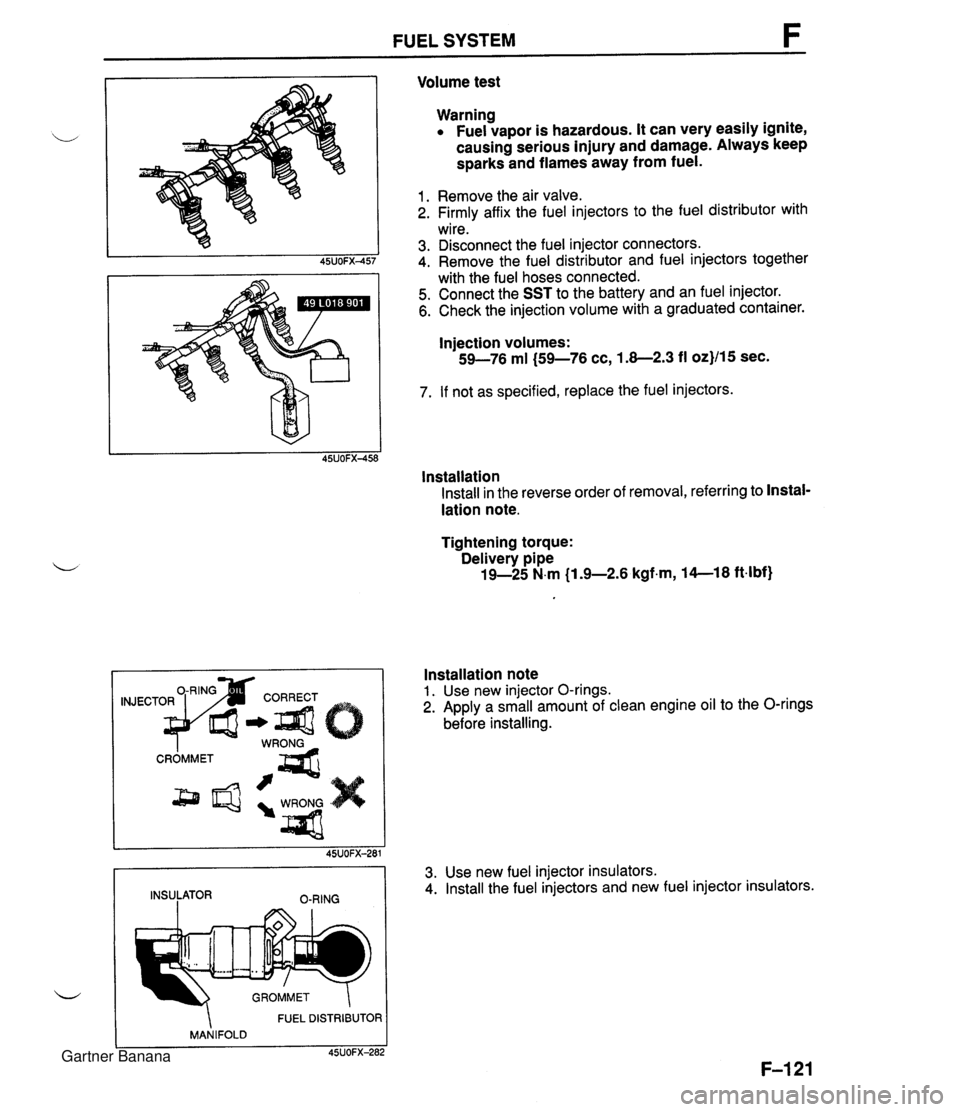
FUEL SYSTEM Volume test Warning Fuel vapor is hazardous. It can very easily ignite, causing serious injury and damage. Always keep sparks and flames away from fuel. 1. Remove the air valve. 2. Firmly affix the fuel injectors to the fuel distributor with wire. 3. Disconnect the fuel injector connectors. 4. Remove the fuel distributor and fuel injectors together with the fuel hoses connected. 5. Connect the SST to the battery and an fuel injector. 6. Check the injection volume with a graduated container. Injection volumes: 59-76 ml (59-76 cc, 1.8-2.3 fl oz}/15 sec. 7. If not as specified, replace the fuel injectors. lnstallation Install in the reverse order of removal, referring to Instal- lation note. Tightening torque: Delivery pipe 19-25 N.m (1 .%2.6 kgfm, 14--18 ft4bf) FUEL DISTRIBUTOR MANIFOLD C 45UOFX-282 Installation note 1. Use new injector O-rings. 2. Apply a small amount of clean engine oil to the O-rings before installing. 45UOFX-281 INSULATOR O-RING 3. Use new fuel injector insulators. 4. Install the fuel injectors and new fuel injector insulators. Gartner Banana
Page 271 of 1708
PRESSURE REGULATOR CONTROL SYSTEM PRESSURE REGULATOR CONTROL SYSTEM DATA LINK CONNECTOR - CLUTCH SWITCH (MT) (TEN TERMINAL) PARKINEUTRAL SWITCH (PCMT) (AT) THROTTLE POSITION SENSOR L 1 ,,,, INTAKE AIR TEMPERATURE 1 SENSOR (IN MASS AIRFLOW SENSOR) -;- ENGINE COOLANT TEMPERATURE SENSOR PRC SOLENOID VALVE CRANKSHAFT POSITION SENSOR PRESSURE REGULATOR PCME I Above 90°C {194OF} ( Above 70°C {158'F} I Throttle valve closed throttle position or no load condition I Approx. 150 1 I Operating condition Coolant temperature I Intake air temperature I Engine condition I I To prevent percolation of the fuel during hot restart idle, vacuum to the pressure regulator is momentarily cut, and the fuel injection pressure is increased to slightly more than 284 kPa (2.9 kgf/cm2, 41.2 psi}. Operating time (sec) Gartner Banana
Page 272 of 1708
PRESSURE REGULATOR CONTROL SYSTEM F PRESSURE REGULATOR / f PRC SOLENOID VALVE AIR FILTER U PRC SOLENOID VALVE lnspection (On-vehicle) 1. Start the engine and run it at idle. 2. Disconnect the vacuum hose from the pressure regula- tor. Verify that vacuum is felt. 3. Ground the PRC solenoid valve terminal B with a jumper wire. Verify that no vacuum is felt. 4. If vacuum exists, check the PRC solenoid valve. Inspection 1. Disconnect the vacuum hose from the PRC solenoid valve and vacuum pipe. 2. Blow through the PRC solenoid valve from port A. 3. Verify that air flows from port B. 4. Disconnect the PRC solenoid valve connector. 5. Connect battery positive voltage and a ground to the ter- minals of the PRC solenoid valve. 6. Blow through the PRC solenoid valve from the port A. 7. Verify that air flows from the valve air filter. 8. If not as specified, replace the PRC solenoid valve. Gartner Banana
Page 273 of 1708
F EXHAUST GAS RECIRCULATION (EGR) EXHAUST GAS RECIRCULATION (EGR) PREPARATION SST I 49 9200 162 Engine Signal Monitor 49 GO1 8 904 Sheet DESCRIPTION For inspection of EGR For inspection of EGR 49 GO1 8 903 For inspection of Adapter EGR harness / TO AIR CLEANER HOUSING I THROTTLE POSITION ENGINE COOLANT SENSOR SENSOR TEMPERATURE CRANKSHAFT SENSOR POSITION SENSOR EGR SOLENOID VALVE (VACUUM) EGR SOLENOID VALVE (VENT) / PCME I This ~~st~rn~recirculates a small amount of exhaust gas into the intake manifold to reduce the combus- tion temperature, and reduce the NOx emissions. This system consists of the EGR control valve, EGR function sensor, two solenoid valves, powertrain control module (engine) (PCME) and input devices. Gartner Banana