1994 JEEP CHEROKEE transmission
[x] Cancel search: transmissionPage 1267 of 1784
AW-4 AUTOMATIC TRANSMISSION
CONTENTS
page page
AW-4 IN-VEHICLE SERVICE............. 173
AW-4 TRANSMISSION DIAGNOSIS........ 167
AW-4 TRANSMISSION OVERHAUL........ 192
AW-4 TRANSMISSION REMOVAL AND
INSTALLATION....................... 189GENERAL INFORMATION................ 156
TRANSMISSION/TRANSFER CASE
SPECIFICATIONS..................... 320
GENERAL INFORMATION
INDEX
page page
Components and Operation................ 157
Description............................ 156
FirstÐThirdÐReverse Gear Components...... 159
Fourth Gear Overdrive Components......... 158
Geartrain Operation and Application Charts.... 159Hydraulic System........................ 160
Torque Converter........................ 158
Transmission Identification................. 157
Transmission Ranges and Shift Lever Positions . 157
DESCRIPTION
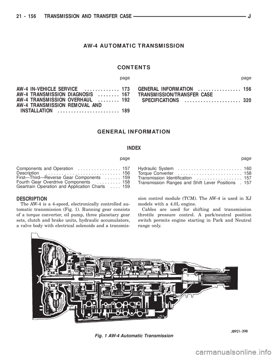
The AW-4 is a 4-speed, electronically controlled au-
tomatic transmission (Fig. 1). Running gear consists
of a torque converter, oil pump, three planetary gear
sets, clutch and brake units, hydraulic accumulators,
a valve body with electrical solenoids and a transmis-sion control module (TCM). The AW-4 is used in XJ
models with a 4.0L engine.
Cables are used for shifting and transmission
throttle pressure control. A park/neutral position
switch permits engine starting in Park and Neutral
range only.
Fig. 1 AW-4 Automatic Transmission
21 - 156 TRANSMISSION AND TRANSFER CASEJ
Page 1268 of 1784
The valve body solenoids are controlled by signals
from the transmission control module (TCM). Signal
sequence is determined by vehicle speed and throttle
position.
Fourth gear is an 0.75:1 ratio overdrive range.
First, second, third and reverse gear are conventional
ranges. Third gear ratio is 1:1. A separate planetary
gear set provides overdrive operation in fourth gear.
TRANSMISSION RANGES AND SHIFT LEVER
POSITIONS
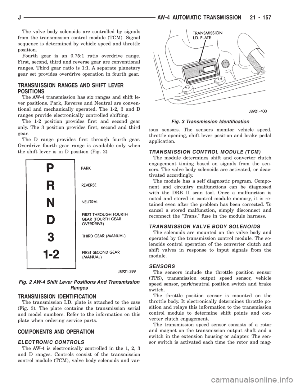
The AW-4 transmission has six ranges and shift le-
ver positions. Park, Reverse and Neutral are conven-
tional and mechanically operated. The 1-2, 3 and D
ranges provide electronically controlled shifting.
The 1-2 position provides first and second gear
only. The 3 position provides first, second and third
gear.
The D range provides first through fourth gear.
Overdrive fourth gear range is available only when
the shift lever is in D position (Fig. 2).
TRANSMISSION IDENTIFICATION
The transmission I.D. plate is attached to the case
(Fig. 3). The plate contains the transmission serial
and model numbers. Refer to the information on this
plate when ordering service parts.
COMPONENTS AND OPERATION
ELECTRONIC CONTROLS
The AW-4 is electronically controlled in the 1, 2, 3
and D ranges. Controls consist of the transmission
control module (TCM), valve body solenoids and var-ious sensors. The sensors monitor vehicle speed,
throttle opening, shift lever position and brake pedal
application.
TRANSMISSION CONTROL MODULE (TCM)
The module determines shift and converter clutch
engagement timing based on signals from the sen-
sors. The valve body solenoids are activated, or deac-
tivated accordingly.
The module has a self diagnostic program. Compo-
nent and circuitry malfunctions can be diagnosed
with the DRB II scan tool. Once a malfunction is
noted and stored in control module memory, it is re-
tained even after the problem has been corrected. To
cancel a stored malfunction, simply disconnect and
reconnect the9Trans.9fuse in the module harness.
TRANSMISSION VALVE BODY SOLENOIDS
The solenoids are mounted on the valve body and
operated by the transmission control module. The so-
lenoids control operation of the converter clutch and
shift valves in response to input signals from the
module.
SENSORS
The sensors include the throttle position sensor
(TPS), transmission output speed sensor, vehicle
speed sensor, park/neutral position switch and brake
switch.
The throttle position sensor is mounted on the
throttle body. It electronically determines throttle po-
sition and relays this information to the transmission
control module to determine shift points and con-
verter clutch engagement.
The transmission speed sensor consists of a rotor
and magnet on the transmission output shaft and a
switch in the extension housing or adapter. The sen-
sor switch is activated each time the rotor and mag-
Fig. 2 AW-4 Shift Lever Positions And Transmission
Ranges
Fig. 3 Transmission Identification
JAW-4 AUTOMATIC TRANSMISSION 21 - 157
Page 1269 of 1784
net complete one revolution. Sensor signals are sent
to the transmission control module.
The park/neutral position switch is mounted on the
valve body manual shaft. The switch signals shift
linkage and manual valve position to the transmis-
sion control module through an interconnecting har-
ness. The switch prevents engine starting in all gears
other than Park or Neutral.
The brake switch is in circuit with the torque con-
verter clutch solenoid. The switch disengages the
converter clutch whenever the brakes are applied.
The switch is mounted on the brake pedal bracket
and signals the transmission control module when
the pedal is pressed or released.
TORQUE CONVERTER
A four element torque converter is used for all ap-
plications. The converter consists of the front cover
and pump, stator, turbine, and an electronic modu-
lated converter clutch mechanism.
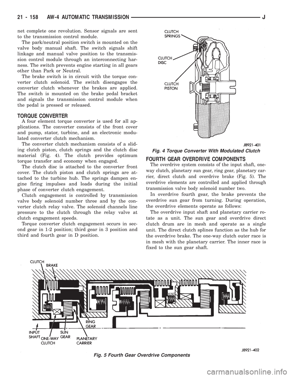
The converter clutch mechanism consists of a slid-
ing clutch piston, clutch springs and the clutch disc
material (Fig. 4). The clutch provides optimum
torque transfer and economy when engaged.
The clutch disc is attached to the converter front
cover. The clutch piston and clutch springs are at-
tached to the turbine hub. The springs dampen en-
gine firing impulses and loads during the initial
phase of converter clutch engagement.
Clutch engagement is controlled by transmission
valve body solenoid number three and by the con-
verter clutch relay valve. The solenoid channels line
pressure to the clutch through the relay valve at
clutch engagement speeds.
Torque converter clutch engagement occurs in sec-
ond gear in 1-2 position; third gear in 3 position and
third and fourth gear in D position.
FOURTH GEAR OVERDRIVE COMPONENTS
The overdrive system consists of the input shaft, one-
way clutch, planetary sun gear, ring gear, planetary car-
rier, direct clutch and overdrive brake (Fig. 5). The
overdrive elements are controlled and applied through
transmission valve body solenoid number two.
In overdrive fourth gear, the brake prevents the
overdrive sun gear from turning. During operation,
the overdrive elements operate as follows:
The overdrive input shaft and planetary carrier ro-
tate as a unit. The sun gear and overdrive direct
clutch drum are in mesh and operate as a single
unit. The direct clutch splines function as the hub for
the overdrive brake. The one-way clutch outer race is
in mesh with the planetary carrier. The inner race is
fixed to the sun gear shaft.
Fig. 5 Fourth Gear Overdrive Components
Fig. 4 Torque Converter With Modulated Clutch
21 - 158 AW-4 AUTOMATIC TRANSMISSIONJ
Page 1270 of 1784
FIRSTÐTHIRDÐREVERSE GEAR COMPONENTS
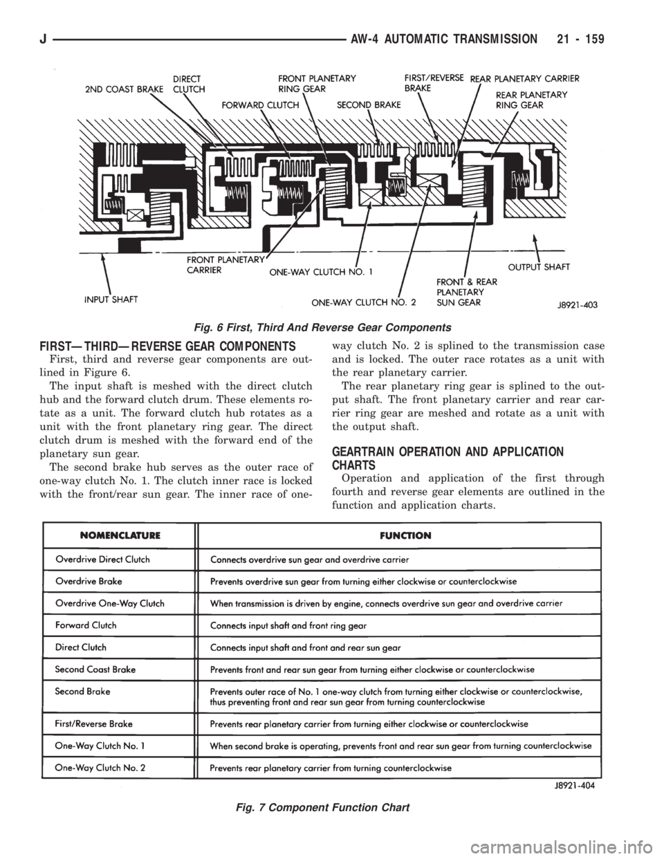
First, third and reverse gear components are out-
lined in Figure 6.
The input shaft is meshed with the direct clutch
hub and the forward clutch drum. These elements ro-
tate as a unit. The forward clutch hub rotates as a
unit with the front planetary ring gear. The direct
clutch drum is meshed with the forward end of the
planetary sun gear.
The second brake hub serves as the outer race of
one-way clutch No. 1. The clutch inner race is locked
with the front/rear sun gear. The inner race of one-way clutch No. 2 is splined to the transmission case
and is locked. The outer race rotates as a unit with
the rear planetary carrier.
The rear planetary ring gear is splined to the out-
put shaft. The front planetary carrier and rear car-
rier ring gear are meshed and rotate as a unit with
the output shaft.
GEARTRAIN OPERATION AND APPLICATION
CHARTS
Operation and application of the first through
fourth and reverse gear elements are outlined in the
function and application charts.
Fig. 6 First, Third And Reverse Gear Components
Fig. 7 Component Function Chart
JAW-4 AUTOMATIC TRANSMISSION 21 - 159
Page 1271 of 1784
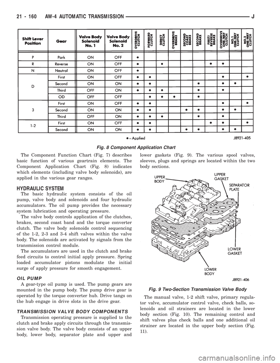
The Component Function Chart (Fig. 7) describes
basic function of various geartrain elements. The
Component Application Chart (Fig. 8) indicates
which elements (including valve body solenoids), are
applied in the various gear ranges.
HYDRAULIC SYSTEM
The basic hydraulic system consists of the oil
pump, valve body and solenoids and four hydraulic
accumulators. The oil pump provides the necessary
system lubrication and operating pressure.
The valve body controls application of the clutches,
brakes, second coast band and the torque converter
clutch. The valve body solenoids control sequencing
of the 1-2, 2-3 and 3-4 shift valves within the valve
body. The solenoids are activated by signals from the
transmission control module.
The accumulators are used in the clutch and brake
feed circuits to control initial apply pressure. Spring
loaded accumulator pistons modulate the initial
surge of apply pressure for smooth engagement.
OIL PUMP
A gear-type oil pump is used. The pump gears are
mounted in the pump body. The pump drive gear is
operated by the torque converter hub. Drive tangs on
the hub engage in drive slots in the drive gear.
TRANSMISSION VALVE BODY COMPONENTS
Transmission operating pressure is supplied to the
clutch and brake apply circuits through the transmis-
sion valve body. The valve body consists of an upper
body, lower body, separator plate and upper andlower gaskets (Fig. 9). The various spool valves,
sleeves, plugs and springs are located within the two
body sections.
The manual valve, 1-2 shift valve, primary regula-
tor valve, accumulator control valve, check balls, so-
lenoids and oil strainers are located in the lower
body section (Fig. 10). The remaining control and
shift valves plus check balls and one additional oil
strainer are located in the upper body section (Fig.
11).
Fig. 8 Component Application Chart
Fig. 9 Two-Section Transmission Valve Body
21 - 160 AW-4 AUTOMATIC TRANSMISSIONJ
Page 1272 of 1784
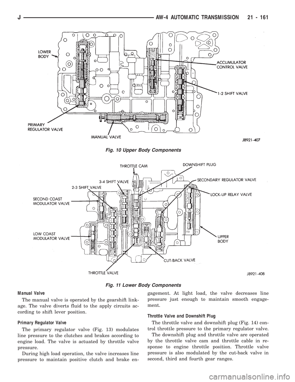
Manual Valve
The manual valve is operated by the gearshift link-
age. The valve diverts fluid to the apply circuits ac-
cording to shift lever position.
Primary Regulator Valve
The primary regulator valve (Fig. 13) modulates
line pressure to the clutches and brakes according to
engine load. The valve is actuated by throttle valve
pressure.
During high load operation, the valve increases line
pressure to maintain positive clutch and brake en-gagement. At light load, the valve decreases line
pressure just enough to maintain smooth engage-
ment.
Throttle Valve and Downshift Plug
The throttle valve and downshift plug (Fig. 14) con-
trol throttle pressure to the primary regulator valve.
The downshift plug and throttle valve are operated
by the throttle valve cam and throttle cable in re-
sponse to engine throttle position. Throttle valve
pressure is also modulated by the cut-back valve in
second, third and fourth gear ranges.
Fig. 11 Lower Body Components
Fig. 10 Upper Body Components
JAW-4 AUTOMATIC TRANSMISSION 21 - 161
Page 1273 of 1784
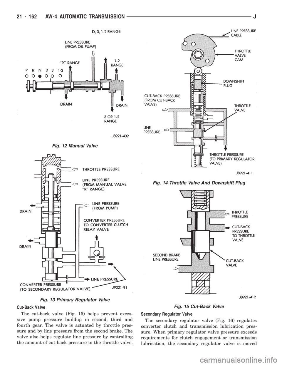
Cut-Back Valve
The cut-back valve (Fig. 15) helps prevent exces-
sive pump pressure buildup in second, third and
fourth gear. The valve is actuated by throttle pres-
sure and by line pressure from the second brake. The
valve also helps regulate line pressure by controlling
the amount of cut-back pressure to the throttle valve.Secondary Regulator Valve
The secondary regulator valve (Fig. 16) regulates
converter clutch and transmission lubrication pres-
sure. When primary regulator valve pressure exceeds
requirements for clutch engagement or transmission
lubrication, the secondary regulator valve is moved
Fig. 12 Manual Valve
Fig. 13 Primary Regulator Valve
Fig. 14 Throttle Valve And Downshift Plug
Fig. 15 Cut-Back Valve
21 - 162 AW-4 AUTOMATIC TRANSMISSIONJ
Page 1274 of 1784
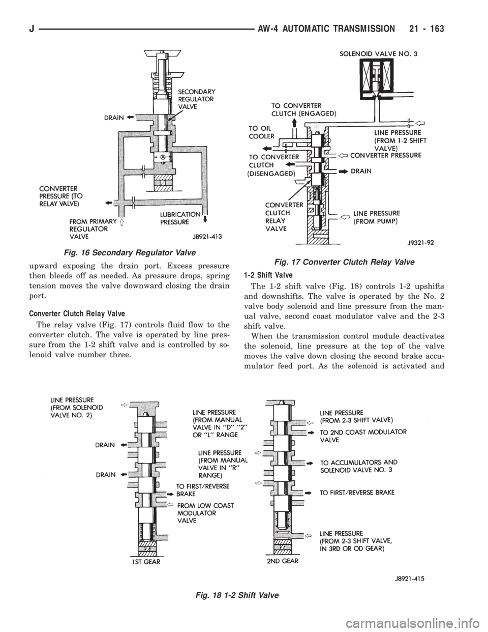
upward exposing the drain port. Excess pressure
then bleeds off as needed. As pressure drops, spring
tension moves the valve downward closing the drain
port.
Converter Clutch Relay Valve
The relay valve (Fig. 17) controls fluid flow to the
converter clutch. The valve is operated by line pres-
sure from the 1-2 shift valve and is controlled by so-
lenoid valve number three.1-2 Shift Valve
The 1-2 shift valve (Fig. 18) controls 1-2 upshifts
and downshifts. The valve is operated by the No. 2
valve body solenoid and line pressure from the man-
ual valve, second coast modulator valve and the 2-3
shift valve.
When the transmission control module deactivates
the solenoid, line pressure at the top of the valve
moves the valve down closing the second brake accu-
mulator feed port. As the solenoid is activated and
Fig. 16 Secondary Regulator Valve
Fig. 18 1-2 Shift Valve
Fig. 17 Converter Clutch Relay Valve
JAW-4 AUTOMATIC TRANSMISSION 21 - 163