1994 JEEP CHEROKEE side marker
[x] Cancel search: side markerPage 1459 of 1784
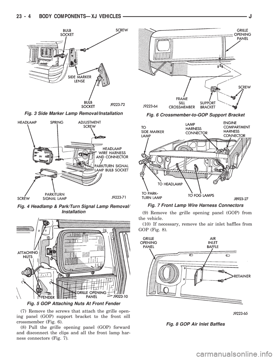
(7) Remove the screws that attach the grille open-
ing panel (GOP) support bracket to the front sill
crossmember (Fig. 6).
(8) Pull the grille opening panel (GOP) forward
and disconnect the clips and all the front lamp har-
ness connectors (Fig. 7).(9) Remove the grille opening panel (GOP) from
the vehicle.
(10) If necessary, remove the air inlet baffles from
GOP (Fig. 8).
Fig. 3 Side Marker Lamp Removal/Installation
Fig. 4 Headlamp & Park/Turn Signal Lamp Removal/
Installation
Fig. 5 GOP Attaching Nuts At Front Fender
Fig. 6 Crossmember-to-GOP Support Bracket
Fig. 7 Front Lamp Wire Harness Connectors
Fig. 8 GOP Air Inlet Baffles
23 - 4 BODY COMPONENTSÐXJ VEHICLESJ
Page 1460 of 1784
INSTALLATION
(1) Place the grille opening panel (GOP) on bumper
and connect all front lamp wire harness connectors.
(2) Position the grille opening panel (GOP) on the
vehicle and install the side and upper nuts. Tighten
nuts to 7 Nzm (58 in-lbs) torque.
(3) Install the screw to attach grille opening panel
(GOP) to the crossmember support bracket. Tighten
the screw to 1 Nzm (11 in-lbs) torque.
(4) Install headlamps and park/turn signal lamps
in GOP.(5) Install the headlamp bezels on the GOP.
Tighten the screws to 1 Nzm (13 in-lbs) torque.
(6) Install the side marker lenses and screws on
the grille opening panel (GOP). Tighten the screws to
1Nzm (13 in-lbs) torque.
(7) Install the grille on the GOP. Tighten screws to
1Nzm (13 in-lbs) torque.
(8) Adjust the headlamp aim, if necessary. Refer to
the headlamp beam adjustment procedure within
Group 8L.
RADIATOR SUPPORT CROSSMEMBER
REMOVAL
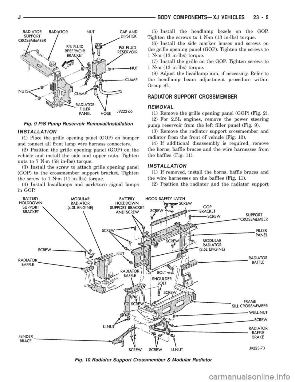
(1) Remove the grille opening panel (GOP) (Fig. 2).
(2) For 2.5L engines, remove the power steering
pump reservoir from the left filler panel (Fig. 9).
(3) Remove the radiator support crossmember and
radiator from the front of vehicle (Fig. 10).
(4) If additional disassembly is required, remove
the horns, baffle braces and the wire harnesses from
the baffles (Fig. 11).
INSTALLATION
(1) If removed, install the horns, baffle braces and
the wire harnesses on the baffles (Fig. 11).
(2) Position the radiator and the radiator support
Fig. 9 P/S Pump Reservoir Removal/Installation
Fig. 10 Radiator Support Crossmember & Modular Radiator
JBODY COMPONENTSÐXJ VEHICLES 23 - 5
Page 1598 of 1784
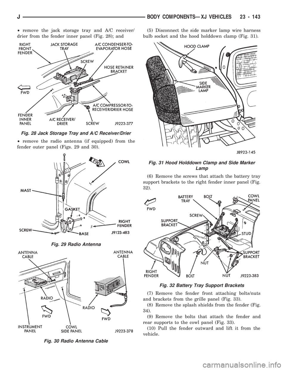
²remove the jack storage tray and A/C receiver/
drier from the fender inner panel (Fig. 28); and
²remove the radio antenna (if equipped) from the
fender outer panel (Figs. 29 and 30).(5) Disconnect the side marker lamp wire harness
bulb socket and the hood holddown clamp (Fig. 31).
(6) Remove the screws that attach the battery tray
support brackets to the right fender inner panel (Fig.
32).
(7) Remove the fender front attaching bolts/nuts
and brackets from the grille panel (Fig. 33).
(8) Remove the splash shields from the fender (Fig.
34).
(9) Remove the bolts that attach the fender and
rear supports to the cowl panel (Fig. 33).
(10) Pull the fender outward and lift it from the
vehicle.
Fig. 28 Jack Storage Tray and A/C Receiver/Drier
Fig. 29 Radio Antenna
Fig. 30 Radio Antenna Cable
Fig. 31 Hood Holddown Clamp and Side Marker
Lamp
Fig. 32 Battery Tray Support Brackets
JBODY COMPONENTSÐXJ VEHICLES 23 - 143
Page 1599 of 1784
INSTALLATION
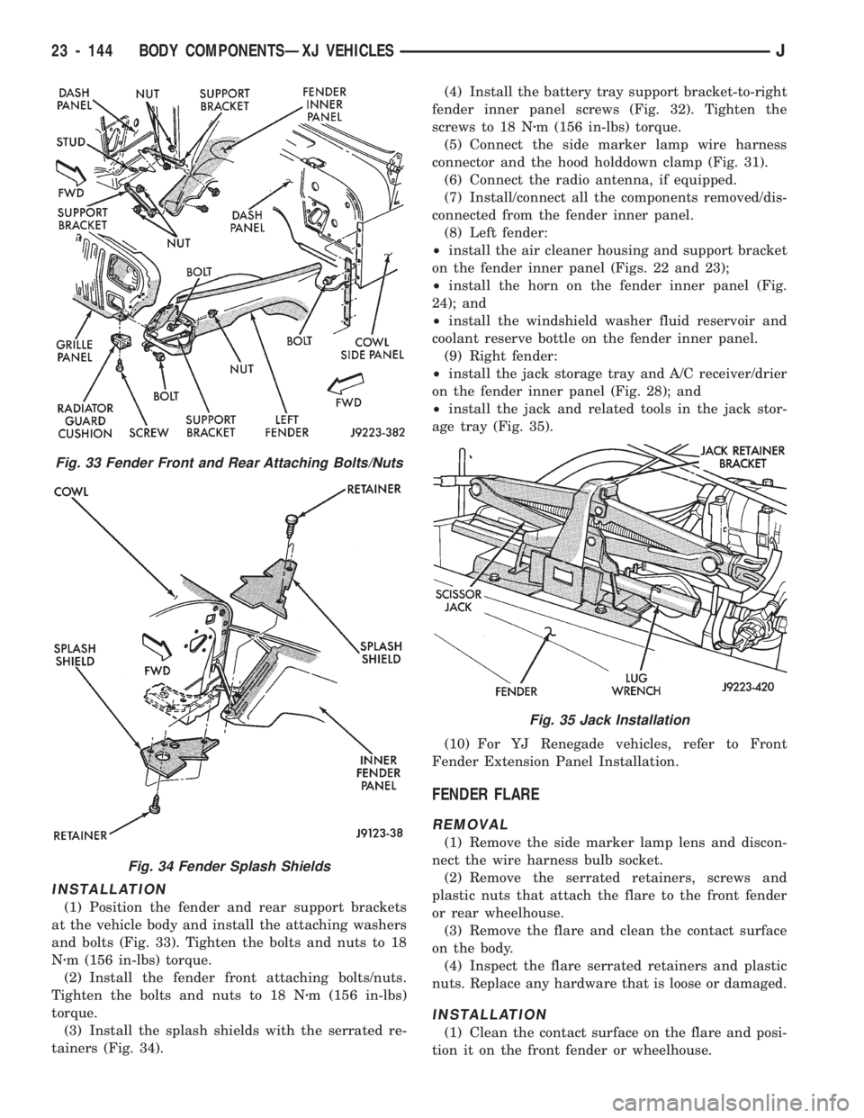
(1) Position the fender and rear support brackets
at the vehicle body and install the attaching washers
and bolts (Fig. 33). Tighten the bolts and nuts to 18
Nzm (156 in-lbs) torque.
(2) Install the fender front attaching bolts/nuts.
Tighten the bolts and nuts to 18 Nzm (156 in-lbs)
torque.
(3) Install the splash shields with the serrated re-
tainers (Fig. 34).(4) Install the battery tray support bracket-to-right
fender inner panel screws (Fig. 32). Tighten the
screws to 18 Nzm (156 in-lbs) torque.
(5) Connect the side marker lamp wire harness
connector and the hood holddown clamp (Fig. 31).
(6) Connect the radio antenna, if equipped.
(7) Install/connect all the components removed/dis-
connected from the fender inner panel.
(8) Left fender:
²install the air cleaner housing and support bracket
on the fender inner panel (Figs. 22 and 23);
²install the horn on the fender inner panel (Fig.
24); and
²install the windshield washer fluid reservoir and
coolant reserve bottle on the fender inner panel.
(9) Right fender:
²install the jack storage tray and A/C receiver/drier
on the fender inner panel (Fig. 28); and
²install the jack and related tools in the jack stor-
age tray (Fig. 35).
(10) For YJ Renegade vehicles, refer to Front
Fender Extension Panel Installation.
FENDER FLARE
REMOVAL
(1) Remove the side marker lamp lens and discon-
nect the wire harness bulb socket.
(2) Remove the serrated retainers, screws and
plastic nuts that attach the flare to the front fender
or rear wheelhouse.
(3) Remove the flare and clean the contact surface
on the body.
(4) Inspect the flare serrated retainers and plastic
nuts. Replace any hardware that is loose or damaged.
INSTALLATION
(1) Clean the contact surface on the flare and posi-
tion it on the front fender or wheelhouse.
Fig. 33 Fender Front and Rear Attaching Bolts/Nuts
Fig. 34 Fender Splash Shields
Fig. 35 Jack Installation
23 - 144 BODY COMPONENTSÐXJ VEHICLESJ
Page 1604 of 1784
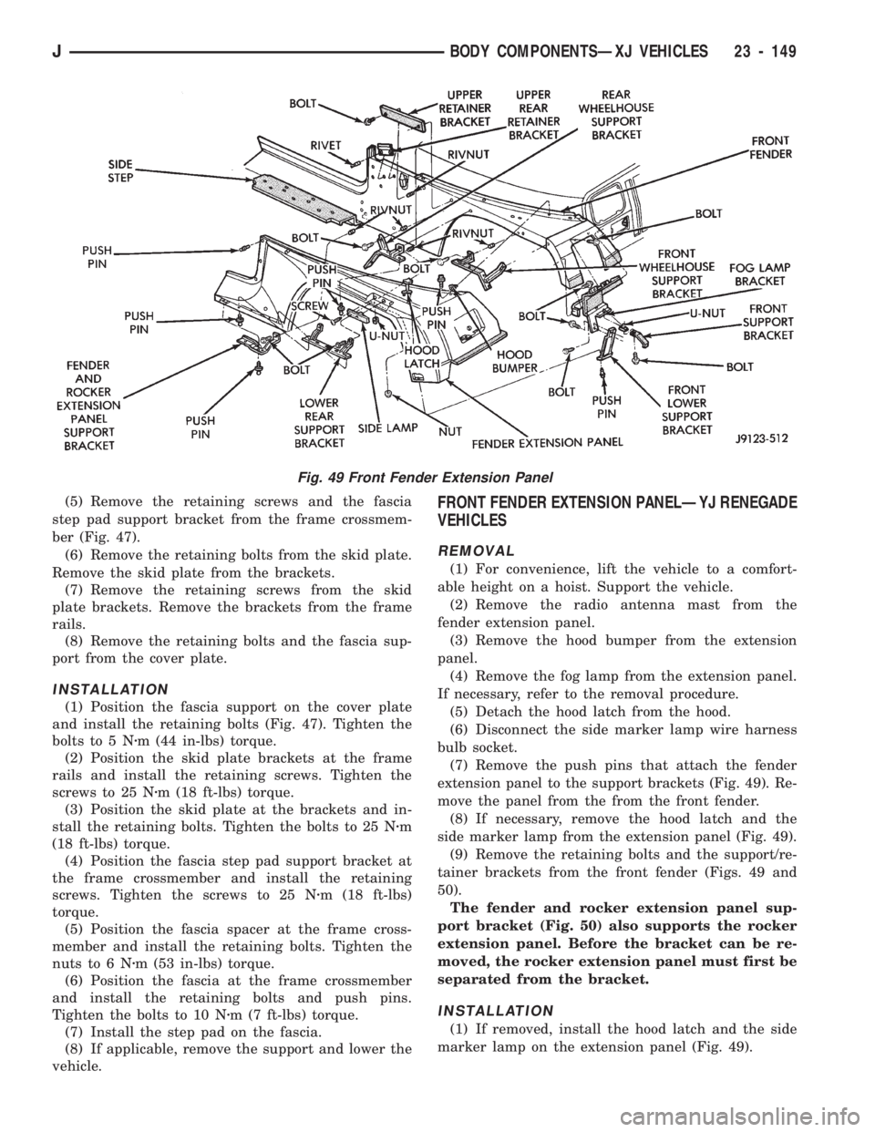
(5) Remove the retaining screws and the fascia
step pad support bracket from the frame crossmem-
ber (Fig. 47).
(6) Remove the retaining bolts from the skid plate.
Remove the skid plate from the brackets.
(7) Remove the retaining screws from the skid
plate brackets. Remove the brackets from the frame
rails.
(8) Remove the retaining bolts and the fascia sup-
port from the cover plate.
INSTALLATION
(1) Position the fascia support on the cover plate
and install the retaining bolts (Fig. 47). Tighten the
bolts to 5 Nzm (44 in-lbs) torque.
(2) Position the skid plate brackets at the frame
rails and install the retaining screws. Tighten the
screws to 25 Nzm (18 ft-lbs) torque.
(3) Position the skid plate at the brackets and in-
stall the retaining bolts. Tighten the bolts to 25 Nzm
(18 ft-lbs) torque.
(4) Position the fascia step pad support bracket at
the frame crossmember and install the retaining
screws. Tighten the screws to 25 Nzm (18 ft-lbs)
torque.
(5) Position the fascia spacer at the frame cross-
member and install the retaining bolts. Tighten the
nuts to 6 Nzm (53 in-lbs) torque.
(6) Position the fascia at the frame crossmember
and install the retaining bolts and push pins.
Tighten the bolts to 10 Nzm (7 ft-lbs) torque.
(7) Install the step pad on the fascia.
(8) If applicable, remove the support and lower the
vehicle.
FRONT FENDER EXTENSION PANELÐYJ RENEGADE
VEHICLES
REMOVAL
(1) For convenience, lift the vehicle to a comfort-
able height on a hoist. Support the vehicle.
(2) Remove the radio antenna mast from the
fender extension panel.
(3) Remove the hood bumper from the extension
panel.
(4) Remove the fog lamp from the extension panel.
If necessary, refer to the removal procedure.
(5) Detach the hood latch from the hood.
(6) Disconnect the side marker lamp wire harness
bulb socket.
(7) Remove the push pins that attach the fender
extension panel to the support brackets (Fig. 49). Re-
move the panel from the from the front fender.
(8) If necessary, remove the hood latch and the
side marker lamp from the extension panel (Fig. 49).
(9) Remove the retaining bolts and the support/re-
tainer brackets from the front fender (Figs. 49 and
50).
The fender and rocker extension panel sup-
port bracket (Fig. 50) also supports the rocker
extension panel. Before the bracket can be re-
moved, the rocker extension panel must first be
separated from the bracket.
INSTALLATION
(1) If removed, install the hood latch and the side
marker lamp on the extension panel (Fig. 49).
Fig. 49 Front Fender Extension Panel
JBODY COMPONENTSÐXJ VEHICLES 23 - 149
Page 1605 of 1784
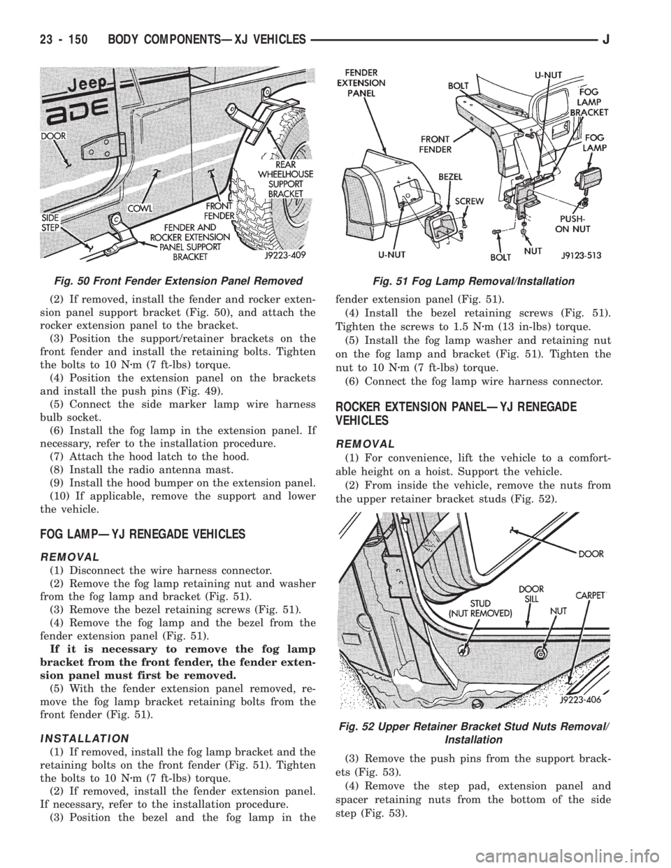
(2) If removed, install the fender and rocker exten-
sion panel support bracket (Fig. 50), and attach the
rocker extension panel to the bracket.
(3) Position the support/retainer brackets on the
front fender and install the retaining bolts. Tighten
the bolts to 10 Nzm (7 ft-lbs) torque.
(4) Position the extension panel on the brackets
and install the push pins (Fig. 49).
(5) Connect the side marker lamp wire harness
bulb socket.
(6) Install the fog lamp in the extension panel. If
necessary, refer to the installation procedure.
(7) Attach the hood latch to the hood.
(8) Install the radio antenna mast.
(9) Install the hood bumper on the extension panel.
(10) If applicable, remove the support and lower
the vehicle.
FOG LAMPÐYJ RENEGADE VEHICLES
REMOVAL
(1) Disconnect the wire harness connector.
(2) Remove the fog lamp retaining nut and washer
from the fog lamp and bracket (Fig. 51).
(3) Remove the bezel retaining screws (Fig. 51).
(4) Remove the fog lamp and the bezel from the
fender extension panel (Fig. 51).
If it is necessary to remove the fog lamp
bracket from the front fender, the fender exten-
sion panel must first be removed.
(5) With the fender extension panel removed, re-
move the fog lamp bracket retaining bolts from the
front fender (Fig. 51).
INSTALLATION
(1) If removed, install the fog lamp bracket and the
retaining bolts on the front fender (Fig. 51). Tighten
the bolts to 10 Nzm (7 ft-lbs) torque.
(2) If removed, install the fender extension panel.
If necessary, refer to the installation procedure.
(3) Position the bezel and the fog lamp in thefender extension panel (Fig. 51).
(4) Install the bezel retaining screws (Fig. 51).
Tighten the screws to 1.5 Nzm (13 in-lbs) torque.
(5) Install the fog lamp washer and retaining nut
on the fog lamp and bracket (Fig. 51). Tighten the
nut to 10 Nzm (7 ft-lbs) torque.
(6) Connect the fog lamp wire harness connector.
ROCKER EXTENSION PANELÐYJ RENEGADE
VEHICLES
REMOVAL
(1) For convenience, lift the vehicle to a comfort-
able height on a hoist. Support the vehicle.
(2) From inside the vehicle, remove the nuts from
the upper retainer bracket studs (Fig. 52).
(3) Remove the push pins from the support brack-
ets (Fig. 53).
(4) Remove the step pad, extension panel and
spacer retaining nuts from the bottom of the side
step (Fig. 53).
Fig. 50 Front Fender Extension Panel RemovedFig. 51 Fog Lamp Removal/Installation
Fig. 52 Upper Retainer Bracket Stud Nuts Removal/
Installation
23 - 150 BODY COMPONENTSÐXJ VEHICLESJ
Page 1747 of 1784
BODY SOLENOIDS, TRANSMISSION
VALVE ............................21-175
BODY STRIPES/DECALS...........23-25,23-153
BODY, THROTTLE.................14-29,14-59
BODY UNDERCOAT....................23-203
BOOSTER CHECK VALVE TEST, POWER......5-11
BOOSTER INSTALLATION, POWER
BRAKE..........................5-23,5-51
BOOSTER OPERATION, POWER BRAKE......5-22
BOOSTER, POWER BRAKE............5-22,5-40
BOOSTER REMOVAL, POWER BRAKE . . . 5-22,5-51
BOOSTER TEST, MASTER CYLINDER/
POWER.............................5-11
BOOSTER VACUUM TEST, POWER..........5-12
BORES, HONING CYLINDER................9-2
BOX, GLOVE.........................23-194
BRACKET, FUEL FILTER.................23-86
BRACKET, FUEL FILTER SHIELD...........13-17
BRACKET, I/P TWEETER SPEAKER/
COURTESY LAMP SUPPORT............23-95
BRACKET, MUFFLER/TAILPIPE HANGER.....13-16
BRACKET, REARVIEW MIRROR
RETAINING........................23-183
BRACKET REPLACEMENT, INTERIOR
REARVIEW MIRROR SUPPORT..........23-75
BRACKETS, CATALYTIC CONVERTER/
MUFFLER/TAILPIPE SUPPORT...........23-85
BRACKETSÐXJ VEHICLES, SPARE TIRE/
WHEEL HOLDDOWN AND FLOOR.......23-128
BRAKE ADJUSTMENT, DRUM..............5-35
BRAKE ADJUSTMENT PARKING............5-63
BRAKE BLEEDINGÐBRAKE FLUID AND
LEVELÐBRAKELINES AND HOSES........5-13
BRAKE BLEEDINGÐWITH ABS BRAKES.....5-14
BRAKE BLEEDINGÐWITH STANDARD
BRAKES.............................5-13
BRAKE BOOSTER INSTALLATION,
POWER.........................5-23,5-51
BRAKE BOOSTER OPERATION, POWER......5-22
BRAKE BOOSTER, POWER............5-22,5-40
BRAKE BOOSTER REMOVAL, POWER . . . 5-22,5-51
BRAKE CABLE TENSIONER REPLACEMENT
(XJ), PARKING........................5-61
BRAKE CHECK, PRELIMINARY..............5-7
BRAKE COMPONENTS, WHEEL.............5-1
BRAKE DIAGNOSIS, ABS..................5-3
BRAKE DIAGNOSIS, SERVICE..............5-7
BRAKE DRUM REFINISHING..............5-37
BRAKE FLUID CONTAMINATION............5-13
BRAKE FLUID, IMPORTANCE OF CLEAN.....5-48
BRAKE FLUID LEVEL....................5-13
BRAKE FLUID, RECOMMENDED........5-13,5-48
BRAKE FLUID TUBE RETAINER CLIP,
FUEL AND; BODY COMPONENTSÐXJ
VEHICLES..........................23-86
BRAKE FLUID TUBE RETAINER CLIP,
FUEL AND; FRAME AND BUMPERS......13-16
BRAKE FLUID/LUBRICANTS/CLEANING
SOLVENTS............................5-1
BRAKE FRONT CABLE REPLACEMENT
(YJ), PARKING........................5-62
BRAKE INDICATOR INOPERATIVE..........8E-4
BRAKE INDICATOR LAMP; INSTRUMENT
PANEL AND GAUGESÐXJ...............8E-2
BRAKE INDICATOR LAMP; INSTRUMENT
PANEL AND GAUGESÐYJ
..............8E-16
BRAKE LEVER INSTALLATION (XJ WITH
FULLCONSOLE), PARKING
..............5-60
BRAKE LEVER INSTALLATION (XJ WITH
MINICONSOLE), PARKING
...............5-58
BRAKE LEVER INSTALLATION (XJ
WITHOUT CONSOLE), PARKING
..........5-60
BRAKE LEVER REMOVAL (XJ WITH FULL
CONSOLE), PARKING
..................5-59
BRAKE LEVER REMOVAL (XJ WITH MINI
CONSOLE), PARKING
..................5-58
BRAKE LEVER REMOVAL (XJ WITHOUT
CONSOLE), PARKING
..................5-60
BRAKE OPERATION, PARKING
.............5-56
BRAKE OVERHAUL, SECOND
............21-232
BRAKE PACK REQUIREMENTS, AW-4
CLUTCH
...........................21-328
BRAKE PEDAL AND BRAKELIGHT
SWITCH
.............................5-65
BRAKE PEDAL INSTALLATION
.............5-66BRAKE PEDAL INSTALLATION (YJ),
PARKING............................5-61
BRAKE PEDAL REMOVAL.................5-65
BRAKE PEDAL REMOVAL (YJ), PARKING....5-61
BRAKE PEDAL SERVICE..................5-65
BRAKE PISTON AND TRANSMISSION
CASE OVERHAUL, FIRST-REVERSE......21-237
BRAKE PROBLEMS, DIAGNOSING
PARKING............................5-10
BRAKE PROBLEMS, DIAGNOSING
SERVICE.............................5-8
BRAKE REAR CABLE REPLACEMENT
(XJ), PARKING........................5-62
BRAKE REAR CABLE REPLACEMENT (YJ),
PARKING............................5-63
BRAKE ROTOR REFINISHING, DISC.........5-32
BRAKE ROTOR RUNOUT, DISC............5-31
BRAKE ROTOR THICKNESS, DISC..........5-31
BRAKE ROTOR THICKNESS VARIATION,
DISC...............................5-31
BRAKE SAFETY PRECAUTIONS.............5-2
BRAKE SERVO, SECOND COAST.........21-181
BRAKE SWITCH.......................14-54
BRAKE SWITCHÐPCM INPUT............14-20
BRAKE SYSTEM (ABS), ANTILOCK..........5-1
BRAKE SYSTEM (ABS) INDICATOR
LAMP, ANTI-LOCK.....................8E-2
BRAKE SYSTEM OPERATION, ANTILOCK.....5-43
BRAKE SYSTEM, POWER.................0-32
BRAKE TORQUE SPECIFICATIONS..........5-67
BRAKE WARNING LIGHT DISPLAY...........5-4
BRAKE WARNING LIGHTS.................5-1
BRAKELIGHT SWITCH ADJUSTMENT........5-66
BRAKELIGHT SWITCH, BRAKE PEDAL.......5-65
BRAKELIGHT SWITCH INSTALLATION.......5-66
BRAKELIGHT SWITCH REMOVAL...........5-66
BRAKELINE CHARTS....................5-15
BRAKELINES AND HOSES................5-15
BRAKELINING MATERIAL..................5-1
BRAKES, BRAKE BLEEDINGÐWITH ABS.....5-14
BRAKES, BRAKE BLEEDINGÐWITH
STANDARD..........................5-13
BRAKES, DISC.........................5-24
BRAKES, DRUM........................5-34
BRAKES, PARKING......................5-56
BRAKES, POWER........................5-1
BRAKESHOE INSTALLATION, DISC..........5-26
BRAKESHOE INSTALLATION, DRUM........5-34
BRAKESHOE REMOVAL, DISC.............5-25
BRAKESHOE REMOVAL, DRUM............5-34
BRAKING MODE, ABS OPERATION IN
ANTILOCK...........................5-43
BRAKING MODE, ABS OPERATION
IN NORMAL..........................5-43
BREAK-IN, ENGINE......................0-13
BRUSH GUARD........................23-3
BUCKET SEAT COMPONENTS, POWER....23-106
BUCKET SEAT CUSHION AND COVER......23-98
BUCKET SEAT PLATFORM AND TRACKS . . . 23-105
BUCKET SEATBACK COVER AND FRAME . . . 23-100
BUCKET SEATBACK RECONDITIONING.....23-102
BUCKET SEATS, FRONT.................23-97
BUFFING AND POLISHING..............23-203
BULB REPLACEMENT, BACK-UP/REAR
TURN SIGNAL/TAIL LAMP...............8L-9
BULB REPLACEMENT, FRONT PARK/
TURN SIGNAL LAMP
...................8L-8
BULB REPLACEMENT, HEADLAMP
..........8L-3
BULB REPLACEMENT, INSTRUMENT
CLUSTER
...........................8E-19
BULB REPLACEMENT, SIDE MARKER
LAMP
...............................8L-7
BULB REPLACEMENT, UNDERHOOD
LAMP
..............................8L-18
BULB REPLACEMENTÐYJ VEHICLES,
HARDTOP DOME/CARGO LAMP
.........8L-20
BULB/ELEMENT REPLACEMENT, FOG
LAMP
..............................8L-13
BUMPER, FRONT
..................13-3,13-14
BUMPER, LIFTGATE LICENSE PLATE
SCREW ANCHOR
.....................23-72
BUMPER, REAR
...................13-6,13-18
BUMPER, REAR JOUNCE
................13-18
BUMPERÐXJ VEHICLES, REAR
SEATBACK LATCH STRIKER
...........23-111BUMPERS AND FRAME ATTACHED
COMPONENTS, YJ....................13-14
BUMPERS, FUEL FILLER DOOR...........23-31
BUMPERS, XJ.........................13-3
BUSHING AND PISTON CLEARANCE, AW-
4 ................................21-326
BUSHING REPLACEMENT, AXLE.......2-11,2-32
BUSHING REPLACEMENT, LEAF SPRING
EYE; FRONT SUSPENSION AND AXLE.....2-15
BUSHING REPLACEMENT, LEAF SPRING
EYE; REAR SUSPENSION AND AXLES . . . 3-4,3-6
BUZZER SYSTEM, CHIME/WARNING........8A-1
CABLE, ACCELERATOR PEDAL AND
THROTTLE.....................14-16,14-54
CABLE ADJUSTMENT, PARK INTERLOCK . . . 21-186
CABLE ADJUSTMENT, SHIFT............21-186
CABLE ADJUSTMENT, TRANSMISSION
THROTTLE....................21-98,21-185
CABLE ADJUSTMENT, TRANSMISSION
THROTTLE VALVE....................21-70
CABLE ADJUSTMENT (XJ), PARK
INTERLOCK.........................21-97
CABLE ADJUSTMENT (XJ), SHIFT.........21-97
CABLE REPLACEMENT, HEATER
CONTROL..........................24-30
CABLE REPLACEMENT, LATCH
RELEASE...........................23-10
CABLE REPLACEMENT, SERVO............8H-9
CABLE REPLACEMENT, TRANSMISSION
THROTTLE.........................21-184
CABLE REPLACEMENT (XJ),
PARKING BRAKE REAR.................5-62
CABLE REPLACEMENT (YJ), PARKING
BRAKE FRONT........................5-62
CABLE REPLACEMENT (YJ), PARKING
BRAKE REAR.........................5-63
CABLE RESISTANCE, SPARK PLUG........8D-18
CABLE TENSIONER REPLACEMENT (XJ),
PARKING BRAKE......................5-61
CABLE, THROTTLE.....................14-16
CABLEÐCONSOLE SHIFT AUTOMATIC,
PARK-LOCK.........................19-45
CABLES, DISTRIBUTOR CAP AND ROTOR,
IGNITION............................0-18
CABLES, SPARK PLUG SECONDARY . . 8D-17,8D-29
CABLES, VENT DOOR CONTROL..........24-39
CALIBRATION VALUES, GAUGE...........8E-22
CALIPER ASSEMBLY....................5-29
CALIPER CLEANING AND INSPECTION......5-28
CALIPER DISASSEMBLY..................5-27
CALIPER INSTALLATION..................5-30
CALIPER OPERATION AND WEAR
COMPENSATION......................5-24
CALIPER REMOVAL.....................5-27
CAMSHAFT........................9-29,9-69
CAMSHAFT PIN REPLACEMENT........9-31,9-71
CAMSHAFT POSITION SENSOR; FUEL
SYSTEM............................14-54
CAMSHAFT POSITION SENSOR;
IGNITION SYSTEMS..............8D-1,8D-20
CAMSHAFT POSITION SENSORÐPCM
INPUT.............................14-20
CAMSHAFT POSITION SENSOR TEST;
FUEL SYSTEM.......................14-43
CAMSHAFT POSITION SENSOR TEST;
IGNITION SYSTEMS...................8D-8
CANADA ONLY, DAYTIME RUNNING
LIGHTS............................8L-16
CANISTER, EVAP...................25-4,25-9
CAP AND ROTOR, IGNITION CABLES,
DISTRIBUTOR........................0-18
CAP, DISTRIBUTOR.....................8D-9
CAP, FUEL TANK FILLER TUBE; EMISSION
CONTROL SYSTEMS...............25-4,25-9
CAP, FUEL TANK FILLER TUBE; FUEL
SYSTEM............................14-12
CAP, RADIATOR PRESSURE...............7-20
CAPACITIES, COOLING SYSTEM...........7-38
CAPACITIES, FLUID......................0-4
CAPACITIES, FUEL TANK...........14-12,14-62
CAPACITY TEST, FUEL PUMP..............14-7
CAR REPLACEMENT, PITMAN SHAFT
SEALSÐIN
.........................19-21
CARDAN (CV), DOUBLE
.................16-10
CARDAN, SINGLE
.......................16-9
CARDAN U-JOINT, AXLE SHAFT
............2-25
JINDEX3
Description Group-Page Description Group-Page Description Group-Page
Page 1757 of 1784
INSTRUMENT PANEL ILLUMINATION
LAMPS............................8E-16
INSTRUMENT PANEL LAMPS..............8E-4
INSTRUMENT PANEL REPLACEMENT.......8E-8
INSTRUMENT PANEL SERVICE..........23-192
INSULATION PANEL, DASH PANEL........23-95
INSULATOR PANEL, DASH PANEL.........23-11
INSULATOR PANEL, HOOD..............23-138
INTAKE AIR TEMPERATURE SENSOR......14-54
INTAKE AIR TEMPERATURE SENSORÐ
PCM INPUT.........................14-20
INTAKE AIR TEMPERATURE SENSOR TEST . . . 14-43
INTAKE DUCT, FRESH AIR...............24-41
INTAKE MANIFOLD.....................14-57
INTAKE MANIFOLDÐ2.5L ENGINE..........11-8
INTAKE MANIFOLDÐ4.0L ENGINE..........11-9
INTAKE MANIFOLD AIR TEMPERATURE
SENSOR.......................8D-5,8D-27
INTAKE MANIFOLD AIR TEMPERATURE
SENSOR TEST.......................8D-14
INTAKE MANIFOLD LEAKAGE DIAGNOSIS.....9-5
INTERCHANGEABILITY, PARTS............21-66
INTERIOR COMPONENTS..........23-91,23-190
INTERIOR LAMPS......................8L-19
INTERIOR LAMPS, XJ..................8L-23
INTERIOR LAMPS, YJ..................8L-23
INTERIOR PAINT CODES, XJ............23-205
INTERIOR PAINT CODES, YJ............23-206
INTERIOR REARVIEW MIRROR...........23-74
INTERIOR REARVIEW MIRROR
SUPPORT BRACKET REPLACEMENT......23-75
INTERIOR TRIM PANELS AND SCUFF
PLATESÐXJ VEHICLES...............23-112
INTERLOCK CABLE ADJUSTMENT (XJ),
PARK........................21-97,21-186
INTERMEDIATE (COUPLING) SHAFT . . 19-21,19-43
INTERMITTENT WINDSHIELD WASHER,
DIAGNOSING........................8K-12
INTERMITTENT WIPER MODULE...........8K-5
INTERMITTENT WIPER WASHER..........8K-20
INTERNATIONAL VEHICLE CONTROL
AND DISPLAY SYMBOLS............INTRO.-3
IN-VEHICLE SERVICE, 30RH/32RH.........21-96
IN-VEHICLE SERVICE, AW-4.............21-173
ISOLATION, COMPRESSOR..............24-17
JACK STORAGEÐXJ VEHICLES..........23-127
JOINT ANGLE MEASUREMENT,
UNIVERSAL..........................16-4
JOINT REPLACEMENT, UNIVERSAL.........16-9
JOINTS, UNIVERSAL....................16-2
JOUNCE BUMPER, REAR................13-18
JUMP STARTING........................0-7
JUMP STARTING, HOISTING AND TOWING.....0-7
KEY LOCK CYLINDER, DOOR.............23-54
KEY LOCK CYLINDER, FULL-METAL
DOOR............................23-178
KEY LOCK CYLINDERS.............23-2,23-132
KEY WARNING SWITCH REPLACEMENT,
IGNITION............................8U-4
KEYLESS ENTRY.......................8P-8
KNOCK, LOW SPEED; FRONT
SUSPENSION AND AXLE................2-17
KNOCK, LOW SPEED; REAR SUSPENSION
AND AXLES...........................3-8
KNUCKLE AND BALL STUDS, STEERING.....2-30
LABEL, TIRE INFLATION PRESSURE.....INTRO.-3
LABEL, VEHICLE EMISSION CONTROL
INFORMATION (VECI)
..................25-1
LABEL, VEHICLE SAFETY CERTIFICATION
. INTRO.-1
LABELS/DECALS/PLATES
...........23-1,23-132
LABELS/PLATES, CODES AND
DIMENSIONS, DESIGNATIONS,
.......INTRO.-1
LAG TEST, TIME
......................21-169
LAMP, 4WD INDICATOR
..................8E-2
LAMP, ANTI-LOCK BRAKE SYSTEM (ABS)
INDICATOR
..........................8E-2
LAMP BEAM ADJUSTMENT, FOG
..........8L-12
LAMP, BRAKE INDICATOR; INSTRUMENT
PANEL AND GAUGESÐXJ
...............8E-2
LAMP, BRAKE INDICATOR; INSTRUMENT
PANEL AND GAUGESÐYJ
..............8E-16
LAMP BULB REPLACEMENT, BACK-UP/
REAR TURN SIGNAL/TAIL
...............8L-9
LAMP BULB REPLACEMENT, FRONT PARK/
TURN SIGNAL
........................8L-8LAMP BULB REPLACEMENT, SIDE
MARKER............................8L-7
LAMP BULB REPLACEMENT,
UNDERHOOD........................8L-18
LAMP BULB REPLACEMENTÐYJ
VEHICLES, HARDTOP DOME/CARGO.....8L-20
LAMP BULB/ELEMENT REPLACEMENT,
FOG ...............................8L-13
LAMP (CHECK ENGINE), MALFUNCTION
INDICATOR; INSTRUMENT PANEL
AND GAUGESÐXJ................8E-2,8E-4
LAMP (CHECK ENGINE), MALFUNCTION
INDICATOR; INSTRUMENT PANEL
AND GAUGESÐYJ...................8E-16
LAMP (CHMSL)ÐXJ, CENTER HIGH
MOUNTED STOP.....................8L-10
LAMP (CHMSL)ÐYJ, CENTER HIGH
MOUNTED STOP.....................8L-11
LAMP, COOLANT TEMPERATURE
INDICATOR..........................8E-1
LAMP FOR DIAGNOSTIC TROUBLE CODES,
INDICATOR (CHECK ENGINE)...........8A-19
LAMP HOUSING, LIFTGATE LICENSE
PLATE .............................23-72
LAMP, I/P ASH RECEIVER TRAY..........23-92
LAMP, LICENSE PLATE..................8L-10
LAMP, LOW FUEL WARNING..............8E-2
LAMPÐPCM OUTPUT, EMR..............14-24
LAMPÐPCM OUTPUT, GENERATOR.......14-25
LAMPÐPCM OUTPUT, MALFUNCTION
INDICATOR.........................14-26
LAMP REPLACEMENT, DOME.............8L-20
LAMP REPLACEMENT, FOG..............8L-15
LAMP REPLACEMENT, UNDERHOOD.......8L-18
LAMP, SEAT BELT REMINDER............8E-16
LAMP SERVICE INFORMATION, DOME/
COURTESY.........................8L-19
LAMP SERVICE INFORMATION, FOG.......8L-12
LAMP SERVICE INFORMATION,
UNDERHOOD........................8L-17
LAMP, SERVICE REMINDER INDICATOR
(SRI)...............................25-1
LAMP SPEED CONTROL SWITCH TEST,
STOP...............................8H-7
LAMP SUPPORT BRACKET, I/P TWEETER
SPEAKER/COURTESY.................23-95
LAMP SWITCH REPLACEMENT, FOG.......8L-14
LAMP TROUBLE DIAGNOSIS, DOME/
COURTESY.........................8L-19
LAMP TROUBLE DIAGNOSIS, FOG.........8L-12
LAMP, UPSHIFT INDICATOR;
INSTRUMENT PANELAND GAUGESÐXJ....8E-2
LAMP, UPSHIFT INDICATOR;
INSTRUMENT PANELAND GAUGESÐYJ . . . 8E-16
LAMPÐYJ RENEGADE VEHICLES, FOG....23-150
LAMP/REAR WIPER SWITCHES, REAR
DEFOGGER/FOG......................8E-21
LAMPS, EXTERIOR......................8L-1
LAMPS, INDICATOR....................8E-14
LAMPS INOPERATIVE, DIAGNOSISÐ
HAZARD.........................8J-1,8J-2
LAMPS, INSTRUMENT PANEL.............8E-4
LAMPS, INSTRUMENT PANEL
ILLUMINATION......................8E-16
LAMPS, INTERIOR.....................8L-19
LAMPS OUT, DIAGNOSINGÐALL..........8E-16
LAMPS, XJ EXTERIOR..................8L-23
LAMPSÐXJ, HAZARD...................8J-1
LAMPS, XJ INTERIOR..................8L-23
LAMPS, YJ EXTERIOR..................8L-23
LAMPSÐYJ, HAZARD...................8J-2
LAMPS, YJ INTERIOR..................8L-23
LATCH ADJUSTMENT, DOOR.............23-55
LATCH AND RELEASE HANDLE,
TAILGATE..........................23-160
LATCH ASSEMBLY REPLACEMENT,
SOLENOID...........................8P-6
LATCH, DOOR.........................23-56
LATCH EXTERNAL RELEASE HANDLE,
FULL-METAL DOOR..................23-178
LATCH, FULL-METAL DOOR
.............23-179
LATCH, HOOD SAFETY
.................23-139
LATCH INSIDE RELEASE AND LOCK
HANDLE, FULL-METAL DOOR
..........23-175
LATCH RELEASE AND LOCK RODS,
DOOR INSIDE
.......................23-57LATCH RELEASE CABLE REPLACEMENT....23-10
LATCH REPLACEMENT, HOOD............23-10
LATCH STRIKER AND BUMPERÐXJ
VEHICLES, REAR SEATBACK...........23-111
LATCH STRIKER, HALF-METAL DOOR.....23-175
LATCH STRIKER REPLACEMENT, HOOD....23-10
LATCH STRIKER REPLACEMENT, SAFETY . . . 23-10
LATCH STRIKER, TAILGATE.............23-161
LATCH/KEY LOCK CYLINDER/STRIKER,
LIFTGATE...........................23-68
LEAD CORRECTION CHART...............22-5
LEAF SPRING; FRONT SUSPENSION AND
AXLE...............................2-14
LEAF SPRING; REAR SUSPENSION AND
AXLES............................3-3,3-6
LEAF SPRING EYE BUSHING
REPLACEMENT; FRONT SUSPENSION
AND AXLE...........................2-15
LEAF SPRING EYE BUSHING
REPLACEMENT; REAR SUSPENSION
AND AXLES........................3-4,3-6
LEAK DETECTION AND REPAIR, FIXED
GLASS WATER................23-83,23-189
LEAK DIAGNOSIS, CONVERTER HOUSING . . . 21-73
LEAK DOWN TEST, FUEL PRESSURE........14-7
LEAK TEST, REFRIGERANT................24-8
LEAKAGE DIAGNOSIS, GEAR
..............19-8
LEAKAGE DIAGNOSIS, INTAKE
MANIFOLD
............................9-5
LEAKAGE DIAGNOSIS, PUMP
..............19-8
LEAKAGE TEST, CYLINDER COMBUSTION
PRESSURE
...........................9-6
LEAKAGE TEST DIAGNOSIS, CYLINDER
COMBUSTION PRESSURE
................9-6
LEAKS, REPAIRING
.....................22-3
LEAKS, TESTING COOLING SYSTEM FOR
....7-18
LEFT HAND DRIVE, DRIVERS DOOR
POWER LOCK SWITCHÐ2-DOOR
.........8P-2
LEFT HAND DRIVE, DRIVERS DOOR
POWER WINDOW SWITCHÐ2-DOOR
......8S-6
LETTERS, JEEP BODY CODE
...............5-2
LEVEL AND CONDITION, CHECKING
FLUID
.......................21-96,21-173
LEVEL AND CONDITION, FLUID
...........21-69
LEVEL, BRAKE FLUID
....................5-13
LEVELÐBRAKELINES AND HOSES,
BRAKE BLEEDINGÐBRAKE FLUID
........5-13
LEVEL, CLUTCH FLUID
...................6-14
LEVEL, COMPRESSOR OIL
................24-6
LEVEL, CORRECT FLUID
.................5-48
LEVEL, TRANSFER CASE FILL
...........21-294
LEVELS, OPERATING SOUND
...............5-3
LEVER INSTALLATION (XJ WITH FULL
CONSOLE), PARKING BRAKE
............5-60
LEVER INSTALLATION (XJ WITH MINI
CONSOLE), PARKING BRAKE
............5-58
LEVER INSTALLATION (XJ WITHOUT
CONSOLE), PARKING BRAKE
............5-60
LEVER POSITIONS, TRANSMISSION
RANGES AND SHIFT
.................21-157
LEVER REMOVAL (XJ WITH FULL
CONSOLE), PARKING BRAKE
............5-59
LEVER REMOVAL (XJ WITH MINI
CONSOLE), PARKING BRAKE
............5-58
LEVER REMOVAL (XJ WITHOUT
CONSOLE), PARKING BRAKE
............5-60
LICENSE PLATE LAMP
..................8L-10
LICENSE PLATE LAMP HOUSING,
LIFTGATE
...........................23-72
LICENSE PLATE SCREW ANCHOR
AND BUMPER, LIFTGATE
..............23-72
LIFTGATE ADJUSTMENT
.................23-70
LIFTGATE GLASS, HARD TOP
............23-162
LIFTGATE GLASS WEATHERSTRIP SEAL
REPLACEMENT
.....................23-163
LIFTGATE HINGE
.......................23-67
LIFTGATE LATCH/KEY LOCK CYLINDER/
STRIKER
...........................23-68
LIFTGATE LICENSE PLATE LAMP
HOUSING
...........................23-72
LIFTGATE LICENSE PLATE SCREW
ANCHOR AND BUMPER
...............23-72
JINDEX13
Description Group-Page Description Group-Page Description Group-Page